1
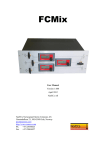
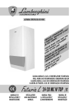
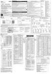
User’s Manual
Cooling design of NP4203MF02
Document No. EA0487EJ1V0UM00 (1st edition)
Date Published November 1999 P
©
Printed in Japan
1999
2
No part of this document may be copied or reproduced in any form or by any means without the prior written
consent of NEC Corporation. NEC Corporation assumes no responsibility for any errors which may appear in
this document.
NEC Corporation does not assume any liability for infringement of patents. Copyrights or other intellectual
property rights of third parties by or arising from use of a device described herein or any other liability arising
from use of such device. No license, either express, implied or otherwise, is granted under any patents,
copyrights or other intellectual property rights of NEC Corporation or others.
While NEC Corporation has been making continuous effort to enhance the reliability of its electronic
components, the possibility of defects cannot be eliminated entirely. To minimize risks of damage or injury to
persons or property arising from a defect in an NEC electronic components, customers must incorporate
sufficient safety measures in its design, such as redundancy, fire-containment, and anti-failure features.
NEC devices are classified into the following three quality grades:
“Standard”, “Special”, and “Specific”. The Specific quality grade applies only to devices developed based on a
customer designated “quality assurance program” for a specific application. The recommended applications of a
device depend on its quality grade, as indicated below. Customers must check the quality grade of each device
before using it in a particular application.
Standard: Computers, office equipment, communications equipment, test and measurement equipment, audio
and visual equipment, home electronic appliances, machine tools, personal electronic equipment and industrial
robots
Special:
Transportation equipment (automobiles, trains, ships, etc.), traffic control systems, anti-disaster
systems, anti-crime systems, safety equipment and medical equipment (not specifically designed for life support)
Specific: Aircrafts, aerospace equipment, submersible repeaters, nuclear reactor control systems, life support
systems or medical equipment for life support, etc.
The quality grade of NEC devices is “Standard” unless otherwise specified in NEC’s Data Sheets or Data Books.
If customers intend to use NEC devices for applications other than those specified for Standard quality grade,
they should contact an NEC sales representative in advance.
Anti-radioactive design is not implemented in this product.
3
4
CONTENTS
1.
Cooling method ............................................................................................................................... 7
2.
Guidelines on allowable maximum temperature of each component in the PDP module ....... 7
3.
Heat radiation design for forced air cooling ................................................................................. 8
4.
Design of air-flow route................................................................................................................... 8
5.
High temperature components.......................................................................................................10
6.
General cautions..............................................................................................................................13
5
6
Generally a color PDP module is assembled in a cabinet together with a power supply, analog video signal
processing circuits and other circuits. The features of the color PDP are a large screen size and slim profile. In
order to take advantage or these features, normally all the above equipment needs to be installed in a compact
cabinet. As a result, the temperature inside the cabinet can become very high. Therefore a color PDP needs an
effective cooling system to radiate the generated heat.
This document describe guidelines for the allowable temperature of components in the NP4203MF02 (42-inch
color PDP module), and an example of a forced-air cooling design.
1. Cooling method
The selection of a cooling method should take into account the operating temperature range and airflow
conditions of the color PDP module. When the module is installed in a narrow space, the ambient temperature
around the module is increased by heat generated by the module and other equipment. In this case, forced air
cooling is essential.
2. Guidelines on allowable maximum temperature of each component in the PDP module
• Resistors (winding, metal oxide film, carbon film)
: less than
90°C (soldering parts of lead-wires)
• Ceramic capacitors
: less than
85°C (surface)
• Electrolytic capacitor (less than 8mm dia.)
: less than
80°C (surface)
• Electrolytic capacitor (more than 8mm dia.)
: less than
85°C (surface)
• Display panel driver IC
: less than
80°C (surface)
• Power transistor, Diode
: less than 100°C (surface)
• MOS FET power module (with aluminum heat sink)
: less than 100°C (surface of heat sink)
• Air-core coil
: less than 100°C (surface)
• Other semiconductors (IC, Photo-coupler, etc.)
: less than
70°C (surface)
In order to obtain better reliability, lower temperatures are recommended wherever possible.
7
3. Heat radiation design for forced air cooling
The required air flow rate and the power of the cooling fan depend strongly on the structure of the cabinet and
heat generated by all the equipment (color PDP module, power supply, analog processing circuits, etc) in the
cabinet.
Therefore, the cooling ability of the fans can not be specified without knowing the cabinet structure and the end
of heat generation of the equipment.
The final cooling design should be fixed only after measuring of the actual temperature of the components in the
PDP module with thermometers.
Cooling fans emit an audible noise. This noise is sometimes regarded as a problem. In order to reduce this
noise, it is recommended to place dampers between the fan and its mountings. It is also effective to use larger
fans running at a lower speed.
Start
Determine temperature
conditions
Air flow route design
Selection of cooling fan
Temperature measurement
Are temperature
conditions satisfied ?
No
Yes
End
Temperature design flow chart
4. Design of air-flow route
It is necessary to create a design where the cooling air can cool all components. The power supply in particular
generates a lot of heat. Therefore it is important to avoid air warmed up by the power supply affecting any other
components in the module.
Figure 1 shows an example of an air flow route design.
8
Figure 1. Example of air flow route design
A
B
Air exhaust
Fan
Power supply
“A” parts cross section
“B” parts cross section
Air exhaust
Air exhaust
Power supply
Air intake
Air intake
9
5. High temperature components
As shown in Figure 1, air normally flow from bottom to top. In this case, the highest temperature components
are shown in figure 2 to 4 for reference. Of course, the temperature of each component varies according to the
cooling air-flow conditions. When the cooling conditions are not uniform, the temperature of other components may
become high.
Therefore, it is recommended to measure the actual temperature of components in the final
assembly.
Figure 2. Common electrode driving module
Surface of top air-core coil
Heat sink surface of PH41
MOS FET power module
PH48
PH41
On board DC/DC
converter
PH49
On board DC/DC
converter
PH48
10
Figure 3. Scan electrode driving module
On board
DC/DC
converter
Heat sink surface of
PH44 MOS FET
driver module.
PH44
PH46
PH45
On board DC/DC
converter
On board DC/DC
converter
On board
DC/DC
converter
Heat sink surface of
PH42 MOS FET
driver module.
PH42
PH47
On board
DC/DC
converter
PH46
PH45
On board
DC/DC
converter
PH44
11
Figure 4. Data electrode driver
Surface of the aluminum-plate
heat sink of data electrode driver.
(left, center and right parts)
Surface of black IC molding
material of scan electrode driver.
Generally, when the air flows from bottom to top, the temperature of the top side data drivers are higher than the
temperature of the bottom side drivers. In this case, it is recommended to measure the temperatures of at least the
top 3 drivers (upper right, upper middle and upper left).
When the temperature is measured with a uniform display pattern like a full white, temperature difference of
each driver is very small because of same driving condition. However, when uses other display pattern like a color
bar, temperature of each driver is different, therefore, when measure the temperature, it is recommended to use a
uniform display pattern like a full white.
12
6. General cautions
6.1 Warnings and Connectors
Warning: Indicates a hazard that can lead to death or injury if the warning is ignored and the product is handled
incorrectly.
Caution : Indicates a hazard that can lead to injury or damage to property if the caution is ignored and the
product is handled incorrectly.
[Warning]
(1) This product uses a high voltage (420 V MAX.). Do not touch the circuitry of this product with your hands when
power is supplied to the product or immediately after turning off the power. Be sure to confirm that the voltage
has dropped to a sufficiently low level.
(2) Do not supply a voltage higher than that specified to this product. This can damage the product and may
cause a fire.
(3) Do not use this product in locations where the humidity is extremely high, where it may be splashed with water,
or where it is surrounded by flammable materials. Do not install or use the product in a location that does not
satisfy the specified environmental conditions. This can damage the product and may cause a fire.
(4) If a foreign substance (such as water, metal, or liquid) gets inside the product, immediately turn off the power.
Continuing to use the product as it is may cause fire or electric shock.
(5) If the product emits smoke, an abnormal smell, or makes an abnormal sound, immediately turn off the power.
If nothing is displayed or if the display goes out during use, immediately turn off the power. Continuing to use
the product as it is may cause fire or electric shock.
(6) Do not disconnect or connect the connector while power to the product is on. It takes some time for the
voltage to drop to a sufficiently low level after the power has been turned off. Confirm that the voltage has
dropped to a safe level before disconnecting or connecting the connector. Otherwise, this may cause fire,
electric shock, or malfunctioning.
(7) Do not pull out or insert the power cable from/to an outlet with wet hands. Doing so may cause electric shock.
(8) Do not damage or modify the power cable. Doing so may cause fire or electric shock.
(9) If the power cable is damaged, or if the connector is loose, do not use the product; otherwise, this can lead to
fire or electric shock.
(10) If the power connector or the connector of the power cable becomes dirty or dusty, wipe it with a dry cloth.
Otherwise, this can lead to fire.
13
[Caution]
(1) Do not place this product in a location that is subject to heavy vibration, or on an unstable surface such as an
inclined surface. The product may fall off or fall over, causing injuries.
(2) When moving the product, be sure to turn off the power and disconnect all the cables. While moving the
product, watch your step. The product may be dropped or fall, leading to injuries or electric shock.
(3) Before disconnecting cables from the product, be sure to turn off the power. Be sure to hold the connector
when disconnecting cables. Pulling a cable with excessive force may cause the core of the cable to be
exposed or break the cable, and this can lead to fire or electric shock.
(4) This product should be moved by two or more persons. If one person attempts to carry this product alone,
he/she may be injured.
(5) This product contains glass. The glass may break, causing injuries, if shock, vibration, heat, or distortion is
applied to the product.
(6) The temperature of the glass surface of the display may rise to 50 °C or more depending on the conditions of
use. If you touch the glass inadvertently, you may be burned.
(7) Do not poke or strike the glass surface of the display with a hard object. The glass may break or be scratched.
If the glass breaks, you may be injured.
(8) If the glass surface of the display breaks or is scratched, do not touch the broken pieces or the scratches with
bare hands. You may be injured.
(10) Do not place an object on the glass surface of the display. The glass may break or be scratched.
14
6.2 Cautions on Design
(1) This product may be damaged if it is subject to excessive stresses (such as excessive voltage, current, or
temperature). The absolute maximum ratings specify the limits of these stresses, and system design must
ensure that none of the absolute maximum ratings are exceeded.
(2) The recommended operating conditions are conditions in which the normal operation of this product is
guaranteed.
All the rated values of the electrical specifications are guaranteed within these conditions.
Always use the product within the range of the recommended operating conditions. Otherwise, the reliability of
the product may be degraded. Use of the product with a combination of parameters, conditions, or logic not
specified in the specifications of this product is not guaranteed. If intending to use the product in such a way,
be sure to consult NEC in advance.
(3) This product emits near infrared rays (800 to 1000 nm) that may cause the remote controllers of other electric
products to malfunction. To avoid this, use an infrared absorption filter and thoroughly evaluate the system
and environment.
(4) This product uses high-voltage switching and a high-speed clock. A system using this product should be
designed so that it does not affect the other systems, and should be thoroughly evaluated.
(5) This product has a glass display surface. Design your system so that excessive shock and load are not
applied to the glass. Exercise care that the vent at the corner of the glass panel is not damaged. If the glass
panel or vent is damaged, the product is inoperable.
(6) There are some exposed components on the rear panel of this product. Touching these components may
cause an electric shock.
(7) This product uses a high voltage. Design your system so that any residual voltage in this product is dissipated
quickly when power is turned off, observing the specifications.
(8) This product uses heat-emitting components. Take the heat emitted by these components into consideration
when designing your system.
If the product is used outside the specified temperature range, it may
malfunction.
(9) This product uses a high voltage and, because of its compact design, components are densely mounted on the
circuit boards. If dust collects on these components, it can cause short-circuiting between the pins of the
components and moisture can cause the insulation between the components to break down, causing the
product to malfunction.
(10) Regulations and standards on safety and electromagnetic interference differ depending on the country.
Design your system in compliance with the regulations and standards of the country for which your system is
intended.
(11) To obtain approval under certain safety standards (such as UL and EN), a filter that passes a shock test must
be fitted over the glass surface of the finished product. In addition, it must be confirmed that the level of UV
emissions is within the range specified by such standards.
(12) If this product is used as a display board to display a static image, image “burn-in” occurs. This means that
the luminance of areas of the display that remain lit for a long time drops compared with the luminance of
areas that are lit for a shorter time, causing uneven luminance across the display. The degree to which this
occurs is in proportion to the luminance at which the display is used. To prevent this phenomenon, therefore,
avoid static images as much as possible and design your system so that it is used at a low luminance, by
setting PLE to the maximum level.
(13) Within the guarantee period, general faults that occur due to defects in components such as ICs will be
rectified by NEC without charge. However, faults due to “burn-in” are not included. Repairs due to the other
faults may be charged for depending on responsibility for the faults.
(14) This product is designed to NEC’s “Standard” quality grade. If you wish to use the product for applications
outside the scope of the “Standard” grade, be sure to consult NEC in advance to assess the technological
feasibility before starting to design your system.
15
6.3 Cautions on Use
(1) Because this product uses a high voltage, connecting or disconnecting the connectors while power is supplied
to the product may cause malfunctioning. Never connect or disconnect the connectors while the power is on.
Immediately after power has been turned off, a residual voltage remains in the product. Be sure to confirm that
the voltage has dropped to a sufficiently low level.
(2) Watching the display for a long time can tire the eyes. Take a break at appropriate intervals.
(3) Do not cover or wrap the product with a cloth or other covering while power is supplied to the product.
(4) Before turning on power to the product, check the wiring of the product and confirm that the supply voltage is
within the rated voltage range. If the wiring is wrong or if a voltage outside the rated range is applied, the
product may malfunction or be damaged.
(5) Do not store this product in a location where temperature and humidity are high. This may cause the product
to malfunction. Because this product uses a discharge phenomenon, it may take time to light (operation may
be delayed) when the product is used after it has been stored for a long time. In this case, it is recommended
to light all cells for about 2 hours (aging).
(6) If the glass surface of the display becomes dirty, wipe it with a soft cloth moistened with a neutral detergent.
Do not use acidic or alkaline liquids, or organic solvents.
(7) This product is made from various materials such as glass, metal, and plastic. When discarding it, be sure to
contact a professional waste disposal operator.
6.4 Repair and Maintenance
Because this product combines the display panel and driver circuits in a single module, it cannot be repaired or
maintained at users’ office or plant. Arrangements for maintenance and repair will be determined later.
6.5 Others
(1) If your system requires the user to observe any particular precautions, in addition to the above warnings and
cautions, include such caution and warning statements in the manual for your system.
(2) If you have any questions concerning design, such as on housing, storage, or operating environment, consult
NEC in advance.
16