1
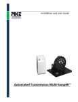
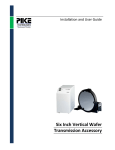
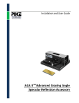
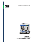
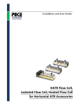
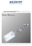
Installation and User Guide
Out-of-Compartment Microplate Reader
The information in this publication is provided for reference only. All
information contained in this publication is believed to be correct and
complete. PIKE Technologies, Inc. shall not be liable for errors contained herein
nor for incidental or consequential damages in connection with the furnishing,
performance, or use of this material. All product specifications, as well as the
information contained in this publication, are subject to change without notice.
This publication may contain or reference information and products protected
by copyrights or patents and does not convey any license under the patent
rights of PIKE Technologies, Inc. nor the rights of others. PIKE Technologies, Inc.
does not assume any liability arising out of any infringements of patents or
other rights of third parties.
This document contains confidential or proprietary information of PIKE
Technologies, Inc. Neither this document nor the information herein is to be
reproduced, distributed, used or disclosed, either in whole or in part, except as
specifically authorized by PIKE Technologies, Inc.
PIKE Technologies, Inc. makes no warranty of any kind with regard to this
material including, but not limited to, the implied warranties of merchantability
and fitness for a particular purpose.
Copyright 1991-2014 by PIKE Technologies, Inc., Madison, WI 53719. Printed in
the United States of America. All world rights reserved. No part of this
publication may be stored in a retrieval system, transmitted, or reproduced in
any way, including but not limited to, photocopy, photograph, magnetic or
other record, without the prior written permission of PIKE Technologies, Inc.
Address Comments to:
PIKE Technologies, Inc.
6125 Cottonwood Drive
Madison, WI 53719
Phone
Fax
E-mail
Web Site
Jan. 1, 2014
(608) 274-2721
(608) 274-0103
[email protected]
www.piketech.com
Contents
Introduction
Specifications
Unpacking Your Accessory
Packing List
Optical Description
Installation
PC and Power Connection
Connecting to your Computer
Powering-Up the Accessory
Accessory Initialization
1
1
2
2
3
4
6
6
6
7
Introduction
The Out-of-Compartment Microplate Reader offers high throughput plate reading capability to UV-Vis
spectrophotometers with standard sample compartments. This allows flexibility to researchers
conducting experiments with traditional accessories such as cuvettes, temperature control and
integrating spheres who may also require microplate reading functionality. Microplate reading capability
is often required in research, drug discovery, bioassay validation, quality control and manufacturing
processes in the pharmaceutical and biotechnological industry and academia. The accessory supports
standard 96-well and 384-well formats. The Microplate Reader can also be adapted to perform
automated measurements of filters, optical components and other materials.
Specifications
Optics
Transfer Optics Module and two UV-Vis/NIR Optical Fiber Cables or,
Transfer Optics Module, one Optical Fiber Cable and Photodiode Detector
Accuracy
+/- 25 μm
Mechanical Specifications
Repeatability +/- 5 μm
Resolution 1 μm
Run Time 96-well plate – 32 seconds
384-well plate – 84 seconds
Computer Interface
USB
Power Requirements
100–240 Volts AC 50/60 Hz
Dimensions (W x D x H)
11.6 x 13.7 x 6"
Weight
15 lbs
The Microplate Reader is controlled by PIKE Technologies’ AutoPROTM 6 software which can be
integrated with most commercial FTIR and NIR software packages.
Launch optics/fiber coupler fitted into the spectrophotometer is required.
PN 350-047100-01
P a g e |1
Unpacking Your Accessory
In order for you to quickly verify receipt of your accessory, we have included a packing list. Please
inspect the package carefully. Contact PIKE Technologies if any discrepancies are noticed.
Packing List
User Manual
AutoPRO6 Manual and Software
Microplate Reader Accessory
PN 350-0047000
PN 350-000071
PN 047-10XXX
Quantity 1
Quantity 1
Quantity 1
UV-Vis Fiber Optical Probe
(1 m), Probe Sold Separately
USB Cable
Cary 60 Detector Cable Access
Plate
PN 047-3030
Quantity 1
Quantity 1
Power Supply
with Power Line Cord
Quantity 1
PN 350-047100-01
P a g e |2
Optical Description
The optical system of the Microplate Reader features a fiber optic probe, and a built-in silicon diode
detector. The light is picked up in the spectrophotometer sample compartment by the Transfer Optics
Module and sent to the plate reader via the optical fiber probe. After passing through the sample, it is
collected by the detector and registered by the spectrophotometer electronics.
Optical Beam Path
Sampling Plate
Figure 1. Optical cutaway view
The mechanical design of the accessory relies on an X, Y stage with both axes driven by high precision
servo motors with optical encoders for speed and reproducibility. USB and DC power are the only
external connections required for this accessory. Programming and control of the Microplate Reader is
done through PIKE Technologies’ AutoPRO6 software, which can be integrated easily with the
spectrophotometer software.
PN 350-047100-01
P a g e |3
Installation
The Microplate Reader module features a small footprint and can be positioned next to or above the
spectrophotometer.
Before performing these steps please ensure that the spectrophotometer power is off.
1. Mount the Transfer Optics Module in the sample compartment of the spectrophotometer. Follow
manufacturer’s instructions to complete this step.
2. Position the Microplate Reader in a desired location and plug the detector cable into the socket
located in the sample compartment of the spectrophotometer as follows:
a. Remove the access plate from the spectrophotometer back wall.
b. Feed the detector cable through the opening and plug it into the socket located on the
side wall of the spectrophotometer sample compartment.
c. Slide the detector cable grommet in the Detector Cable Access Plate slot and re-attach
the plate to the back of the instrument.
PN 350-047100-01
P a g e |4
Detector Cable
Access Plate
Grommet
3. Attach the fiber optic probe to the SMA connector marked “Light Out” on the Transfer Optics
Module.
Figure 2. Completed System
4. Complete the PC and PC connection section on the next page.
5. Slide the probe into the probe holder located on the top of the accessory. Enable the align function
in the spectrophotometer software to monitor the energy. Adjust the probe up and down until the
position of maximum energy is determined. Secure the probe by tightening the two set screws of
the probe holder.
Probe Holder
Set Screws
PN 350-047100-01
P a g e |5
PC and Power Connection
Before performing these steps please ensure that the spectrophotometer power is off.
Power
Terminal
Power
On/Off
USB
Connector
Fuse
Figure 3. Connector panel located on the back panel of the Microplate Reader
Connecting to your Computer
Please load the AutoPRO6 software before connecting the accessory to the PC. Instructions for the
AutoPRO6 software are covered in a separate manual.
Locate the USB port on top of the accessory panel. Connect the USB cable to that port and to a USB port
on your computer.
Powering-Up the Accessory
Plug the DC power line connector to the matching DC power jack on the accessory panel. Connect the
power supply to an AC wall outlet. The green “power on” line LED light will turn on.
Please refer to a separate manual for AutoPRO6 Software installation and use.
PN 350-047100-01
P a g e |6
Accessory Initialization
1. Set up AutoPRO6 software for the correct accessory.
2. Set the accessory to manual mode.
3. Click the Initialize Motors icon (the stage will move slightly and reposition itself at position 0,0).
After this step the Microplate Reader is ready for use and you can set up your experiment as described
in the AutoPRO6 User Manual.
PN 350-047100-01
P a g e |7
6125 Cottonwood Drive · Madison, WI 53719-5120 · (608) 274-2721 (TEL) · (608) 274-0103 (FAX)
[email protected] · www.piketech.com