1
ORGANIC VAPOR METER (OVM) I DATALOGGER
INSTRUCTION MANUAL
PIN 16860
THIS EQUIPMENT IS SUITABLE FOR USE IN
CLASS I, DIVISION 2, GROUPS (AS APPLICABLE)
OR NON-HAZARDOUS LOCATIONS ONLY.
WARNING - EXPLOSION HAZARD - SUBSTITUTION
OF COMPONENTS MAY IMPAIR SUITABILITY FOR
CLASS I, DIVISION 2.
THERMO ENVIRONMENTAL INSTRUMENTS INC
8 WEST FORGE PARKWAY
FRANKLIN, MASSACHUSETTS
02038
TELEPHONE: (508) 520-0430
FACSIMilE: (508) 520-1460
1-9-96
INSTRUMENT
WARRANTY
WARRANTY. Subject
to the exceptions
stated
below,
Thermo Environmental
Instruments
Inc. agrees to correct,
either
by repair
or
at our opinion,
by replacement,
any defects
in materials
or workmanship which develop
within
one year from the date of surface
shipment,
parts
and labor
supplied
free-of
charge
and surface
transportation
costs to ~ borne by the offeror
both ways, provided
that
the investigation
and inspection
defects
developed
under
normal and proper use.
The exceptions
mentioned above are: (1) All items claimed must be
returned
to Thermo Environmental
Instruments
Inc.,
transportation
charges collect,
and will
be shipped prepaid
and charged to the
customer unless the item is found to be defective
and covered by
the warranty
in which case Thermo Environmental
Instruments
Inc.
will
pay
all
surface
transportation
charges;
(2)
Thermo
Environmental
Instruments
Inc.
agrees to extend to the customer
whatever warranty
is given to Thermo Environmental
Instruments
Inc.
and incorporated
into products
sold to the customer;
(3) Thermo
.Environmenta I Instruments
Inc. shall
be released
from all obligations under this warranty
in the event repairs
or modifications
are
made by persons other than its own authorized
service
personnel,
or
service
personnel
from an authorized
representative,
unless
such
repair
is
minor,
merely
the
installation
of
a new plug-in
component;
(4) If any model or sample was shown to the Purchaser,
such model or sample was shown merely to illustrate
the article
and
not to represent
that any article
delivered
hereunder would conform
to the model or sample;
and (5) Spare parts
are warranted
for
ninety
(90) days.
THE FOREGOING WARRANTY IS EXCLUSIVE AND IN LIEU OF ALL OTHER
WARRANTIES, WHETHERWRITTEN, ORAL, IMPLIED OR STATUTORY. SELLER
DOES NOT WARRANT MERCHANTABILITY OR FITNESS FOR ANY PARTICULAR
PURPOSE, OR MAKE ANY OTHER WARRANTYOR AGREEMENT EXPRESSED OR
IMPLIED WITH RESPECT TO ANY ARTICLES COVEREDHEREUNDER. tHERE ARE
NO WARRANTIES WHICH EXTEND BEYOND THOSE EXPRESSLY STATED IN THIS
CONTRACT.
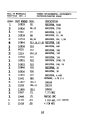
580B USER MANUAL
TABLE OF CONTENTS
Page
Section
1
Xntroduction
1.1
About this manual
1.2
Instrument
OVerview
1.3
580B Features
1.0;1
1~1
c
1-3
Principle
of Operation
2.1
Photoionization
Detector
Strategy
2.2
Program Operation
2.3
Main Menu
2.4
Parameters Mode
2.5
Access Mode
2.6
Clock Mode
2.7
Communication Mode
2.8
Battery/Charger
2
3
Service I Hardware
3 . 1 Lamp Insertion
3.2
3.3
"
5
2.-4
,,2-7
"2--8
2-13
"2-15
~-i5
~-17
3-1
3-4
3-4
and Removal
Calibration
Charge
Calibration
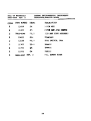
4.1
General
4.2
4.3
Factory
Methods
4.4
4.5
of Various Materials
in Air
580B Calibration
Determination
of Response Factors
Calibration
Test of Model
of Gene~ating
Concentrations
580B
Applications
5.1
General
5.2
Vinyl Chloride
Monomer
5.3
Monitoring
Isolated
Plant Areas for
Toluene and Methyl Isobutyl
Ketone
5.4
Petroleum Ether Vapor in Workspace Air
5.5
Leak sourcing
5.6
Afterburner
Efficiency
5.7
6
2...1
Operation
Sample Collection
Co11ection
6.1
6.2
6.3
of Unknown Environments
TechDiqa..
General
Bag Sample Collection
Collection
Using Charcoal
Tubes
4-1
4-1
4-1
4-7
4-8
5-1
5-1
5-2
5-4
5-5
5-5
5-6
6-1
6-2
6-3
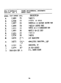
7
C~'!D.icatioD.
7.1
7.2
7.3
8
A
Printer
Computer
Communication
Plow Chart
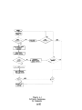
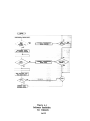
8.1
Quick Start-up
8 . 2 Detai led Flow
Software
7-1
7-1
7-1
Chart
8-1
8-1
A.l
cation
Introduction
A.2
A.3
Printer
Mode Interface
Computer
Mode Interface
C~~n"
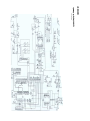
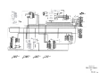
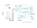
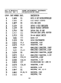
B
Schematics
c
580B
D
Material
E
580B
F
Cammon Organic
G
Variable
Block
Diagram
List
Detailed
G.l
G.2
G.3
A-l
A-l
A-2
and
Silkscreen
Drawing
Solvents
Dilut;ion
Probe
and Gases Data Sheet
As.~ly
General
Technical Consideration
Calibration
of the Dilution
B
Probe
Extension
:I
Water
Trap
J
Revised
K
RS-232
Documents
Xnformation
Sheet
Drawing'
Probe
G-l
G-l
G-l
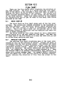
SECTIONI
INTRODUCTION
1
INTRODUCTION
The 580B is a portable
Organic
Vapor
Meter
(DVM),
which
detects
and quantitates
most organic
vapors
with
a highly
sensitive
photoionization
detector
(PIC).
The 580B has an operating
range of 0-2000
parts
per million
(ppm) with
a minimum detectable
of 0.1 ppm.
No support
gases are required.
The 580B is
controlled
by a microprocessor
which
provides
many features
that
were not previously
available.
Maximum siqnal
hold,
detector
linearization,
overrange
lockout,
IBM PC (or
compatible)
interface,
extensive
data
logging
capabilities
and
much more.
With
the many features
provided
by the
580B leak
detection,
head space
measurements,
and field
survey
are
all
easily
accomplished.
Completely
portable,
the 580B operates
from
internal
batteries
for eight
hours
in the field.
1.1 ABOUTTHIS MANUAL
This manual is broken down into eight
chapters.
The first
chapter
(this
one) provides
a general
overview
of the 580B.
Chapter two discusses,
in great detail,
the extensive
facilities
of the 580B.
The focus of this
chapter
is on how to use the
seven switches
to access the various
facilities.
Chapter three
explains,
in detail,
how to perform
routine
maintenance
on the
580B.
Chapter four is a technical
discussion
of calibration
and
methods for generating
standards.
Chapter
five
is a technical
discussion
of a few applications
which illustrate
some of the
uses of the 580B.
Chapter
six
is a technical
discussion
of
methods for collecting
a sample using the 580B.
Chapter seven is
a discussion
of the communication
facilities
provided
by the
580B.
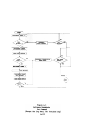
Chapter
eight
contains
two flow charts
which illustrate
the 580B software
flow.
This chapter
is a helpful
tool
for the
new user.
Appendix
A is a detailed
explanation
of the 580B
communication
protocol.
This chapter
is provided
in order
to
allow a programmer to develop specialized
communication
software
for the 580B.
There are several
other
addendums which contain
miscellaneous
information
about the 580B.
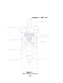
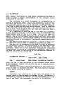
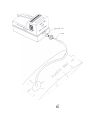
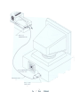
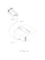
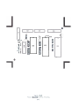
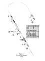
1.2
INSTRUMENTOVERVIEW
58GB.
This section
describes
Each number refers
to
various
points
of interest
a number in Figure 1.1.
on the
1.
POWERPLUG - The power plug is used to run the instrument from its
internal
batteries.
There is a chain attached
to
the power plug so that it will
not be lost.
2.
RS-232
CONNECTOR- This
1-1
connector
is
used for
communi-
cation
with
a serial
printer
provided
with
the instrument
or
fits
computer.
into
the
A communication
receptacle.
cable
3.
KEY PAD - There are seven switches
which operate
the
580B.
The switch marked ON/OFF is used to turn the pump and lamp
on and off.
The switch
marked LIGHT will
turn on backlighting
for the two line
display.
The other five
switches
perform
various functions.
For a detailed
description
of the function
of
each switch see chapter two or the flow charts
in chapter
eight.
DISPLAY-
4.
The 580B has a two line
by sixteen
character
display.
5.
for
SHOULDER STRAP carrying
the
5808.
6.
There
SAMPLE EXIT PORT
detector
through
is
-
The
displacement
by a positive
the exit
port.
an adjustable
shoulder
580B sample is drawn
pump and then
sent
strap
into
the
back
out
NOTE : The photoionization
detector
is a non destructive
detector
so the sample may be collected
at the exit
for further
analysis
(see Chapter Six).
-
The
580B pump draws the
7.
PUMP
8.
MOUNTINGSCREWS There
sample into
the detec-
tor.
-
hold the 580B top and bottom
designed so that they do not
of the case top.
the
are four
together.
fallout
9.
DETECTOR - The photoionization
lamp and high voltage
power supply.
10.
SAMPLE INLET
through the sample inlet
- Sample is
at the front
captive
detector
drawn
of the
12
BASE BARHESS - The base harness
on the case top.
1.3
is
shown with
into
the
580B.
11.
SIGBAL CABLE - The PID signal
is
microprocessor,
for analysis,
via the coaxial
.
screws which
The screws are specially
when they are loosened out
detector
brought
signal
pI u9s into
up to
the
cable.
a connector
580B FEATURES
This
section
provides
features
of the 580B.
After
have a good idea of what the
three
will
explain,
in detail,
a brief
overview
of the
various
reading
this
section
the user should
instrument
can do.
Chapters
two and
how each feature
is selected.
TORIfDlG ON PUMP AIm LAMP
by pressing
the ON/OFF switch
be on).
CALIBRATION
Calibration
-
-
The pump and lamp are turned
(the
of
1-3
instrument
the
580B
power
is
must
extremely
on
already
impor-
tanto
Chapter
two explains
how to calibrate
the 580B in great
detail.
Chapter
four
discusses
at length
some of the basic
theory
and aethods behind calibration.
It is strongly
suggested
that this chapter
be read in order to gain a deeper understanding
of usage of the 580B.
Chapter three also discusses
calibration.
- Once the
COB~TIOBS
lamp and pump have been turned
on
the 580B begins
to display
the concentration
of the incoming
sample on the bottom line of the display.
Normally
the top line
of the display
will
be a bar graph (logarithmic
on a scale
of
zero to 2000).
The operator
may however select
the MAX HOLD mode
of operation.
When in MAX HOLD, the top line of the display
will
show the highest
concentration
recorded.
LOGGIMG - The 580B provides
extensive
facilities
for logging
information.
The operator
may save a particular
reading
along
with a six digit
location
code and a date and time sta.p.
If the
580B is in the MAX HOLD .ode when logging
is initiated
then the
max hold value will
be logged.
AUTO LOGGXRG -
Logging
may be perforaed
automatically
by
using
the 580B's
auto logging
feature.
Auto logging
is not
allowed while in the MAX HOLD mode. When auto logging
is selected a LOGGING INTERVAL is selected
(anywhere from one second to 99
minutes and 59 seconds).
At the end of each logging
interval
the
present
concentration
will
be logged (the location
code is automatically
incremented
each time).
-
AVERAGE
The 580B normally updates the concentration
once
per second.
The operator
has the option
of setting
the averaging
time anywhere from one second up to four .inutes.
NOTE : The botto.
line of the display
until
the first
averaging
interval
is co.pleted.
will however be updated each second.
will
be blank
The top line
factor
may be used in order to
relate
a particular
gas to the calibration
gas.
When computing
the displayed
concentration
the microprocessor
multiplies
the
measured concentration
by the response
factor
and displays
the
result.
If the response factor
is one, then the concentration
is
not changed.
Chapters
four and five
explain
some uses of the
response factor.
RESPONSE PAL~vR
- A response
saved
LAMP SELECTION - The 5808 allows
for
for
one 10.0
eV lamp and one 11.8
lamps
tion.
to be switched
A lamp serial
calibration
eV lamp.
in the field
without
requiring
number may also be entered.
data to be
This
allows
recalibra-
ALARM - An alarm level
may be selected.
The 5808 will
sound
an audible
alarm
(the top line
will
also
indicate
an alarm)
whenever the concentration
goes above the selected
alarm level.
ACCESS
ious
features
-
The
580B provides
may be "locked
four
out."
1-4
access levels
User
identification
so that
varnumber
and instrument
number are also
CLOCK - The
when the instrument
provided.
5808 has an internal
power is cut off.
clock
which
will
run
even
COMMUNICATION - The 580B has a serial
communication
port for
outputing
data to a serial
printer.
Many of the 580B features
may be accessed from a remote computer through
the serial
communication
port
(there
is communication
software
available
which
will
run on an IBM PC or clone).
DISPLAY
the
580B's
LOGGED DATA -
two line
The logged data may be displayed
display.
1-5
on
SECTIONII
PRINCIPAL
OF OPERATION
PHOTOIONIZATIONDETECTOROPERATION& THEORY
1 GENERAL
The sample is drawn into
the ion chamber by a pump down
stream of the detector.
Here the sample is bombarded by ultraviolet
light
(uv) exciti~g
the molecule.
If the energy,
(hU) of
the UV light
is greater
than the ionization
potential
(IP) of the
sample molecule
(R) an electron
will
be removed,
ionizing
the
molecule.
A positively
charged molecule
and a free electron
are
produced,
as
:
R + hu ->
Several
typical
reactions
follow:
R+ + e'
-
C6B6 (benzene)
+ bu ->
C6B6+ + e
.H2C=CHCl
+ hu
H2C=CHCl + + e'
(VCM)
C3HS (propane)
->
+ hu ->
C3Hs+ + e
-
IP = 9.2
eV
IP
-
9.9
eV
IP
=
10.9
eV
For this
reason
the ionization
potential
of the subject
molecule
plays
an important
role in selecting
the lamp energy.
Ionization
potentials
are expressed
in electron
volts
(eV).
A
list
of ionization
potentials
can be found in Appendix E of this
manual or a more complete list
in the CRC "Handbook of Chemistry
and Physics".
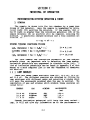
2.1.2 LAMP ENERGIES
There are
and 11.8 eVe
lamp envelopes
will
pass the
combination
of
listed
below:
ENERGY
10.0
10.6
11.8
lamp,
eV
eV
eV
three lamps available
from TEI, 10.0 eV, 10.6 eV,
The different
energies
are obtained
by filling
the
with different
gases and selecting
a window which
wavelenqth
produced when the gas is excited.
The
gas and windows which produce these energies
are
GAS
Krypton
Krypton
Argon
Though ionization
it will
not give
WINDOW
MgF
MgF
LiF
potential
will
any information
2-1
WAVELENGTH
(nm)
123.6
117.4
105.1
help the
as to the
user select
performance
a
of
the detector
in measuring
a specific
compound.
The response
of
the system varies
considerably
from compound to compound even
though they may have the same ionization
potential.
Some generalizations
may help the user obtain
a feeling
for the difference
in response between compounds.
2.1.3
COMPARATIVE
RESPONSE
The following
made to quantitate
Decreasing
is an idealized
the relationship,
PID Response:
response chart.
No attempt
it's
a guideline.
is
Aromatic
Compounds
Unsaturated
Compounds
Saturated
Compounds
Ketones
Alcohols
Compounds with Sub Groups
It becoaes obvious
that
sensitivity
is influenced
by the
electronegativity
of the molecule
though this
is not a predictable .easure
of perfor.ance.
The only true test of performance
is
to measure the specific
compound of interest
and compare it to a
good performing
standard
such as isobutylene.
2.1.4
RESPONSEFACTORS
This relative
comparison
with isobutylene
mentioned
above is
a very effective
way of measuring
a variety
of compounds without
the need to recalibrate
for each compound.
The development
of a RESPONSE FACTOR allows
the operator
to
correct
the instrument's
response given a one to one correspondence for all compounds measured,
using isobutylene
as the reference standard.
Hote:
Because there
is variation
in lamp production
and hence
performance,
it is suggested
that
all
calibration
and subsequent
development
of response factors
be done on the same lamp/instrument combination.
The preparation
of standards
and the development
of response
factors
is discussed
in subsequent
sections
of this
manual.
Once
the response factor
is generated,
it is entered
into the 580. The
instrument
automatically
reports
the concentration
of the compound measured in relative
units.
It is important
to recognize
that
all
compounds measured at that time will
be reported
relative
to the response
factor
entered
in the instrument.
For
example,
if we have calibrated
the instrument
on isobutylene
and
have entered
a response factor
for benzene, we will
read concentrations
with a one to one correspondence
to benzene.
If during
these measurements toluene
or any other compound is encountered,
the instrument
will
report
the concentration
as if it was measuring benzene.
For this
reason
care should
be taken when using
this
facility.
of
The above
discussion
PID perforaance.
To
should
further
give
the
understand
2-2
reader
a good
the
intricacies
overview
of the
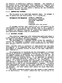
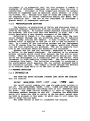
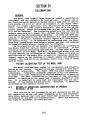
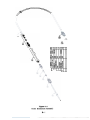
~~~~-:&."tf:'?;
Photo
Figure
2.1
Ionization
2-3
Detector
SAMPLE INLET
instrument
it
is suggested
that
the user prepare
a number of
standards
of different
compounds and measure them relative
to
isobutylene.
Included
in this
comparison
should
be several
mixtures
of compounds such as gasoline,
paint
thinner,
or cleaning sol vent,
etc.
Through this
type of study the inequity
of the
PID response
will
be better
understood
making the Model 580 a
more effective
tool.
The use of the instrument
is discussed
in
greater
detail
in subsequent
sections.
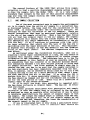
2.1.5
PHOTOIONIZATIONDETECTOR
The detector
is constructed
of Teflon and stainless
steel
to
eliminate
chemical
interaction
with the surfaces
that are encountered by the sample.
To further
reduce possible
interaction
with
the surfaces,
the flow rate thru the detector
is high,
400 - 500
cc/min developing
a very dynamic transport
of the sample.
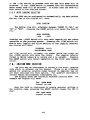
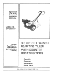
Referring
to Fiqure
2.1, the sample is drawn into
the ionization
chamber through
the jet
electrode
where the UV radiation
from the lamp ionizes
the sample.
A bias voltage
of several
hundred volts
is applied
to the jet to aid in the collection
of
ions.
As a result
of the ionization
process and the impingement
of the UV energy from the lamp on the saaple,
positively
charged
ions and free electrons
are produced.
The jet is negative
relative to the collector
where the electrons
are collected.
Between the jet and the collector,
separated
on both sides
by Teflon,
is the guard electrode.
Its function
is to eliminate
surface
currents
which could
flow between the two active
.,electrades.
When the Teflon
surfaces
become dirty
during
use, there
can be the development
of a conduction
path on the Teflon,
which
increases
in high
humidity
situations.
The guard
electrode
eliminates
this
path.
The collector
electrode
is connected
to
the electrometer
which measures the ion current
produced
during
the ionization
process.
The sample is moved through
the detector
by an external
pump which is on the exit of the detector.
2.2 PROGRAMOPERATION
Z.Z.l
INTRODUCTION
The 5808 has seven
They are labeled:
ON/OFF
switches
located
just
MODE/STORE RESET LIGHT
+/INC
below
the
-/CRSR
display.
SPKR
The ON/OFF switch toggles
the lamp and puap power between on
and off.
The MODE/STORE,RESET, +/INC, -/CRSR and SPKR switches
all have various
meanings (including
none at all)
depending
upon
the mode.
The SPKR switch
normally
is used to toggle
the
instrument
speaker between on and off.
Pressing
the MODE/STORE
switch will
cause the 5808 to return
to the Run mode, except when
the 5808 is already
in this mode. In which case it will
cause the
580B to enter the Log mode.
The LIGHT switch
is used to illuminate
the display.
2-4
The 580B has
modes.
The modes
several
modes.
Some of the modes may have
and sub modes are tabulated
below.
Run mode
Concentration
meter
Max hold
Log mode
Parameter mode
Calibration
mode
Access mode
Clock mode
Communication mode
sub
normal
The following
sections
will
describe
each mode and how to
get to them and through them.
It is strongly
suggested that this
section
be carefully
read and that the 580B be used along with
the manual in order to re-enforce
the manual.
2.2.2
POWERFOR LAMP AND PUMP
When the 580B is first
turned
on (see section
1.3)
the
display
will
indicate
that
the lamp is not lit.
Pressing
the
ON/OFF switch
will
tell
the microprocessor
to turn on the lamp
and the pump. The microprocessor
will
send power to the lamp and
pump and then "look"
to see if the lamp is actually
lit.
If it
did not light
then the microprocessor
will
try again.
If after
fourteen
then the microprocessor
seconds the
will indicate
lamp still
will
not
a lamp out condition.
light,
In the event that the microprocessor
is unable to light
the
lamp, check the seating
of the lamp (see section
3.1).
If the
problem persists,
call
service.
Once the lamp is lit,
the display
will
show the PPM (parts
per million)
on the bottom line.
The top line will
either
be a
bar graph or the maximum reading
(see section
2.2.3).
To turn
switch.
2.2.3
the
lamp and pump off
simply
press
the
ON/OFF
RUN MODES
The 580B has two run modes, Max Hold and Concentration
meter.
The run mode is selected
in the Parameters
section
(see
section
2.4).
In the concentration
meter mode the top line
of
the display
will
be a bar graph.
The bar graph is a logarithmic
bar graph over the range of 0 to 2000 PPM. The bar graph is
intended
as a rough visual
indication
of the current
PPM. The
bottom line will
indicate
the exact PPM.
In the Max Hold mode the top line
of the display
will
indicate
the maximum reading.
The bottom line
of the display
will
indicate
the current
PPM. Whenever a new maximum is seen,
the top line will
be updated.
The Max Hold reading may be reset
by pressing
the RESET switch while in the run mode.
2.2.4 LOG MODE
The ability
to
"log"
data
2-5
is
one of the
580B's
greatest
features.
Readings
may be stored
for
later
analysis.
Each
reading
will
have a date and time as well
as a location
code
associated
with
it.
Up to over 700 readings
may be stored.
Logged data may even be sent to a printer
or computer via an RS232 serial
communication
port
(see section
2.7).
The Log mode is entered
from the Run mode by pressing
the
MODE/STOREswitch.
When this
switch
is pressed from the Run mode
the display
will
show:
LOG THIS
VALUE?
on the top
line
and either
PPM or
depending
upon which
run mode the
pressing
the +/INC switch
the display
LOC.
on the top
The location
switch
the
pressing
the
digit.
The
time a data
MAX PPM on the
bottom
580B is currently
in.
will
then show:
line
By
CODE 000001
line
(the
actual
location
code may not
be 000001).
code may now be entered.
By pressing
the
+/INC
number
above
the
cursor
may be incremented.
By
-/CRSR switch
the cursor
may be moved to the next
580B aut08atically
increments
the location
code each
point
is logged.
Once the
desired
location
code has been entered,
pressing
the MODE/STORE switch
will
"log"
the data point.
This
means that
the reading
displayed
on the bottom
line,
along with
the location
code,
the current
date and the current
time will
be stored
into
the 580B's memory. The 580B will then return to the Run mode.
If for any reason
logging
is not desired,
pressing
the RESET
switch
rather
than the MODE/STORE switch
will
cause the value
not
to be stored.
The 580B will
then go back to displaying:
LOG THIS
Pressing
mode.
the
mode switch
will
VALUE?
now return
the
5808 to
the
Run
It is possible,
when attempting
to log a data point,
that
rather
than the display
showing "LOC. CODE 000001" it will
show
"BAR CODE:
."
Don't be alarmed.
This has happened becouse
the location
mode selection
is not properly
set.
Section
2.4.3
describes
how to set this
parameter.
Pressing
the mode/store
switch
will
cancel
the logging
operation
and return
to the run
mode. The location
mode selection
should be changed as described
in section
2.4.3.
2.2.4A AUTO LOGGINGMODE
The 580B may be instructed
to
automatically
109 data
accordin9
to a predefined
time interval.
AUTO LOGGING is selected from within
the Parameters
section
(see section
2.4).
At the
end of the 1099in9
interval
(settable
from 1 second up to 99
minutes
and 59 seconds)
the current
average ppm value
will
be
logged and the loq9in9
interval
will
be restarted.
NOTE: Auto
2.2.5
logging
is
not
allowed
with
the
Max Hold mode.
SPEAKER
While the 580B is in the Run mode the speaker may be turned
on.
The speaker will
generate
a "clicking"
which will
increase
in speed as the concentration
increases.
The purpose
of the
speaker is to give the operator
an audible
indication
of the PPM.
The speaker may be turned on or off by pressing
the SPKR switch.
The speaker
rate
may also be changed by changing
the switches
located
inside
of the instrument.
only one of the four speaker
rate switches
should be on (in the down position)
at any time.
2.2.6
LOWBATTERY
The 580B will
The warning
bottom
line
580B should
display
a warning
when the battery
is
low.
will
be a flashing
B in the
left
hand
corner
of the
of the
display
when the
580B is in the
Run mode.
The
be recharged
when the
low battery
warning
is activat-
ed.
2.2.7
OVERRANGE
warning
if the
The 580B will
display
an overrange
The
top
line
of
the
display
concentration
goes above 2000 PPM.
will
show:
OVERRANGE
Once an overrange
condition
occurs the instrument
will
"lock
out".
This means that the overrange
warning will
continue
to be
displayed
until
the instrument
is brought
to a "clean"
area.
A
clean area is defined
to be an area where the concentration
of
organic
vapors is below 20 PPM. The 580B will
continue
to indicate PPM on the bottom line during
an overrange
condition.
2.2.8
ALARM
The 580B has an alarm which will
sound if the PPM rises
above the alarm setting.
The alarm setting
is entered
in the
Parameters
mode (see section
2.4.3).
If the speaker
is not
activated
then the alarm will
of course not be heard.
Once the
PPM drops below the alarm setting
the alarm will
turn off.
The
top line
of the display
will
also
indicate
when there
is an
alarm condition.
MAIN MENU
By
pressing
pressing
the MODE/STORE
the
-/CRSR
switch
when
580B will
display
the
switch
asked
main menu:
R/COMM
+/ACCESS
/PARAM
S/CLOCK
-
2:"r
if
from
the
logging
Run
is
mode and
desired,
then
The other
four
operating
modes (Communication,
Parameters,
Access and Clock) may be entered
from the Main menu.
The operating mode may always be returned
to by pressing
the MODE/STORE
switch.
2.4 PARAMETERS
MODE
All
of the 5808 operating
Parameters
mode.
The 5808 is
Parameters mode.
parameters
are
also calibrated
entered
in
from within
the
the
The Parameters mode may be entered by pressing
the -/CRSR
switch from the main menu.
There are nine different
sections in the Parameters mode.
1.
2.
3.
4.
5.
6.
7.
8.
9.
Run mode selection
Auto logging
selection
Location
mode selection
Average
time selection
Alarm setting
Lamp selection
Response
factor
setting
Calibration
Free space indication
Pressing
the +/INC switch
will
advance the 5808 to the next
section.
pressing
the -/CRSR will
advance the 5808 to the previous section.
Each section
and any of its
sub-sections
will
be
described
in the following
pages.
It is important
to note that
when the 5808 is in a sub-section
of any of the above sections
that the +/INC and -/CRSR switches
will
have a different
.eaning.
This may seem confusing
at first
but will
become clear
after
stepping
through
each section.
2.4.1
Hold
RUN MODESELECTION
There are two Run modes.
concentration
(see Section
2.2.3).
The top line
of
CONC.
the botto.
line
will
botto.
line
~1'~
show:
"RESET"
the
aeter
normal
and Max
the display
will
show:
will
TO CHG
alternate
every two seconds with:
MAX HOLD
if the 5808 is in the Max Hold
will
cause the 5808 to show:
+
.ode.
MAX HOLD
= USE/ - = NO
2-8
Pressing
the
RESET switch
if the +/INC switch
is pressed
then the Max Hold mode will
be
selected.
If the -/CRSR switch
is pressed then the Concentration
meter normal mode will
be selected.
In either
case the 5808 will
then return
to the previous
screen.
2.4.2 AUTO LOGGINGSELECTION
The 580B can be confiqured
The top
line
of the
display
to automatically
will
log data points.
show:
AUTO LOGGING
"ON"
The bottom
or "OFF".
line
will
alternate
between "RESET TO CHG." and
Pressing
the RESET switch will
cause the 580B to
show:
AUTO LOGGING
+/ON
-/OFF
Pressing
the -/CRSR switch will
turn auto logging
off and return
operation
to the previous
screen.
Pressing
the +/INC switch will
enable auto logging
and allow
setting
of the logging
interval.
The display
will
show:
INTERVAL
"RESET"WHEN
00:01
DONE
The +/INC switch will
increment
the number above the cursor
and
the -/CRSR switch
will
move the cursor.
The logging
interval
format
is MM:SS (where M is minute and S is second).
Pressing
the RESET switch will
return
operation
to the first
auto logging
screen.
2.4.3
LOCATION MODE SELECTION
The 580B may be configured
to accept
a six digit
location
code which is entered
via the keypad.
There is an alternate
method for entering
location
codes however UL approval
has not
yet been obtained
for this
option.
For updated
information
contact
Thermo Environmental
Instruments
inc.
The display
shows the currently
selected
location
mode.
For
example the display
will
show:
Loc.
n reset
code mode
II
to
chg.
When the 580B is configured
to enable operator
the location
code, pressing
the RESET switch
causes
show:
Bar code mode
"reset"
to chg.
2-9
editing
of
the 580 to
The 580B is now configured
for the alternate
(which
is not
presently
available
for
use
locations).
Pressing
the reset
switch
will
cause
configured
for location
code mode.
location
mode
in hazardous
the 580B to be
2.4.4 AVERAGETIME SELECTION
The 5808 can be confiqured
once a second up to once every
show:
Pressing
the
to display
the
four minutes.
AVERAGE
=
"RESET"
TO CHG
RESET switch
will
average PPM from
The display
will
0: 01
cause the
5808 to
show:
AVERAGE = 0:01
"RESET"WHEN DONE
The +/INC
switch
will
increment
the -/CRSR switch
will
move the
is M:SS (where M is .inutes
and
HOTE: The maximum averaqinq
the number above the cursor
and
cursor.
The average
time
format
S is seconds).
interval
is
four
minutes.
2.4.5 ALARMSETTING
The 580B will
display
the current
alarm settinq
on the top
line
of
the
display.
The
setting
may be changed
by
simultaneously
pressing
the RESET switch
with
either
the +/INC
switch
to increment
the digit
above the cursor
or the -/CRSR
switch to move the cursor.
2.4.6
LAMP SELECTION
The
580B will
display:
LAMP
on the top line.
onds between:
The bottom
line
"RESET"
and the
number.
i.e.
currently
selected
the
RESET switch,
the
+/lOeV
2-10
alternate
every
two
sec-
TO CHG
lamp setting
11.8eV
By pressing
will
and its
associated
000000
5808 will
-/lleV
display:
serial
on the bottom line.
pressing
the +/INC switch
will
select
the
10.0 eV lamp.
Pressing
the -/CRSR switch will
select
the 11.8eV
lamp.
In either
case the 580B will
then allow
editing
of the
lamp serial
number.
The display
will
show:
SERIAL #
000000
"RESET"WHEN DONE
The +/INC
switch
will
increment
the number
the
-/CRSR
switch
will
move the cursor.
switch
will
return
operation
to the original
above the cursor
and
Pressing
the
RESET
lamp screen.
When using a 10.0 eV lamp or a 10.6 eV setting
should
ed.
When using
an 11.8 eV lamp the 11 eV setting
selected.
2.4.7
be selectshould
be
RESPONSEFACTORSETTING
The current
Response Factor
setting
will
be displayed
on the
top line
of the display.
The Response
Factor
may be changed
by
simultaneously
pressing
the RESET switch
with
either
the +/INC
switch
to increment
the digit
above
the
cursor
or the
-/CRSR
switch
to move the cursor.
The response
factor
is
used to
equate
the
response
of
one
organic
vapor
with
that
of the calibration
gas.
The current
reading
is always
multiplied
by the response
factor
in order
to
obtain
the displayed
concentration.
A response
factor
of one
will
not change the displayed
concentration.
2.4.8
CALIBRATION
The 580B will
display:
TO
CALIBRATE
"RESET"
"
The
,-
calibration
mode
may
be
entered
by
pressing
the
RESET
SWl.'t:.cn.
The
580B.will
display:
RESTORE BACKUP
+ = YES
The previous
calibration
information
may be restored
by
pressing
the +/INC switch.
The 580B will
then return
to the
previous
screen.
If the backup is not desired,
by pressing
the
-/INC switch
the calibration
routine
will
continue.
The display
will
show:
ZERO GAS
RESET WHEN READY
2-11
Once zero gas has been introduced
pressed.
The 580B will then zero the
display:
the RESET switch
instrument.
should
be
The 580B will
MODEL 580B
ZEROING
Once the
5808 has been zeroed
SPAN PPM
ously
The Span
pressing
the
=
5808 will
display:
0000
gas concentration
the RESET switch
may now be entered
by simultaneand either
the +/INC
switch
to
cursor or the - /CRSR switch
to move
increment
the digit
above the
the cursor.
Once the span gas concentration
+/INC switch should be pressed.
The 5808 will
then display:
has been entered
the
SPAN GAS
RESET WHEN READY
Once the span gas has been introduced
the RESET switch
should be pressed.
The 580B will
then calibrate
the instrument.
The 580B will
display:
MODEL 5808
CALIBRATING
the
Once the 5808 has been calibrated
beginning
and display:
the
5808 will
go back
to
"RESET" TO
CALIBRATE
If
reading
during
the zeroing
or calibrating
of the
was not seen then the 5808 will
display:
580B a steady
CAL ERROR
RESET WHEN READY
Pressing
the RESET switch will
return
calibrating
(depending
of course on which
See section
4.1 for
tips
on calibrating
it
the 580B to zeroing
came from).
the
or
5808.
2.4.9 FREE SPACEINDICATION
This section
will
give a rough indication
of how much room
is left
for logging
data points.
The screen will
display
a bar
graph on the top line and the amount of free space on the bottom
line.
The nuaber indicates
the total
number of bytes which are
available.
Each data point takes fifteen
bytes.
Other bytes may
also be needed in order
to store
other
important
information.
This is why only a rough indication
of room may be given.
2-12
2.5
ACCESSMODE
The Access mode is entered by pressing
the +jINC switch
from
the main menu.
The 580B has four
access levels,
zero through
three.
Level
zero will
only
allow
the operator
to log data
points
and of course to change access levels
(only if the access
code is known).
Level one will
also allow the user to change the
user identification
number.
Level
two will
allow
the user
complete access to the Parameters
mode, and allow viewing
of the
date and time.
Access level
three allows complete access.
The access mode has three sections:
1.
2.
3.
Pressing
section.
previous
Access level
User identification
Instrument
number
number
the +/INC switch
will
advance
Pressing
the -/CRSR switch will
section.
the 580B to the next
advance the 580B to the
TABLE OF ACCESS LEVELS
OPERATIONS ALLOWED
ACCESS LEVEL
0
Change access
Log data
1
All above operations
view time and date
View communication
format
Display
logged data
Change user I.D.
2
All above operations
Change operating
Parameters
Reset logged data
3
All
2.5.1
operations
level
available
ACCESSLEVEL
The screen
will
display:
3
ACCESS LEVEL
"RESET" TO CHG
By pressing
the
RESET switch
the
580B will
KEY
00003
"RESET" WHENDONE
2-13
display:
Please note that in both screens the 3 indicates
the current
access level
and may not necessarily
be a three.
In order to change the access level
the +/INC switch
may be
pressed
to increment
the digit
above the cursor
and the -/CRSR
switch
may be pressed
to move the cursor.
The desired
access
level
should be entered
in the right
most digit.
Note that
only
access levels
between zero and three
are legal.
The remaining
four digits
are the access code.
The access code will
be 0000
when the instrument
is shipped.
The access code should then be
entered.
Once this
is done press the RESET switch.
The 5808
will
then return
to the previous
screen.
If the access code entered
was not the proper access code,
or if the access
level
was not a legal
access
level
then the
access level will
not be changed.
The last and most important
point
regarding
the access level
is how to change the access code.
The access code is the four
rightmost
digits
of the instrument
number.
The instrument
number
is only viewable
(and therefore
only changeable)
while
in access
level
three.
2.5.2
USERIDENTIFICATIONNUMBER
The screen
will
display:
1.0.#
014563977
"RESET" TO CHG
By pressing
the
RESET switch
the
580B will
display:
I.D.1014563977
"RESET" WHENDONE
the
The user identification
+/INC switch
to increment
number may be changed by pressing
the digit
above the cursor and the
-/CRSR switch
to move the cursor.
The user identification
number
is a nine digit
number
(just
right
for
fitting
a social
security
number).
Once the user
identification
number
has been entered
press
the RESET switch
and the 580B will
return
to the previous
screen.
2.5.3
INSTRUMENT NUMBER
The screen
By pressing
the
will
display:
INSTR I
000000
"RESET"
TO CHG
RESET switch
the
580B will
INSTR # 000000
"RESET" WHEN DONE
2-14
display:
The instrument
number may be changed
by pressing
the +/INC
switch
to increment
the digit
above the cursor
and the -/CRSR
switch
to move the cursor.
Once the instrument
number has been
entered
the RESET switch
should
be pressed.
The 580B will
then
display
the previous
screen.
When the
instrument
number is
that
the
last
four
digits
access
code
and
therefore
change
the
access
level.
2.6
changed
be remembered.
will
need
to
it
is
very
These
digits
be known
in
important
are
order
the
to
CLOCKMODE
The Clock
mode is entered
SPKR switch.
The screen
will
top
line.
The bottom
line
will
from
the
display
display:
"RESET"
By pressing
the
RESET switch
the
"RESET"
Main menu by
the
date
and
pressing
time
on
the
the
TO CHG
5808 will
display:
WHEN DONE
The date
and time
may be changed
by pressing
the
+/INC
switch
to increment
the number (or in the case of the month the
months
abbreviation)
above the cursor.
The -/CRSR switch
will
move the
cursor.
Once the proper
month has been entered
the
RESET switch
should
be pressed.
The 580S will
return
to the
previous
screen.
The date
and time
instrument
is turned
and time periodically
2.7
will
be maintained
even
off!
It is however advisable
be checked to ensure that it
when the
that the date
is correct.
COMMUNICATION
MODE
The
pressing
sections.
Communication
mode
the RESET switch.
1.
2.
3.
4.
Pressing
the
is entered
from the
The Communications
Communicate
with
printer
or
Display
logged
data
Reset logged data
Set communication
parameters
-/CRSR switch
will
advance the
main
mode
menu by
has four
computer
580B to
the
next
section.
NOTE: A detailed
discussion
of
Appendix
A.
Further
discussion
Section
Seven.
communication
protocol
is given
of communication
may be found
in
in
2.7.1 COMMUNICATE
WITH PRINTEROR COMPUTER
The
outputting
580B is
logged
capable
data to
of communicating
with
a computer
a printer.
The 580B will
display:
COMMUNICATE?
2-15
or
"+" = YES
if
the
computer
format
is
selected
or it
will
display:
OUTPUT TO PRINTER
"+" = YES
if the printer
+/INC
switch
coDmunication.
580B to advance
format
is selected.
In either
case pressing
the
will
cause
the
580B to
try
to
establish
Pressing
the -/CRSR switch instead
will
cause the
to the next section.
DISPLAY LOGGEDDATA
2.7.2
If
at least
one data
point
has been logged
the
5808 will
display:
DISP. LOG DATA?
"+" = YES
By pressing
the +/INC switch the 580B will
display
the first
data point.
The date and time which the data point
was logged
will
be displayed
on the top line.
The bottom line
will
alternate between the location
code and the PPM. Pressing
the +/INC
switch
will
advance to the next logged data point.
This will
continue
until
there
are no more data points
at which ti.e
the
580B will
display:
NO DATA STORED
The MODE/STORE switch
2 .7 . 3
may be pressed
to return
to
the
Run mode.
RESET LOGGED DATA
The loqqed data can be erased
be logged.
The screen will
display:
so that
more data
points
may
erase
all
of the logged
to the next section.
data
RESET LOG DATA?
"+" = YES
points.
2.7.4
Pressing
the
The 5808
+/INC switch
will
will
then advance
COMMUNICATIONS
PARAMETERS
The
580B can be confiqured
to communicate with
a printer
or
a computer.
The baud rate may also be set for 9600, 4800, 2400,
1200, 900, 600, 300, or 150 baud.
The 580B will
display
the
current
communication
format
(computer
or printer)
on the top
line and the current
baud rate on the bottom line.
Pressing
the
RESET switch will
cause the 5808 to display:
COMPUTER FORMAT
+ = USE - = NO
Pressing
the +/INC switch
will
select
the computer
format
and the 580B will
advance to the baud rate
screen
(see below).
Pressing
the -/CRSR switch will
cause the 580B to display:
PRINTER FORMAT
+ = USE - = NO
Pressing
the +/INC switch will
select
the printer
format and
the 580B will
advance
to the baud rate
screen
(see below).
Pressing
the -/CRSR switch
will
cause the 580B to display
the
previous
screen.
The baud rate
screen will
display
the currently
selected
baud rate on the top line.
The bottom line will
display:
+ = USE
- = NO
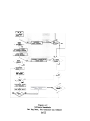
Pressing
the +/INC switch will
cause the displayed
baud rate
to be selected
and the 580B to show the selected
format
on the
top line
and the baud rate
on the bottom
line.
Pressing
the
-/CRSR
switch
instead
will
cause the next
lowest
baud rate
to be
displayed.
2.8
BATTERYI CHARGER
The model 5808 uses a 1.2 amp hour lead acid
(gel cell)
battery.
There is protection
circuitry
potted directly
on top of
the battery.
The battery
is rechargeable
with the charger
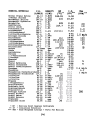
provided
with
the instrument.
The charger
is regulated
so that
there
is no danger of "over charging"
the battery.
It is suggested that the 5808 be charged over the weekend (as well as each
evening)
during
periods
of heavy usage in order to ensure maximum
battery
charge.
2-17
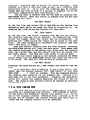
SECTION III
ROUTINE
MAINTENANCE
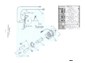
The routine
maintenance
of the 580B involves
the calibration
of the instrument,
the cleaning
of the lamp window,
and the
maintaining
of charge on the battery.
The following
pages give
instructions
for routine
maintenance.
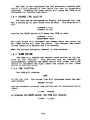
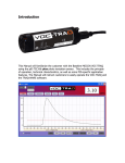
Figure 3.1 illustrates
the
detector
assembly.
3.1
LAMP INSERTION
AND REMOVAL
3.1..1.
REMOVAL
NOTE:
The 580B must be off
while
removing
the
lamp.
In order
to remove the lamp the four
screws
which
hold
the
case top and bottom
together
must first
be loosened.
The case
bottom
should
be placed
flat
on the table
and the top placed
on its
side next to the bottom.
The high voltage
power supply
is removed next by loosening
the
thumb screws on each side and then pulling
the power supply
towards
the rear
of the instrument
(see figure
3.1).
The lamp may now be
removed by loosening
the lamp nut.
3..1.2
INSERTION
Insertion
of the lamp is accomplished
by performing
the above
tasks in the reverse order.
The lamp should be placed flat
against
the o-ring
and the lamp nut fastened
down in order to create
a
proper seal.
The high voltage power supply should then be inserted
and the
thumb screws
fastened
down.
There
are three
pins
protruding
from the high voltage
power supply which should
fit
snugly
into
connectors
located
beneath the detector.
The lamp
spring
(mounted in the center
of the high voltage
power supply)
should make contact
with the lamp ring.
3.1..3
LAMP CLEANING
On occasion
the
lamp should
be removed
for
cleaning.
Cleaning
of the lamp is accomplished
by cleaning
the lamp
surface
of the UV lamp.
The procedures
for cleaning
the
different
lamps are as follows:
3.1.3.1
LAMP CLEANING
METHOD FOR 10.6
eV OR LESS
This is accomplished
by using the Aluminum Oxide scouring
powder provided
with the 580.
First
place a small amount
of Aluminum
Oxide scouring
powder on the lens of the UV
lamp.
Next gently
scour
the lens
surface
with
a soft
tissue
or cloth.
Scour the lens in a rotary
type motion.
3-1
After
scouring
the
lens
surface,
gently
blow
the
remaining
powder from the lens.
Follow
this
with
an
alcohol
or acetone rinse,
and then wipe dry with a soft
tissue.
The lamp is now able to be inserted
into
the
detector.
3.1..3.2
LAMP CLEANING METHOD FOR ~~.7
eV OR MORE
This is accomplished
by gently
polishing
the surface
of
the window with
anhydrous
alcohol
on a cotton
swab,
followed
by an anhydrous methanol or ethanol
rinse,
and
then wiping
dry with a soft
tissue.
Do not allow
the
alcohol
to remain on the surface as it will
leave a film.
stubborn
films
may require
multiple
cleanings
for
complete
removal.
The lamp is now able to be inserted
into the detector.
3-2
~
~
0
.,
8°.
~-.
ii~'8E'~I'~
-.
1111~=il;11
~-N""~."'..
e
,
~
2 11
~
1~
~
;E'~l~~f;
3-3
:c
i
*
3.2
CALIBRATION
NOTB: Chapter
four should
order
to gain
a better
calibration
of the 580B.
be read before
understanding
calibrating
the
of the concepts
580B in
behind
The following
is a brief
discussion
of calibration
as it
relates
to different
lamps.
One of the parameters
in the Parameters mode (see Section
2.4) allows selection
of lamp setting.
The
two types of lamps are the 10.0 eVand the 11.8 eV lamp.
Whenever
a new lamp is used the 580B must be calibrated.
This is true even
if the new lamp is the same type,
e.q.,
the new and old lamp are
both 10.0 eVe This is due to the fact that each lamp will
have a
slightly
different
sensitivity.
It is important
to note that the 11.8 eV lamp will
in qeneral
be less sensitive
than the 10.0 eV lamp.
This is true despite
the
hiqher
energy level
of the 11.8 eV lamp.
The 11.8 eV lamp will
however "see" certain
gases which the 10.0 eV lamp will
not.
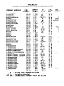
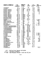
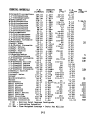
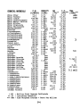
See
Table E.1 for a list
of common organic vapors and their
associated
ionization
potentials.
Any questions
reqarding
the use of the 580B
should be directed
to Environmental
Instruments
Company Application
Laboratory.
The 580B is quite simple to calibrate.
A source of "zero air"
and "span gas" are all that is needed to calibrate
the 580B.
The zero air is introduced
to the 580B in order to determine
the "background"
signal.
The concentration
of the span qas is then
selected.
The span gas is finally
introduced
to the 580B.
The
instrument
makes all
of the necessary
calculations
(including
linearization)
to arrive
at a "calibration
constant..,
When in the
Run mode the signal
is multiplied
by the calibration
constant
in
order to arrive
at the current
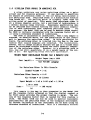
PPM.
SPAN PPM
CALIBRATION
CONSTANT
=
SPAN SIGNAL
PPM =
(SPAN SIGNAL
ZERO SIGNAL)
-
ZERO SIGNAL
CALIBRATION
CONSTANT
NOTB: The PPM is then multiplied
by the RESPONSE FACTOR before
being displayed.
Chapter four explains
the use of response factors
when calibrating.
Section 2.4.8 gives a detailed
explanation
of which buttons to
press in order to calibrate
the 580B.
The flow chart
at the back
of this manual may also be helpful.
CHARGE
When there
is a flashing
"B"
display
(while
in the run mode) the
recharged
by plugging
the charger
rear of the 580B.
The instrument
3-4
in the lower left
corner of the
battery
is low.
The battery
is
into the RUN/CHARGE plug at the
runs while it is charging.
SECTION IV
CALIBRATION
GENERAL
The Model 580B Organic Vapor Meter is indeed a quantitative
instrument
and can certainly
be used as such.
It makes use of
the Photoionization
Detection
System using a lamp with an ionization
energy
of 10.0 eV which
is standard
in the Model 580B.
Almost
all
organic
materials
will
be ionized
at this
energy
level.
There are some organic
materials,
such as a few of the
freons,
methane, ethane and propane that are not ionized
and thus
will
not be detected.
The ionization
potentials
for the various
organic
materials
will
simply
tell
whether the material
will
be
detected
by the Photoionization
Detector.
It does not give any
clue as to the sensitivity
of the detector
for that
particular
material.
certainly,
different
organic
vapors will
have different sensitivities.
It is.important
to understand
that the Model
580B does indeed sense most organic
vapors and that
its response
to these different
organic
vapors will
be different.
In this
section
of the manual,
the aspects
of calibrating
the Model 580B for various
vapors
will
be discussed.
In the
following
section
discussing
applications,
various
ways of using
the features
of the Model 580B will
be explained
along with the
various
methods for calibration
of the 580B.
There will
also be
applications
of the Mode"l 580B in specific
instances
where the
organic
vapors or the mixtures
of organic
vapors are completely
unknown.
The 580B can be an extremely
useful
tool,
even in areas
such as those.
FACTORYCALIBRATION TEST OF THE MODEL580B
The Model 580B has been tested
for calibration
and linearity
tested
at the factory.
The particular
gas chosen for this
calibration
is isobutylene.
The Model 580B has good response
for
isobutylene.
Isobutylene
standards
prepared in air are relatively stable
with time, undergoing
no serious
adsorption
or reaction
problems.
The test
information
is included
in the instrument
packet.
In addition
to the above test a benzene standard
is also
run.
It is important
to note that the instrument
was not calibrated.
It was tested
for calibration.
Therefore,
it should be
calibrated
by the operator
before use.
4.3
METHODSOF GENERATINGCONCENTRATIONSOF VARIOUS
MATERIALS IN AIR
This section
is not intended
to be all
inclusive
as far as
the preparation
of gas and vapor standards
in air are concerned.
Only those methods that
have been found most practical
for the
calibration
of the 580B are discussed
here.
There are basically
two types of standards,
cylinder
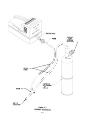
and bag.
4-1
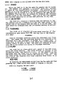
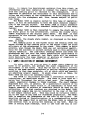
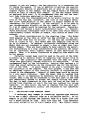
DETECTORINlEr
PROBE
CONSTANT
FlOW
PRESSURE
REGULATOR
~c..::-'c
TEflON
TUBING
/
/
I
COMPRESSED
~
G.A.s STANDARD
OR
ZERO AIR
TEFlON-r
~I~
-./
VENTTO
ATMOSPHERE
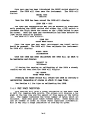
Figure 4.1
Cylinder Calibration
4-2
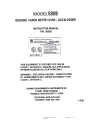
4.3.1
CYLINDER STANDARDS
Certainly
commercially
available
standard
cylinders
of
gaseous materials
in air
offer
the most convenient
method of
calibration.
However,
these are static
standards.
Standards
prepared
in this
fashion
in air
for vapors
of various
organic
liquids
often
show concentration
reduction
with
time due to
adsorption
problems.
In general,
gases when mixed with air will
maintain
their
concentrations
with
time since
adsorption
is
generally
not a problem.
However, some gases are sufficiently
reactive
that chemical
reaction
of the gas will
cause a reduction
of it in air.
These
precautions
must be observed
when using
commercially
prepared
standards
for calibration
of the Model 580B.
It is for this
reason that isobutylene
in air was chosen as a reference
standard
for factory
calibration.
TEl offers
a cylinder
standard
which
includes
both zero and isobutylene
standards.
A constant
flow
pressure
regulator
sets the flow needed for calibration
of the
580B.
Figure 4.1 illustrates
the physical
calibration
procedure.
The inlet
to the 580B is connected
to the "T" as shown.
It is
important
that this
connection
is tangent
to the gas flow.
The
"T" is connected
to the regulator
on the standard
cylinder.
It
is important
that
a length
of tubing
is attached
to the "T"
location.
This prevents
diffusion
of ambient
air
into
sample
line.
The regulator
and tubing
assembly will
have to be moved
between both the zero air and standard
cylinder.
4.3.2
BAG STANDARDS(ISOBUTYLENE)
8ag standards
can be prepared
in a laboratory
and in general
are reasonable
ways of calibrating
the Model 5808.
However, it
is important
that
these standards
be used shortly
after
their
preparation
to reduce the significance
of any adsorption
problems.
static
standards
prepared
for calibration
of the Model
5808 are best prepared
in collapsible
plastic
bags.
This
is
opposed to a fixed
volume container.
The sampling
rate of the
5808, which is 500 ml/min,
requires
an appreciable
amount of
sample.
Even one minute's
sampling out of a fixed
container
will
remove 500 ml/min from it.
This should not significantly
reduce
the pressure
inside
the container.
Thus, the collapsible
bag
provides
the best means as opposed to a fixed volume.
A 5 gallon
polyethylene
bag is a convenient
size to use for the preparation
of static
standard.
A tube is inserted
into
the opened end of the bag and the
bag opening then sealed around the tube.
The tube should have a
cutoff
valve or some means of closing
the volume of the bag.
The
volume of air introduced
into the bag must be measured.
This is
most conveniently
measured
by a wet test
meter.
However,
a
source of air
flowing
through
a flow meter can be used if the
flow can be held constant,
then time is a measure of the volume
of the air placed into the bag.
All air is expelled
from the bag
by completely
collapsing
it prior
to connection
to the source of
air.
4-3
It can then be connected to a wet test meter or flow meter
via a short length of rubber tubing hooked to the plastic
tube of
the bag.
The air
flow
is started
into
the bag at a rate
of
approximately
5L/min.
A total
of 10 liters
is a convenient
volume for a 5 gallon
bag.
This would mean approximately
2
minutes for filling
the bag.
Figure 4.2 illustrates
the physical
configuration
needed to develop bag standards.
For gaseous samples, the trace
organic
will
be added via a
glass
hypodermic
syringe.
The 1 cc Tuberculin
syringe
is a
convenient
size.
For an isobutylene
standard,
the 1 cc syringe
is flushed
with pure isobutylene
and then filled
to the 1cc mark.
While the air is flowing
into the plastic
bag, the short piece of
rubber tubing
is pierced
by the needle from the 1 cc syringe
and
the plunger
slowly
depressed such that the 1 cc of isobutylene
is
added to the air flowing
into the plastic
bag.
When 10 liters
of
air have been added to the plastic
bag, the flow is immediately
stopped and the valve on the tube or the closing
clamp is applied
to contain
the air and isobutylene
within
the plastic
bag.
It is
best at this
stage of the procedure
not to rely
solely
on the
diffusion
of isobutylene
to form a uniform
mixture
inside
the
plastic
bag.
Slight
kneading of the plastic
bag will
hasten the
mixing of the isobutylene
in air.
The plastic
tube from the bag
is then connected
to the probe on the Model 580B via a short
length of rubber tubing and the valve on the plastic
tube immediatelyopened.
The Model 580B withdraws
a sample from the bag at
the sampling
rate of 500 ml/min.
Thus, 10 liters
of sample in
the bag will
provide
approximately
20 minutes.
Certainly
the
calibration
of the 580B can be accomplished
in a shorter
period
of time.
The concentration
of isobutylene
in ppm by volume will
be equal
to the sample size,
which was 1 cc, divided
by the
volume of the bag in liters,
which would be 10 liters,
times
1000.
In this particular
instance,
the concentration
would be:
Conc (ppm by Vol)
=
1cc Isobutylene
x 1000
= 100
ppm
10 LAir
4.3.3
BAG STANDARDS(ORGANICS)
On occasion
there
is the need to prepare
standards
other
than the normal calibration
standard.
As mentioned
previously,
isobutylene
was chosen as a standard
because of its
stability.
If other standards
are to be used, it is best to develop a relation of the other standard
to a standard
of known stability
like
isobutylene.
If this
procedure
is followed,
a response
factor
can be developed
by comparing
the other
organic
standard
to
isobutylene
this
technique
will
be discussed
in a later
section.
The following
is a suggested technique
for preparing
other standards.
For organic
materials,
which are normally
liquids
at room
temperature,
the procedure
is essentially
the same except that an
extremely
small
liquid
sample is injected
into
the flowing
air
stream rather
than the gas sample.
This technique
works well
4-S
only for relatively
volatile
orqanic
materials.
The flowinq
air
stream must vaporize
all
of the material
or the calculation
will
be off.
If the material
is not rapidly
volatile
in that
flowinq
air stream,
the liquid
should be injected
throuqh
the surface
of
the plastic
bag.
Immediately
after
withdrawinq
the needle,
the
hole in the plastic
baq should be covered with a piece of plastic
tape.
Again,
significant
kneading
of the bag will
hasten
the
evaporation
of the sample and mixing of the vapor into the air to
provide
ho.ogeneous
samples.
The introduction
of this
sample
into
the 580B is the same as before.
The calculation
of the
concentration
of the vapor in air is a two-step
procedure
whereby
the small volume of liquid
injected
into the air stream and into
the plastic
bag is converted
to a volume of vapor.
This volume
of vapor is then used in the same manner as the volu.e
of gas in
the case of isobutylene.
The following
equations
apply:
Vol ume Vapor
Liquid
(uL ) =
Volume
(ul)
x Liquid
Molecular
The above
(760 torr)
equation
gives
the
and 250 C (77F).
Then:
Concentration
vapor
volume
at
atmospheric
Vapor Volume
(ppm by Volume) -
is
a sample
calculation
Liquid
Air
pressure
CuI
Volume
x 1000
(liters)
benzene:
VolUJDe = 2 ul
=
Benzene Density
Molecular
for
x 24.45
Weight
Air
The following
Density
Weight
0.879
g/cc
Benzene - 78.1
Vol UJDe=
10 Liters
2 x 0.879 x 24.45
~
0.55
u1
Vapor Volume =
Benzene va~r
78.1
0.55
Conc
x 1000
= 55
a
ppm (vol
10
The syringe
used for the measurement of liquids
in this
particular instance
is a small volume-type
such as those manufactured
by
the Hamilton
Company.
A convenient
size syringe
is the 10 microliter
volume.
4-6
4.4
580B CALIBRATION
The following
procedure
is applicable
for both cylinder
and
Bag Standards.
The sequence requires
both Zero gas and Span gas
to be used.
Span gas can be either
contained
as a cylinder
or
bag, in either
case the exact concentration
used must be known.
This concentration
will
be entered
to the 580 when the program
provides
its entry.
With respect
to Zero gas, there are several
choices.
Obviously
a certified
zero air standard
in a cylinder
presents
no problem.
Another choice would be to build
a zero air
standard
in a bag.
This can be simply
accomplished
with
the
set-up
in Figures
4.1 and 4.2 using a charcoal
scrubber
to remove
all
the hydrocarbons
present
in the air.
Charcoal
does not
absorb
Methane;
this
does not cause a problem because the PID
does not respond to it.
Another approach which could be used in
an emergency is to use room air unscrubbed.
This is acceptable
if you know that
there are no hydrocarbons present
or they are exceptionally
low in concentration.
However,
it
is not recommended as a standard
practice.
The
physical
set up for cylinder
calibration
is illustrated
in Figure
4.1; bag calibration
in Figure 4.2.
4.4.1
CALIBRATION ROUTINE
(A) Set-up calibration
assembly with zero
described
in Figures
4.1 and 4.2.
(B) Model 580B set-up and zero calibration.
1.
2.
3.
4.
5.
6.
7.
8.
9.
1.0.
11.
12.
13.
14.
15.
air
cylinder
or bag as
Power-up instrument
using power plug.
Depress ON/OFF Key to ignite
lamp and initiate
sample pump.
Depress MODE/STOREKey.
Depress- /CRSR Key in response to LOG THIS VALUE? Prompt.
Depress-/CRSR Key to select
Parameters Mode from the
Main Menu.
Depress +/INC Key to advance thru the Run Mode selection
parameter
prompt.
Depress
selection
Depress
selection
+/INC Key to advance
parameter
prompt.
+/INC Key to advance
parameter
prompt.
Depress +/INC Key to
parameter
prompt.
Depress +/INC Key to
parameter
prompt.
Depress
Setting
thru
the
Auto
thru
the
Average
advance
thru
the
Alarm
advance
thru
Lamp Selection
thru
Response
+ /INC Key to advance
parameter
prompt.
Logging
Mode
Time
setting
Factor
Depress RESET Key to initiate
calibration
sequence.
Depress-/CRSR Key to decline
restoration
of the backup
calibration.
Connect outlet
of calibration
tubing
assembly to the
Model 5808 Detector
Inlet
as illustrated
in Figure 4.2.
Introduce
Zero Air to Mode1 5808 by opening flow
regulator.
4-7
16.
17.
C)
Depress RESET Key to
Close Flow Requlator.
Span Calibration
tration
of
-
"Zero"
assuming
Model 5808.
that
250 ppm isobutylene
the
the
Span gas has a concen-
following
procedure
is
followed:
18.
19.
20.
21.
22.
23.
24.
25.
26.
27.
28.
Simultaneously
Depress RESET and -/CRSR Keys to
activate
the movable cursor.
Repeat Step 18 until
the cursor is at the ones place.
Simultaneously
Depress RESET and +/INC
Keys to
increment
the ones place value.
Repeat step 20 until
the ones place value reads o.
Repeat step 18 to move cursor to the tens place.
Repeat Step 20 until
the tens place value reads 5.
Repeat Step 18 to move the cursor to the hundreds place.
Repeat Step 20 until
the hundreds place value reads 2.
Repeat Step 18 to move the cursor to the thousands
place.
Repeat Step 20 until
the thousands place value reads o.
The LCD should now read:
SPAN PPM = 0250
"+" TO CONTINUE
29.
30.
31.
3,2.
33.
34.
35.
36.
Depress +/INC to accept the span conc. value.
Connect isobutylene
cylinder
(250 ppm) to calibration
tubing
assembly.
Connect outlet
of calibration
tubing
assembly to the
Model 580B Detector
Inlet.
Introduce
isobutylene
standard
to Model 5808 by opening
flow regulator.
Reset key to "CALIBRATE" Model 580B.
Close Flow Regulator.
Depress + /INC. Key in response to "RESET" TO CALIBRATE
message.
Depress MODE/STOREto return
to the Run Mode.
The instrument
ments.
4.5
has
been
calibrated
and
is
ready
to
make measure-
DETERMINATION
OF RESPONSE
FACTORS
As mentioned
above,
the Model
580 can be calibrated
with
isobutylene
but be set to read correctly,
the concentration
of
another
substance.
This
is done by usinq
the Response
Factor
that
is set in the parameter
routine.
The default
for
the response factor
is 1.0.
The Response Factor
is the number that
is
multiplied
by the measured
concentration
to obtain
the correct
concentration
of the measured
component.
If
the chemical
to be
measured
is less
sensitive
on a PID than the standard,
(usually
isobutylene)
then the Response Factor
is greater
than 1.0.
If it
is more sensitive
than the standard
then the Response
Factor
is
less
than 1.0.
The reason
for
a Response Factor
4-8
is
practicality.
If
it
is
know that
the sample to be measured contains
only benzene and
therefore
the user would like
to read benzene
concentration
directly,
there
are two approaches.
The user could make a bag
standard
daily
of benzene vapor in air
and calibrate
the 580
directly.
Or the Response Factor could be used.
In the latter
case a bag with benzene is made only once for comparison
to a
cylinder
of a stable
standard
(such as isobutylene).
Then daily,
the Model 580 is calibrated
with the cylinder
standard,
a simple
operation
compared to the work of preparing
a bag standard.
As an example,
if the bag containing
55 ppm benzene in air
as prepared
above were measured
in a 580 calibrated
against
isobutylene,
the concentration
might have been read as 91 ppm.
thus the 580 is more sensitive
for benzene than for isobutylene.
The Response Factor
can now be calculated
Response Factor (RF) -
Factor
STD Concentration
580 Readinq
RF
=
as:
55/91
of Factor
-
STD
0.604
When 0.60 is entered
into the 580 as the Response Factor,
580 will
read 55 ppm for the bag.
Now the 580 need only be calibrated
using
an isobutylene
standard
and a Response Factor
of 0.60 to correctly
respond to
the
benzene.
4-9
SECTION V
APPLICATIONS
5.1
GENERAL
This section
discusses
six applications
which were done
on the old model 580.
These applications
are discussed
as they
relate
to the model 580B.
The following
applications
of the
Model 580B are given to show some different
uses and means of
calibration
of the Model 580B in various
practical
applications.
It is certainly
not intended
to be an exhaustive
list
of the uses
of the Model 580B.
In each situation,
the stress
is placed
on
the means of calibration
and the interpretation
of the readout of
the Model 580B.
Since the Photoionization
Detector
responds
to
virtually
all organic
materials
and since its response varies
for
the different
organic
materials,
questions
can certainly
arise as
to just
how the numbers presented
on the digital
display
relate
to anything
meaningful.
These applications
will
hopefully
illustrate
several
ways in which these numbers can be quanti tati ve and
also illustrate
uses of the 580B where accurate
quantitation
may
be impossible.
5.2
VINYL CHLORIDEMONOMER
IN REACTIONVESSELS.
This particular
application
involved
measuring
the vinyl
chloride
content
in vinyl
chloride
polymerization
vessels
following the polymerization
reaction
and the removal
of the polymer
slurry.
Any residual
vinyl
chloride
left
in the reaction
vessel
has to be flushed
and scrubbed prior
to the opening of the vessel.
The vinyl
chloride
content
must be below a certain
prescribed
level
prior
to this
opening.
The reaction
vessel
is
flushed
with
nitrogen
to remove the vinyl
chloride
from the
vessel
and purge it through
the filter
media which remove the
vinyl
chloride
fro.
the nitrogen
stream
for recovery.
During
this
particular
operation,
it is known that vinyl
chloride
monomer comprises
significantly
more than 90% of the entire
organic
material.
In this
instance,
if the Model 580B is calibrated
for
vinyl
chloride
measurement,
indeed the readout will
be virtually
the true vinyl
chloride
concentration
inside
the reactor
vessel.
The nitrogen
exit
stream prior
to the vinyl
chloride
recovery
was
the point
used for the analysis.
Since the plant was a considerable
distance
from the laboratory
and since
the study would require
a significant
period
of
time encompassing
several
weeks, it was decided to calibrate
the
Model 580B with the isobutylen&
reference
standard
and determine
a response
factor
setting
for a vinyl
chloride
standard
in the
laboratory.
with
the response
factor
set
calibrated
with
isobutylene.
The
sented
with
a known
concentration
in nitrogen.
The response
factor
then
set
in
order
for
the
Model
concentration
of
vinyl
chloride
5-1
at 1.0,
the instrument
was
Model
580B was then
preof vinyl
chloride
monomer
for
the vinyl
chloride
was
580B to
read
the
correct
in
the
nitrogen.
Static
standards
of vinyl
chloride
are very
definitely
not stable
with
ti.e
due to the reaction
of the vinyl
chloride
with
itself.
Thus, standards
need to be prepared
fresh
each ti.e
vinyl
chloride
is to be used to calibrate
an instrument.
Since bag preparation,
which was the technique
used for
this
laboratory
calibration
of the 580B, would
have been inprac
tical
at the plant;
the use of a stable
reference
standard
of
isobutylene
was chosen.
Thus,
at the plant
site,
the Model
580B could
be calibrated
using
the isobutylene
standard
fro.
a cylinder.
This of course,
greatly
si.plified
the plant
use of
the Model 580B.
This relationship
to a reference
standard
reduces the time and equipment required
at the plant
such that the
survey
of all
of the reactor
vessels
was co.pleted
in a short
period
of time with the iteas
established
for the nitrogen
flush
of the reactor
vessels prior
to opening the reactor
vessels.
It is important
to note that when the response
factor
setting
was determined
in the laboratory,
nitrogen
was used as the
.atrix
for the bag preparation
of the vinyl
chloride
standard.
If air were used a different
setting
(higher)
would be obtained.
Since the saaple was in a nitrogen
matrix
so should be the standard.
Note also
it is not necessary
to have the isobutylene
standard
in nitrogen.
In addition
to correcting
for differences
in response between isobutylene
and vinyl
chloride,
the response
factor
setting
can also adjust
for the different
readings
in
nitrogen
and air.
5.3
MONITORING ISOLATED PLANT AREAS FOR TOLUENE AND METHYL
ISOBUTYL KETONE.
Two areas of an extensive
plant
operation
were required
to
be monitored
for the levels
of m~thyl
isobutyl
ketone and toluene.
Both of these areas were relatively
isolated.
In one
area,
methyl
isobutyl
ketone was the only solvent
to which the
atmosphere was exposed other than the potential
leaks that might
occur
in process
equipment
in that
same area.
There were no
other
known solvents
in use in that
area and the ventilating
system
in effect
isolated
this
area from other
areas
in the
plant.
In the second area, toluene
had just
very recently
been
substituted
as a solvent
in place of benzene due to the lower TLV
for benzene.
Average workplace
levels
were therefore
needed for
the toluene
concentration
in this
work area.
Again,
toluene
was
the only solvent
in this
area and there
was no other
process
equipment in the immediate area for even possible
leak problems.
Notice
that
in both of these
areas
in the plant,
it
is
certainly
known from the processes
occurring
in that area and its
relative
isolation
from the other
areas in the plant,
exactly
which organic
vapors will
be by far the predominant
vapors in the
workplace
air.
In many instances,
by si.ply
knowing the processes involved
and the chemicals
in use in those
processes,
the
quali tati ve aspects of the environment
can indeed be established
without
the use of instrumentation.
This is one of the most
overlooked
aspects
in establishing
what organic
vapors
are
present
in the environment.
It simply
involves
determining
what
are the possible
organic vapors that can be present.
In general,
this
narrows
it to several
and in many cases,
a single
organic
5-2
vapor.
In these cases, the Model 580B can be calibrated
specifically for these materials
and will
provide
quantitative
data on the
levels
of these materials
in the workplace
environment.
In this
particular
instance,
even though the laboratory
to be used for
the calibration
of the Model 580B was at the plant
site,
it was
desired
to use a single
580B to monitor
both work areas sequentially
and several
times throughout
the course of a single
day.
This was to be done over a period of time to establish
the variations
of both methyl
isobutyl
ketone and the toluene
in these
work areas.
In this
particular
instance,
changing the response
factor
setting
can avoid considerable
calibration
changes, as one
moves from determining
concentrations
of methyl
isobutyl
ketone
to the area where one is measuring
the concentrations
of the
toluene
vapor.
For calibration,
the Model 580B response factor
was set at
1.0 and the instrument
spanned properly
using a known reference
standard
of isobutylene.
The Model 580B was then presented
with
a flowing
air stream containing
toluene vapor as generated
in the
Thermo Electron
Model 360 using a toluene
diffusion
tube.
The
response
factor
was then adjusted
so that
the readout
of the
Model 580B corresponded
to the toluene
concentration
in this
standard.
The Model 580B was then presented
with a flowing
air stream
containing
methyl isobutyl
ketone.
This also was generated
via a
diffusion
tube in the Model 360 Standards Generator.
Once again,
the response factor
was adjusted
so that the digital
display
gave
the correct
reading
for the concentration
for the methyl isobutyl
ketone presented
to the instrument.
with
the instrument
then calibrated
with
the reference
isobutylene
standard
and knowing
the proper
settings
of the
response
factors
for methyl
isobutyl
ketone
and toluene,
the
Model 580B was then ready for its plant
survey.
The area containing
the toluene
was monitored
for a period
of time with the
toluene
levels
as noted by the 580B being recorded.
The response factor
was set for this
toluene
reading.
The
instrument
was then moved directly
to the methyl isobutyl
ketone
area and the response
factor
adjusted
to read methyl. isobutyl
ketone.
The 580B was then able to read directly
the methyl
isobutyl
ketone concentration
in the second
area.
There was the
possibility
of leaks
in process
equipment
in this
particular
area.
The area in general
was surveyed.
If significant
changes
in
the
reading
of
the
5808
were
observed,
the
580B was used
as a
leak sourcing
instrument
as described
in a later
section.
In
this
fashion,
it could
be determined
if some of the varying
concentrations
in this area were indeed coming from a leak in the
process equipment.
During the survey of this particular
area, no
leaks from process equipment were observed,
therefore,
the readings obtained
on the 5808 could indeed be considered
the methyl
isobutyl
ketone concentration
in this particular
area.
Throughout
the survey
of these two workplaces,
the 580B
could
move back and forth
rapidly
due to its
portability
and
could be, in effect,
recalibrated
for each of the two different
vapors by the mere setting
of the response factor.
5-3
5.4 PETROLEUMETHERVAPORSIN WORKSPACE
AIR.
A given
workplace
was using
petroleum
ether
as a paint
solvent
and for cleaning
purposes.
It was desired
to quantitate
the amount of petroleum
ether
in the air being recirculated
in
this
particular
area.
Petroleum
ether is a distillation
fraction
from crude oil.
Its boiling
point
is slightly
lower
than the
boiling
point
of gasoline.
This means that
petroleum
ether
is
not a single
chemical
entity,
but a multitude
of hydrocarbons
in
a certain
boiling
range fraction.
Reasonable quantitative
data
can be obtained
here without
knowing the exact chemical
composition
of each hydrocarbon
that
composes petroleum
ether.
For
this
purpose,
the Model 580B can be used to measure these vapors.
The 580B is initially
calibrated
with the response factor
set at
1.0 using a reference
standard
of isobutylene.
The 580B is calibrated
on isobutylene.
Then a bag sample is
prepared,
as detailed
above, for the quantitation
of the instrument to measure the petroleum
ether.
In this
particular
instance,
the petroleum
ether is injected
into the bag in the same
fashion
that
liquid
samples
are injected.
The calculation,
however,
has to change slightly
because the ppm on a volume basis
cannot be calculated
without
knowing the exact chemical
composition
of the petroleum
ether.
However,
in a situation
such as
this,
one can still
quantitate
it on a weight basis of the solvent in air.
The equations
below show this calculation.
Weiqht
Vapor
(8q)=Liquid
Volume
Weight
Conc (mgjm3) =
Vapor
Air
For Petroleum
Liquid
Petroleum
Vapor
Conc =
Density
Volume
=
Weight
1.98
This
q/ml
(8g x 1000
Volume
In
x Density
liters)
Example:
VolWRe = 3 uL
Ether
Air
Ether
(uL)
x
=
= 10
0.66
liters
3 uL x 0.66
1000
=
198
g/mL
=
1.98
mg
mq/m3
10
This sample in the bag is then presented
to the Model 5808
and the response
factor
adjusted
so that the digital
readout
on
the front
panel provides
the proper
reading
in mq/m3.
The setting
of the response
factor
that
is needed for this
reading
is
noted.
The Model 5808 can now be used to monitor
reasonably
quanti tati vely the petroleum
ether
in the workplace
environment.
Any further
calibration
of the instrument
can be done using the
reference
standard
of isobutylene.
This is a reasonably
accurate
5-4
way of giving
quantitative
information
on the amount of solvent
in air
even though
the results
are not reported
in ppm on a
volume basis.
This technique
can be used in general
when the solvents
are
a mixture
of materials
which in general
will
probably
be petroleum distillation
fractions.
It would certainly
also be used in
the case of gasoline
vapors
in air.
Notice
from the equations
used versus the equations
for determining
the ppm concentration
in bag samples for pure liquids,
the only real thing
missing
is
the molecular
weight
of the material.
It may be possible
to
assume an average molecular
weight
of the solvent
mixture
and
actually
report
a ppm by volume basis.
5.5 LEAK SOURCING
In this
particular
instance,
the Model 580B is to be used
for determining
the presence,
or absence of leaks in a chemical
process plant.
The MOdel 580B is uniquely
adapted to this
particular
operation
due to its
light
weight.
In this
particular
instance,
it is not necessary
to accurately
attempt
to quantitate
the readings
from the Model 580B.
It will
be used simply
to
determine
presence of leaks and to locate these leaks.
The Model 580B is simply
calibrated
against
a reference
standard
of isobutylene
as normal.
No further
calibration
is
used. It is not necessary
to know the particular
chemicals
flowing in the different
pipes or what they are in the various
reaction chambers.
It is only necessary
to know that these materials
will
have some response
on the Photoionization
Detector.
That
is, that their
ionization
potentials
are below the energy of the
lamp.
The standard
probe of the Model 580B, with the 580B fully
operational,
is then simply
moved along the various
pipes
and
reactor
vessels
in the chemical
process.
All seals are traced
clear
around the seal with the end of
the probe.
As one approaches
a leak,
the concentration
of the
organic
materials
in the air being sampled by the Model 580B will
increase
significantly.
The point
of maximum reading
will
indicate the point
of the leaks.
As one moves further
away from the
leak,
the concentration
of the organics
in air
will
certainly
decrease.
In this very rapid
fashion,
the presence of leaks can
be detected
and their
source fairly
accurately
pinpointed
so that
the leak can be repaired.
In many instances,
it
is not necessarily
the workplace
hazards
of these leaks that
is important,
but the economics
of
the chemical
process
itself.
In this
instance,
as in many instances,
the exact composition
of the organic
materials
being
measured is really
unimportant
to the successful
use of the 580B
in a specific
application.
Also the exact
numbers that
are
displayed
on the digital
readout of the 580B are unimportant.
It
is only relative
magnitudes
that are important
in this
instance.
5.6
AFTERBURNER
EFFICIENCY
In a particular
coating
process,
the material,
after
been coated,
is passed into
a dryer
where the solvents
coating
are removed.
These solvents
are then vented
5-5
it has
of the
into
a
stack.
To reduce the hydrocarbon
emission
from this
plant,
an
afterburner
had been installed
to combust the organic
solvents
from the coating
prior
to release
to the atmosphere.
It
is
important
to determine
the efficiency
of this
afterburner
and to
follow
the efficiency
of the afterburner
to avoid dumping excess
solvent
into
the atmosphere
and, thus,
become subject
to pollution fines.
The Model 580B is ideally
Again,
it will
be unnecessary
tion
of the coating
solvent.
ized
against
the reference
suited
to this
type of operation.
to know the exact
chemical
composiThe Model 580B is simply
standardstandard
isobutylene
in the usual
fashion.
The Model 580B is then connected
to sample the stack gas in
the dryer
prior
to the afterburner,
noting
the steady
state
number displayed
on the digital
panel meter.
The 580B
is then
connected
to the exhaust
gases
from the stack
following
the
afterburner.
580B,
Again,
the
is noted.
steady
state
number,
as
displayed
on the
Model
The reading
prior
to. the burner
minus the reading
after
the
burner divided
by the reading
prior
to the burner times 100 gives
efficiency
of the afterburner
in the stack.
This number is quite
accurate,
even though the Model 580B was not calibrated
specifically
for the solvents
or solvent
mixture
used in this particular
coating
operation.
The individual
readings
before
and after
the
afterburner
.ay not have the exact quantitative
relationship
to
the actual
amount of material,
but their
ratio
will
be accurate
since
basically
the same chemical
or mixture
of chemicals
is
being measured before and after
the afterburner.
5.7 SAMPLECOLLECTIONOF UNKNOWN
ENVIRONMENTS
The Model 580B can also be used in areas where organics
are
known to be present,
but perhaps
the exact
composition
of the
environment
is not known.
This may be due to several
solvents
being in the same general
workplace
or various
separate
processes
occurring
in that same workplace,
all of which could and possibly
are admitting
organic
vapors.
In plant
areas such as these,
the
Model 580B can still
be extremely
useful.
The 580B is calibrated
against
a reference
standard
of
isobuty1ene,
as .entioned
above.
The 580B is then used as a
survey tool
throughout
the entire
plant
area.
The readings
are
logged,
especially
changes in these readings.
The exact numbers
displayed
will
not, in general,
be a quantitative
measure of the
ppm of the organic
vapor since
it
is impossible
to know what
organic
chemical
or mixture
of chemicals
should be used for the
calibration.
When high readings
are obtained
on the Model 580B,
an evacuated
sample bag can be connected
to the rear of the 580B
at the sample exhaust port.
This bag could be virtually
identical to the type of bag used for standards
preparation.
The Model
580B is sampling
the atmosphere
at the rate of 500 m1/min.
The
detection
system of Photoionization
is a nondestructive
system
such that the sample that is exiting
the Model 580B is indeed the
same material
that
is giving
the readings
on the 580B.
When the
580B is seeing
high readings,
this
is the time the bag is con-
5-6
nected to the rear for sample collection.
The bag, if the same
type is used for sample preparation,
can hold approximately
10
liters
of air sample; which would permit
a sampling
time of 20
minutes.
This bag sample can then be closed on removal from the
580B
and transported
to
a laboratory
for
subsequent
analysis
to
identify
the individual
chemical
compounds present
in the sample
causing
the high readings
and
to ascertain
if the workplace
environment
is harmful at those high readings.
The use of the Model 580B coupled
with the bag collection
ensures that
the sample that
is returned
to the laboratory
for
analysis
is a sample containing
the desired
organic
vapors.
This
is assured because the bag collection
is used only when the Model
580B is detecting
high levels
of organic
vapor in the environment.
This is an instance
of the use of the Model 580B when the
type of organic
vapors are not known and it is desired
to know
them.
The 580B has a very useful
function
even in these areas.
It should be noted that a charcoal
tube could be connected to the
rear of the 580B as well as an evacuated plastic
bag.
The charcoal tube will
pass the bulk of the sample,
which is air,
and
adsorb the organic
vapors.
This charcoal
tube can be returned
to
the lab for subsequent
analysis
for both a qualitative
identification
of the materials
present
as well as a quantitative
measure
of their
levels.
5-7
SECTION VI
COLLECTION TECHNIQUES
6.1
GENERAL
As mentioned
in the Application
Section,
it is possible
to
use the 580B in completely
unknown areas as far as the organic
vapors present
are concerned
and still
obtain
meaningful
data.
One of the techniques
described
here is the use of the 580B as a
means of collecting
the representative
samples for further
identification
in the laboratory
regarding
the specific
organics
that
may be present
in addition
to their
concentrations.
Two techniques
were mentioned
in the section
under
the
heading
"Sample Collection
of Unknown Environments".
One of
these techniques
involves
the use of a bag for collection
and the
other
involves
the use of charcoal
tubes as a means of trapping
organic
vapors.
In this
section,
each of these techniques
will
be explored
in further
depth as to the proper
way of using the
580B to collect
the samples
for subsequent
analysis.
These
collection
techniques
are quite
useful
when one is using
the
Model 580B simply
as a survey
instrument.
When readings
on the
580B become quite
high in certain
areas,
it
is impossible
to
determine
the exact source of the high readings
to perhaps pinpoint
the specific
organic
chemical
giving
rise
to the reading.
One may very well want to identify
what the chemical
or chemical
mixture
is that is providing
the high reading.
This will
have to
be. done with
instrumentation
significantly
more sophisticated
than the Model 580B; namely,
an instrument
that
can provide
specificity
as well as qualitative
identification.
A Gas Chromatograph is such an instrument.
If it is desired
to collect
some of the air
to send to a
laboratory
for further
analysis,
one needs to be sure that
the
proper
samples are taken at the proper time.
This means simply
that one needs to be assured that the sample sent to the laboratory is indeed a sample that has a high concentration
of organic
vapor present
in the sample.
The 580B is used to indicate
the
presence
of the high level
organic
vapors.
The sample then is
gathered
at the exit
port of the 580B when the 580B is reading
high values.
This assures that the sample sent to the laboratory
does indeed
have the high
level
vapors
present
in it.
This
generally
simplifies
the sampling
technique
of the environment
and reduces
the number of samples and, therefore,
the expense
needed to accurately
identify
the organics
present
and to quantitate them in a laboratory.
Two design
features
of the Model 580B make this
type of
operation
possible.
The first
is that
the detection
system
used in the Model 580B is the Photoionization
Detector
which is
basically
a nondestructive
detector.
Thus, the instrument
is
able to sense the organic
vapor using the detector
and virtually
the same concentration
of the same materials
exits
the detector
as entered
it.
This does make it possible
for the collection
of
the exact sample contributing
to the high readings.
6-1
The second
feature
of the 580B that
allows
this
sample
collection
is that a positive
displacement
pumping system is used
to draw the sample
into
the Model 580B.
It is a very simple
procedure
then connect
to the exit
of this
positive
displacement
pu.p and trap
the sample exiting
the 580B after
it has passed
through the detector.
6.2
BAG SAMPLECOLLECTION.
One of the most convenient
ways to sample the environmental
air
is to simply
trap
the entire
air
sample
in a collection
bag.
As discussed
before,
the
bags used for
the
calibration
of the
Model
580B,
as discussed
under
the
Calibration
section,
can
certainly
be used for
collection
of the air
samples.
There
are
several
precautions
that
must be mentioned
immediately
relative
to the use of bag sa8ple
collection.
When a bag has been filled
with
air
that
has organic
vapor
in the air
sample,
the organic
vapor
molecules
will
absorb
onto
the inside
surface
of the bag.
This adsorption
will
begin
i8mediately
on introduction
of the air
into
the
bag.
It
will
continue
to progress
with
time
until
the vapor
molecules
that
adsorb
onto the wall
of the bag are in
equilibrium
with
the vapor
molecules
in the air.
This equilibrium depends
very
strongly
on the bag material
and the
chemical
entity
of the
vapor
itself.
The ambient
temperature
also
has
SODe effect.
As mentioned
under
the Calibration
Procedure,
when one is
preparing
a known vapor
concentration
in a bag, the bag should
be
analyzed
very
rapidly
after
its
preparation
to ensure
proper
calibration
of the inst~ent.
The technique
here is to use the
standard
prepared
in this
fashion
as soon as possible
such that
the adsorption
that
has occurred
is an absolute
minimum amount.
This
adsorption
becomes a bit
more serious
problem
in using
bags
for
sample
collection.
The first
problem
is simply
when one is
reusing
the bag,
one has to be sure that
the sample contained
in
the bag previously
has been completely
desorbed
from the wall.
This,
in general,
can be checked
by using
clean
air
to f ill
a bag
allowing
the bag to set for a short
period
of time,
about
1 hour,
and then
analyzing
the air
in the bag.
If
on using
the 580 to
analyze
this
air,
it
shows measurable
organics,
then
the air
in
the bag should
be dumped and new air
introduced
and allowed
to
set for
the same period
of time.
There
will
be a reduction
of
organic
vapor
on the second go-around.
If
it
is still
too high,
this
procedure
is repeated
until
the bag shows virtually
no organic
vapor.
The bag can
be evacuated and reused.
The other
problem
associated
with
adsorption
and sample
collection
is that
the sample
that
is collected
in the bag must
be analyzed
as soon as possible
after
collection
if
one is going
to determine
quantitatively
the amount of organic
vapor
in that
bag sample.
The longer
the sample stays
in contact
with
the bag,
the greater
the adsorption
will
be of the organic
vapors
on the
surface
of the bag and, therefore,
the lower
the concentration
of
the organic
vapors
in the air
sample.
If one is interested
here in only doing
a qualitative
analysis
of the
organic
vapors,
that
is identify
what
vapors
are
6-2
present
in the air sample, the bag certainly
is a convenient
way
of taking
the sample.
If one in addition
to getting
the qualitative
analysis
desires
to quantitate
one or more of the specific
organic
vapors in the sample, the bag sample should be analyzed
within
an hour of taking
this
sample.
If the bag sample cannot
be analyzed
this
soon, it is recommended that one use the charcoal tube technique
explained
in the next section.
There are two considerations
to be given relative
to the
size of the bag and, therefore,
the size of the sample taken.
The first
consideration
is the amount of sample needed by the
laboratory
for its
analysis.
If the analysis
is to be done by
gas chromatography
directly
on the air sample, in general
only 1
to 5 mL of sample would be required
for the analysis.
Therefore,
this
does not become a major consideration
here.
If,
however,
other analytical
techniques
were to be used that
would require
significantly
higher volumes of sample, this should be taken into
account.
The other
consideration
is the sampling
tiae.
The Model
5808 samples at the rate at which the bag attached
to the exit
port
of the 5808 will
be filled.
If the bag can conveniently
hold 10 liters
of air,
this
means that the sampling time can be
up to 20 minutes.
In general,
collection
techniques
using the
Model 5808 are not intended
to supply a four or eight hour integrated sample.
They are used simply to help identify
the materials contributing
to a high concentration
and possibly
the analysis of individual
toxic
organic
vapors
in that
particular
air
sample.
Thus, a 20 minute limitation
on sampling time should not
be too severe.
Certainly
larger
bags could be used on the exit of the 5808,
allowing
up to several
hours of sampling
time should
this
be
desired.
The difficulty
then becomes that
the bags are quite
large
and physically
become difficult
to manipulate.
It was
recomaended back in the Calibration
Section
that
perhaps a 10
liter
bag would certainly
be the convenient
bag for the calibration of the 5808.
It would appear to be also a convenient
bag
for collection
of the samples.
For this
purpose,
a bag that has
no adsorbed
vapors
on the interior
surface
is evacuated
and
closed to the atmosphere.
Several of these bags could be carried
in a very small container.
When the Model 5808 is reading
high
values,
and it is impossible
to determine
the source of the high
values,
then a bag can be connected to the exit port of the 580S
and immediately
opened to accept
the sample exiting
the 580S.
The bag is kept connected
to this
exit
as long as the 5808 is
giving
high readings
or until
the bag has reached
its
volume
capacity.
At this
point,
the bag is removed from the exit
port
of the 5808, immediately
closed,
and returned
to the laboratory
for analysis.
6.3
COLLECTION
USINGCHARCOAL
TUBES
A technique very common in industrial
hygiene-type
analysis
is to use a small charcoal
tube as a collection
device.
An air
sample is pulled
through
the charcoal
tube at a known flow rate
for a known period
of time.
This flow rate and
time determine
the total
volume of air or total
sa.ple
size.
The organic
vapors
6-3
in the air are adsorbed
on the charcoal
in the tube.
These
vapors
are then desorbed
from the charcoal
by adding
a known
volume of desorbing
solvent,
usually
carbon
disulfide.
The
organics
end up in the carbon disulfide.
The carbon disulfide
is
then injected
into
a gas chromatograph
using
Flame Ionization
Detection.
The individual
organic
vapors can then be identified
and quantitated.
The usual charcoal
tubes that are used for this
type of work
contain
two sections.
One section
has approximately
100 milligrams of charcoal
and a backup section
has 50 milligrams.
The
backup section
is analyzed
separately
from the main section
to
determine
if there
is organic
vapor breakthrough
in the main
section.
These particular
size tubes have a recommended maximum
flow in the neighborhood
of 250 to 300 mL/min.
The exit
of the
Model 580 is at 500 mL/min.
The most advantageous
way of using a
smaller
charcoal
tube would be to split
the exit
stream and pass
it through two parallel
charcoal
tubes.
This would give approximately
250 mL through
each tube.
For analysis
purposes,
the
charcoal
of each tube is removed and combined using double
the
amount of sol vent that would be required
for a single
tube.
The amount of total
air that can be passed through
charcoal
tubes certainly
depends on the concentration
of organic
vapor in
the air.
It also depends to some extent on the particular
organic vapor.
In general,
a total
sample through
the smaller
charcoal tube of 10 liters
is a reasonably
safe number to use.
Since
the flow is split
exiting
the 580B using the smaller
charcoal
tubes,
only 250 ml/min is going through the tube.
It would take
40 minutes
to accumulate
10 liters
passing
through
each of the
tubes.
There are charcoal
tubes available
in the marketplace
containing
300 milligrams
of charcoal
in the front
section
and
150 milligrams
of charcoal
in the rear section.
These tubes have
correspondingly
larger
diameter
and can accommodate higher
volumetric
throughputs.
One of these tubes could be hooked to the
exit
of the 580B without
doing the split.
Conceivably
since it
contains
3 times the amount of charcoal,
a safe operating
total
volumetric
throughput
would be approximately
30 liters.
This
would be a full
hour's
operating
time on the Model 580B.
Again,
it must be stressed
that
the 580B when used in the particular
form, is not being used as a personnel
sampler to end up with the
tiBe weighted
average concentration
over an eight
hour period.
The intent
here is to identify
the high level
organics
observed
on the 580B and to quantitate
them following
identification
to
determine
the safe working area.
6-4
SECTIONVII
COMMUNICATION
The 580B provides
a serial
(as
opposed
to
parallel)
communication
port.
There is also a communication
cable provided
for
easy link
up to a serial
printer
or RS-232
port
of a
computer.
Logged
data
may be "dumped"
(sent
through
the
communication
port)
to a serial
printer.
Many of the 580B parameters
may be set by a remote computer by using the serial
port
and the 580B communication
software
(the software
is an option,
part
number 580A-9014).
The serial
Note:
port
is
not
to be used in
a hazardous
location
PRINTER
The 580B can be instructed
to send all
of its
logged
data
through
the serial
port
to a printer
(or a dumb terminal).
The
580B printer
mode should
be selected
(see
Section
2.7.4).The
serial
communication
cable
should
then be plugged
into
the RS-232
port
at the rear
of the instrument
and the other
end of the cable
plugged
into
the
serial
port
of a printer.
The 580B should
finally
be instructed
to output
to the
printer
(see
section
2.7.1).
COMPUTER
The 580B provides
capabilities
for
remote
operation.
Appendix A includes
a detailed
technical
explanation
of the 580B
printer
and computer interface
protocol.
The information
in this
appendix
is sufficient
for custom software
to be developed
for
interfacing
to the 580B.
Thermo Environmental
however
has
developed
communication
software
which implements
all
of the
available
communication
capabilities
in a simple
"menu driven"
format.
Remote communication
may also be accomplished
by using
generic
communication
software
package such as CrossTalk.
Appendix A will
be helpful
if this route is taken.
NOTE: Generally,
the RS-232 port on an IBM PC (or compatible)
is
a male connector.
Since the communication
cable provided
with
the 580B is also male, a "gender
changer"
(a DB-25 connector
which converts
from male to female) is needed.
7.3
COMMUNICATION
SOFTWARE
(OPTIONAL)
There is communication
software
available
which will
run on
an IBM PC or compatible.
The software
provides
the capability
of
obtaining
or changing
the 580B parameters
(alarm
setting,
response factor,
or operating
mode to name a few).
Logged data
may be stored to disk or printed
to a parallel
printer.
Concentrations
may be read and displayed
on the computer screen.
There
are a few operations
which may not be accomplished
remotely
(for
obvious
reasons).
The lamp may not be changed remotely.
The
lamp and pump may not be turned on from the computer either.
7-1
NOTE: The communication
software
will
attached
via the communication
cable.
7.3.1
not
work unless
the
5808 is
HOWTO GUIDE FOR COMMUNICATIONSOFTWARE
11.
The 5808 must be turned
on and connected
RS-232 port.
The 5808 must be in the computer
default
setting).
to the computer's
mode (this
is the
The floppy
disk should. be inserted
into the co.puter.
Type
580B (this
software
was originally
developed
for the 580B) and
then hit return.
The introduction
screen wi 11 appear.
12.
13.
The software
some other
580B.
defaults
baud rate
#4.
After
selection
menu will
appear.
is
of
to
2400 baud (as does the
desired
the
it
baud
must match
the
rate
return.
press
580B).
setting
If
on the
The main
HOTE: If the computer's
screen goes blank and the main menu does
not appear,
then there is a problem with the communication
link.
Check to be sure that the communication
cable is plugged into the
RS-232 port and that the 580B is on.
7-2
SECTIONVIII
FLOW CHART
There are two flow charts
which illustrate
the structure
of
the 580B software.
The first
is a "Quick start-up"
flow chart.
Much of the detail
is not included
in this flow chart in order to
diagram
the basic
structure
of the software.
The second flow
chart
includes
extensive
detail
of each screen and the function
of the seven buttons.
These flow charts
provide
an easy method
for
determining
how to get at each of the many facilities
provided
by the 580B.
8.1
QUICKSTART-UP
The Quick
start-up
flow
chart
shows each of
the
top
level
screens.
The screens
are ordered
according
to the hierarchy
of
the
580B software.
The particular
button
(which
advanced
the
580B to the
next
screen)
is shown in parenthesis
above
each
screen.
This
flow
chart
does
not
illustrate
any
of
the
associated
screens
or operations
(see the detailed
flow chart
for
more in depth
information).
The Quick
start-up
flow
chart
should
be fully
understood
before
moving
on to the more detailed
flow
chart.
The best
way
to learn
each of the flow charts
is to have the 580B with
you and
to follow
along verifying
each step.
8.2
DETAILEDFLOWCHART
The detailed
flow chart illustrates
many of the lower level
screens as well as the function
of buttons.
Screens are shown in
rectangles
with the text written
inside.
The buttons
are shown
in ellipses
(actually
a rather
flattened
ellipse)
with the button
identifier
written
inside.
There are a few conventions
which
need to be explained.
The button
identifiers
have been abbreviated.
For example the +jINC button is simply denoted as +.
When
two buttons
need to be pressed simultaneously
each identifier
is
shown with a slash between them.
For example RESETj+ indicates
that
the .RESET and +jINC buttons
should
be pressed
together.
Arrows
indicate
the direction
of flow from one screen
to the
next.
~l
1
L~
!
!
OUT
2
~
tQ.D
~
- 181
- 181.2
I
(~/$T~)
-
'3
R/CC»-.
+/~SS
J\A. 27.87
1431
-RESET- TO CtG
(-/CR$R)
~
(+/1":)
.14563979
1.0..
- RESET-TO CHG
~.
fETD
"RESn- TO CHG
(+/(~)
MlTO LOGGltG
-RESET- TO CHa.
(+"I~)
(+/I.c)
-
I HSTR
..
~TM
-.- - YES
-RESET-
588M8
Tt) ~
I C-~)
ca.uTD
24M~
2. (-/CRSR)
(+/I~)
(--'CR8)
LOG MTM
-+- - 'tE$
RESET
~
~L£\6.3
-RESET- TO ctG
-.- - YES
01..
-
--"PMNt
S/Q..OCK
~ICATE?
~
1
181.2
~
(+/ltCl
(RESET)
(SPtCR)
181.2
L~.C«IE
-
-
.
~
-
[
LOG THIS ~tE?
~
181.2
(-/CRSR)
"""'"
LOC
. ~
:
-RESET-
TO ~.
~
-
-RES£T-
TO CHa.
(+/I.c)
F~T
e.el
(+/ItC)
1
Tt£ T)«££ SCR£ENS I N Tt£ 8O)<ED MEft REPRESENT Tt£ ~
PI(K)E s~
I ,. T)£ LN'P I S ~T LIT n£H SCREEN Ot£
WILL BE EHMLEO.
~
T)£ LN'P IS LIT SCREEN T~ OR
n«EE WILL BE DNI..ED ~
I ~ ~ T)£ T)£ aMREHT
~TI"~.
I,. Tt£ ~
~TI~
~
IS MX
tQ.D n£H SCR£EH ~
WILL BE DNLED.
OTt£RWISE
SCREEN Tt«EE WILL BE Et8LEO.
T)£ ~TI~
~
IS
SELECTED IN T)£ ~MN£TERS
SECTI~.
~
.
2. Tt£ s.-
I
~
18.EV
.
S c.-£Rft T I ~ PMH£TER$
ME: M.J.. CGtT ~ I NED I N
THIS SECTI~.
ft BRIEF MSCRIPTI~
~ ~
~
IS GI~N 8EI.~.
OPERftTING ~
. MX t«»L.D OR ~
COHCEHTRftTI~ PETER
MlTO LOOGING
. MIT~TICM.LY
STORES (LOGS) DftTft ~T PRESET I~
MDMING
INTERUM. . ~
~
SE~
~ TO F~
"1.aJT£S
H..Mtt SETT I ~
. M.Mn WILL ~
~
M.Mtt L£\8.
IS ~
LNP SETTI~
. SELECTS 18.8 OR 11.8 EV ~
(SERIM. ER
M.SO)
RESPC»tSEFftCTOR
. CORRELATES Nt ORGH4IC TO n£ CM.IBRftTI~
~
CM.I~TI~
. SECTI~
.-ERE s.IS CM.I~TEO
FREE SPfICE
'3
~
. I~I~TI~
~
1..
ftT
NQMT ~
~
LEFT ~
T)£SE ME Tt£ SCRI:EHS USED FOR LOGGING (STORI~)
DftTft
POINTS.
N'"TER ENTERING T": DESIRED LOCftTI~
COM.
SI~Y
~SING
T)£ ~I'ST~
SWITCH WILL LOG ~
\W.~
(lIS ~
lIS ft DftTE MG TIPE STNP) MG ~
~TI~
TO T)£ Rt-. ~.
THE ftCCESS (SECURITY) LEVEL IS SET IN THIS SECTI~.
ACCESS L£\8.
T)«££ GI~$
T)£ ~TOR
~SS
TO M.J.. ~
Tt£ s.-'S
FftCILITIES.
L~
~SS
u:WL. ZERO ME:
PROGR£S$I~Y
IUE RESTRICTI~.
ftCCESS u:WL. ZERO
o.LY M.LOW ~I~
HC) LOGGING ~ DftTft.
Figure 8.1
Quick Flow Chart
8-2
DftT~ ST~
(+/ltC)
eeeeee
..
k
.
N \5
=~
,,~
'"
~1
~-=
..
&
-
-
~,
~
'~I
I ~~
~f
u
II!
i~i
,~
(W\
.
APPENDIXA
COMMUNICATION
A.l
INTRODUCTION
The 580B is capable
of communicating
over an RS-232 link
with
any peripheral
device
which adheres
to the communication
protocol
outlined
in this
document.
The 580B will
communicate
with
a peripheral
device
in one of two modes.
While
in the
PRINTER mode the 580B responds
to commands from its
keypad and
can be commanded to send characters
out its
RS-232 port
to a
peripheral
device.
In the COMPUTERmode the 580B responds
to
commands from a peripheral
computer and can be commanded to send
and receive
data and to perform
other tasks.
Regardless
of the
mode used, the 580B sends and expects
to receive
data in the
following
format:
No Parity
1 start
Bit
8 Data Bits
1 stop Bit
Baud Rate
= 150,
300,
600,
1200,
The Baud Rate may be selected
Section
2.7)
2400,4800
from the
or 9600
580B keypad
(see
A.2 PRINTERMODEINTERFACE
log
In the PRINTER mode the
data
out the RS-232 port
580B can be instructed
to send its
to a peripheral
device
such as a
printer.
The 580B can be manually
instructed
from its
keypad
to
output
its
log data.
In this
case the 580B sends all
the log
data points
it has acquired
thus far.
The log data is saved in
580B memory and will
NOT be automatically
erased upon output.
While in the PRINTER mode, the 580B log data file
must be erased
(reset)
from the keypad.
An example of a log data output
is
shown on page A-I7.
Notice
that
the 580B also
sends header
information
which includes
the following
parameters:
instrument
number, user ID, and mode of operation.
The date at the top of
the header corresponds
to the time when the first
log data point
was taken with the parameters
set as shown in the header.
If any
of the parameters
are changed and then new log data points
are
acquired,
the 580B will
send an updated header before
it sends
the new data points.
It is also important
to note that every log
data point
is time stamped to show when it was stored.
A-I
HARDWARE
INTERFACE, PRINTERMODE
580B
PERIPHERAL
TxD (8)
CTS (E)
GND (A)
)RxD
-.DTR
GND
(or
"printer
ready")
The connections
shown above are required
before the 5808 can
successfully
send its log data to the peripheral.
An example of
a cable used for PRINTER MODE communication
is shown below:
SAMPLE CABLE,
580B
TxD
CTS
GND
GND
5808
TO HP THIKKJET
PRINTER
PRINTER
(B)
(E)
(A)
(F)
Thinkjet
connector
= TRWjCINCH
DB-25P
plug connector
Please remember that the 5808 must be placed
ER mode prior
to output
of log data to a printer.
from the 5808 keypad.
into the PRINTThis is done
HARDWAREHANDSHAKING, PRINTER MODE
The 5808 will
send loq data out the port
to a peripheral
device as lonq as its CTS line
is asserted
(+V).
If the peripheral has temporarily
fallen
behind,
and consequently
clears
its
DTR line
(-V),
the 5808 will
stop transmittinq
data.
It will
resume transmittinq
as soon as the peripheral
reasserts
(+V) its
DTR line.
A.3 COMPUTER
MODEINTERFACE
In the COMPUTERmode the 580B will
respond to commandssent
by a peripheral
computer.
The 580B will
respond to 3 types of
commands; DO, GET, and SET commands.
An example of a DO command is "DO RESET LOG (ret)"
in which
the 580B is instructed
to reset its log which,
in effect,
clears
all previously
stored
log data points.
. ,
A GET command such as "GET ALARM (ret)"
allows the peripheral to change a specified
paraaeter
in the 580B to a value provided by the peripheral.
A combination
of DO, SET, and GET commands allow the operator at the peripheral
to perform a variety
of functions
needed to
prepare a 580B for acquiring
data.
The 580B can also be operated under "computer control".
For
example, the 580B can be co..anded
to acquire
readings
at specified
intervals
and then store
the readings
in a log data file.
A-2
The 580B can subsequently
printer,
a file
or the
can all
be accomplished
computer.
So, effectively
be commanded to send its
log data to a
screen
of the peripheral
computer.
This
through
commands issued
by the peripheral
the 580B is under
"computer
control".
HARDWAREINTERFACE, COMPUTERMODE
580B
COMPUTER
TxD (B),
RxD (C)
CTS (E)
GND (A)
CTS
!-RTS
The connections
shown above are required
before the peripheral
computer
can successfully
communicate
with
the 580B.
In
addition,
the 580B must be placed
into
COMPUTERmode.
This is
done from the 580B keypad.
is
An example
shown below:
SAMPLE CABLE,
of
a cable
used
for
COMPUTER MODE communication
580B TO IBM PC
5808
COMPUTER
(3)
(2)
20)
(6)
GND (A)
GND
GND
7)
1)
CTS
!-RTS
(5)
1
(4)
If the peripheral's
DTR line is asserted
(+V), the 5808 will
look for and then respond to peripheral
commands. As long as DTR
remains high,
the 5808 will
NOT perform
functions
such as counting,
updating
the display,
storing
log data,
etc.
If DTR is
asserted,
the 5808 will
display
the following
message:
-COMPUTER
"WAITING
LINK"
FOR CONN"
The 580B must be allowed
lOOms between the time the peripheral asserts
DTR and the time it sends the 580B its
first
message.
If the 580B is busy communicating
the display
will
read:
A-3
"COMPUTER LDfK-
"COMMUNICATINGWhen DTR is low (-V),
the 580B will
mode of operation
where it counts,
updates
will
NOT respond to peripheral
commands.
XON/XOFF
HAHDSHAKIIfG,
COKf'u'.l'~
return
to its
normal
the display,
etc.
and
MODE
If the
5808 is transmitting
log data
and detects
that
an
XOFF has been received,
it will
stop transmitting.
The 5808 will
not resume transmission
until
the peripheral
device
sends
XON.
The 5808 will
respond
to XON and XOFF characters
only
if
it
is
NOT communicating
with
the
computer
(i.e.,
if
5808 CTS is NOT
asserted).
It is important
to note that
if the 5808 receives
an XOFF it
will
stop transmitting
and will
simply wait for the peripheral
to
send XON, it will
not acquire
data, update the display
or perfor.
other functions.
The 5808 is essentially
"locked
up" until
it
receives
XON.
For this
reason,
it would be good programming
practice
to send out an XON to the 5808 prior
to 580Bjperipheral
communication
and afterwards
also.
consequently,
if
an XOFF
character
is sent to the 5808 inadvertently,
the 5808 will
not be
locked up indefinitely.
PERIPHERAL/58GB COMMANDMESSAGES
A command message is a string
of upper-case
ASCII characters
terminated
by an ASCII carriage
return.
The carriage
return
may
immediately
follow
the command or a space may separate
the command and the carriage
return
as shown in the example below.
The
command messages which the 580B will
accept
from the peripheral
are listed
in TABLE A.l.
The 580B will
accept the messages as
shown in TABLE 1 or the command portion
of the message can be
abbreviated
as follows:
WS R F 01.00
(ret)W
instead
wSET RESPONSEFACTOR 01.00
of
(ret)W
Please note that
the abbreviation
letter
of each and every word of the
additional
guidelines
for
abbreviating
commands.
must contain
the first
command.
There are some
the SET OPERATING MODE
If the abbreviated
version
of a command is sent,
an ASCII blank must separate
each letter
of the command and must
separate
the command from the data.
Note that the command message will
contain
data only if a SET command is being sent.
If the spelled-out
version
of a command is sent,
an ASCII
blank must separate
each word of the command and must separate
the command from the data.
Every SET command message contains
a data value.
The data
sent as part
of a SET command must con for.
to the formats
described
in TABLE A.l.
It is important
to note that the 580B does
NOT perform error-checking
on data sent as part of a SET command.
A-4
It is up to the user to insure
that the
bIen and formatted
as shown in TABLE A.I.
The following
are examples
"SET
ACCESS LEVEL
or
"S A L 3 (ret)
of valid
3 ( ret)
value
is
"reasona-
command messages:
II
II
"SET REAL TIME 02/15/86
or
data
"5 R T 02/15/86
1723
(ret)"
1723 (ret)"
580B/PERIPHERALRESPONSEMESSAGES
A response message is a string
of upper-case
ASCII characters terminated
by an ASCII carriage
return.
The response messages which the 580B will
send to the peripheral
are listed
in
TABLE A.I.
The messages which the 580B sends in response
to a
GET command contain
data formatted
as shown.
The notes which
follow
TABLE A.l describe
the GET command response
messages in
more detail.
SOFTWARE
HANDSHAKING,COMPUTER
MODE
Every
command message
must be preceded
by the
"WAKE
UP/PROCEED" sequence.
This sequence begins when the peripheral
sends a WAKE UP ("?")
character
to the 580B.
The 580B must
respond with a PROCEED ("I")
character
before
the computer
can
send a command message.
In the discussion
to follow,
the WAKE UP/PROCEED sequence will
be referred
to as
(WAKE UP/PROCEED).
The peripheral
sends command messages to the 580B an entire
line at a time.
When the 580B receives
the command line
it will
echo the line back to the peripheral.
The peripheral
will
examine the echo to determine
if the 580B received
the command correctly.
If the echo was correct,
the peripheral
will
signal
the
580B with the PROCEEDcharacter.
The 580B will
then perform the
task specified
by the command message.
In the discussion
ahead,
the command message and echo sequence
will
be referred
to as
(COMMAND/ECHO/PROCEED).
The software
handshaking
sequences for each of the 3 types
of commands are given below:
00
COMMANDS
The handshake
1.
2.
3.
4.
will
the
sequence
for
a DO command is
as follows:
(WAKE UP/PROCEED)
(COMMANDS/ECHO/PROCEED)
580B performs
task
580B sends
PROCEED or ERR
If the 580B was able to
send a PROCEEDcharacter
error
message ("ERR").
successfully
in step 4,
A-5
complete
otherwise
the task it
it will
send
GET COMMANDS
The handshake sequence below applies
to all
of the GET
commands with the exception
of GET LOG DATA and GET CONTINUED
LOG:
1.
2.
3.
4.
5.
(WAKE UP/PROCEED)
(COMMAND/ECHO/PROCEED)
5808 sends data message
Peripheral
echoes data message
5808 sends PROCEEDor ERR
The message sent by the 580B in response
to a GET command
are shown in TABLE 1.
When the peripheral
receives
the message
containing
the data it echoes the entire
message back to the
580B.
If the echo is correct
the 580B will
send the PROCEED
character
so that
the peripheral
knows it received
the data
correctly.
If the echo is not correct,
the 580B will
send "ERR".
The GET LOG DATA and GET CONTINUED LOG commands differ
from
the other
GET commands in that
the 580B sends an indefinite
number of data values.
The handshake sequence for these commands
is as follows:
1.
2.
3.
4.
5.
6'.
7.
8.
(WAKE UP/PROCEED)
(COMMAND/ECHO/PROCEED)
580B sends a log data point message
If message = "EOT" (end of transmission)
otherwise
go on to step 5.
Peripheral
echoes entire
message
580B sends PROCEED or ERR
Peripheral
sends PROCEED
Go to step 3
then
DONE,
In step 4, the 5808 sends "EOT" if it has sent all the log
data points
available.
If some time later
the peripheral
sends
"GET CONTINUED LOG (ret)"
the 5808 will
send any additional
data
points
it may have acquired
since the GET LOG DATA command.
In
step
6, the 5808 will
send PROCEED if
the peripheral
echoed th.e
message
correctly
in step
5.
The 5808 will
also
increment
its
data buffer
pointer.
If however,
the peripheral
did ~
correctly
echo the message in step
5, the 5808 will
send "ERR" in step 6
and will
HQr increment
its data buffer
pointer.
This means that
the next time through
step 3, the 580B will
send the same data
point
again.
In either
case, the peripheral
must send a PROCEED
in
step
7.
COMMANDS
handshaking
1.
2.
3.
4.
sequence
for
a SET command is
(WAKE UP/PROCEED)
(COMMAND/ECHO/PROCEED)
5808 sets parameter
to value
5808 sends PROCEED or ERR
A-6
as follows:
In step
3 the 580B sets
the parameter
specified
by the
command to the value provided
by the peripheral
in the command
message.
The data value sent in the SET command message must be
formatted
as shown in TABLE 1.
If the 580B is able to successfully
set the parameter
it will
send the PROCEED character,
otherwise
it will
send "ERR".
NOTE: The flowcharts
shown in
Figures
A.I
-
A.4
are
included
further
explain
the software
handshaking
sequences
required
successful
communication
between
the peripheral
and the 580B.
to
for
TABLE A.1
MESSAGE FORMATS
PERIPHERAL
00
COMMAND
5808
RESPONSE
COMMANDS
DO END COMMUNICATIONS (ret
00 RESET LOG ( ret )
t (ret)
! (ret)
GET COMMANDS
GET
GET
GET
GET
GET
GET
GET
GET
GET
GET
GET
GET
GET
GET
GET
ACCESS LEVEL ( ret)
ALARM SETTING ( ret)
CONTINUED LOG (ret)
INSTRUMENT NUMBER ( ret )
LOCATION CODE ( ret)
LOG DATA (ret)
OPERATING MODE (ret )
MAX READING ( ret)
RATEMETER READING ( ret)
REAL TIME ( ret)
USER ID ( ret)
RESPONSE FACTOR (ret)
SPAN CONCENTRATION (ret)
VERSION NUMBER (ret)
LOGGING INTERVAL (ret)
ACCESS LEVEL
I
(ret)
ALARM SETTING
1111
(ret)
(see notes which follow)
INSTRUMENT I
111111
SET COMMANDS
SET
SET
SET
SET
SET
SET
SET
SET
SET
SET
(ret)
LOCATION CODE
111111 (ret)
(see notes which follow)
OPERATING MODE: ASCII
(50)
(ret)
LAST MAX VALUE 1111 ASCII
(8) (ret)
LAST CONC VALUE 1111 ASCII
(8) (ret)
REAL TIME CLOCK II/II/II
1111 (ret)
USER I.D.
#
111111111
(ret)
RESPONSE FACTOR 11.11
(ret)
SPAN CONCENTRATION 1111 (ret)
580B VERSION 1.0 (ret)
1:11 (ret)
ACCESS LEVEL I ( ret )
ALARM SETTING 1111 (ret)
INSTRUMENT NUMBER 111111 (ret)
LOCATION CODE 111111 (ret)
OPERATING MODE ASCII
(50)
(ret)
REAL TIME 11/11/11/
1111 (ret)
USER ID 111111111
(ret)
RESPONSE FACTOR 11.11
(ret)
SPAN CONCENTRATION 1111 (ret)
LOGGING INTERVAL 1:11 (ret)
A-7
!
!
!
!
!
!
!
!
!
!
(ret)
(ret)
(ret)
(ret)
(ret)
(ret)
(ret)
(ret)
(ret)
(ret)
NOTES ON TABLE A.1
The peripheral
will
receive
data back from the 5808 in
response to a GET command only.
The 5808 response to a DO or SET
command is the PROCEED("1")
character.
This is because the 5808
does not actually
return
data but siqnals
the peripheral
with the
PROCEED character
if it was able to perform the task requested.
If for some reason the 5808 is unable to perform the task it will
send an error message "ERR" rather
than PROCEED.
The data values
sent by the peripheral
as part
of a SET
command message and the data received
by the peripheral
in response to a GET command must be formatted
as shown in TABLE A.I.
The data foraat
codes used in TABLE 1 are described
below:
I
a single
1:1:1:...1:1:
an integer
.string",
l's
shown indicates
the string.
Note:
the length
specified,
if necessary.
number of
the
length
of
the "string"
MUST be
use leading
zeros
an ASCII
n characters
with
ASCII
Cn)
digit
string
Several
of the command messages listed
additional
explanation.
These comments are
the command name:
the
a maximum of
in TABLE 1 require
listed
according
to
DO RESET LOG
All
This command instructs
log data values acquired
the
5808
previously
to clear
will
its
log
be erased.
data
file
GET CONTINUED LOG
This command instructs
the 580B to send any log data points
acquired
since the last GET LOG DATA command.
The foraat
of the
580B response
will
be the same as the response
to the GET LOG
DATA command.
GET LOG DATA
This command instructs
the 580B to send all of its log data
points.
The log data file
is saved in 580B memory and is NOT
automatically
erased
upon output.
The log data file
may be
erased (reset)
with the DO RESET LOG command.
GET OPERATING MODE
The 580B responds to a GET OPERATING MODE command by sending
a string
"MODE: ", followed
by an ASCII string
which describes
the current
580B mode of operation.
The 580B responses
to the
A-8
GET OPERATING MODE command are listed
OPERATING MODE:
OPERATING MODE:
CONCENTRATION
CONCENTRATION
below:
METER NORMAL
METER MAX HOLD
GET MAX READING
The 580B responds
to a GET MAX READING command by sending
the max value as shown in TABLE A.I.
After
the 580B sends the
max reading
it resets the max value to o.
GET REAL TIME
The 580B will
following
format:
return
its real time
"05/29/86
1422"
as an ASCII
string
in the
SET ACCESS LEVEL
The access
level
must be an integer
in the
range
0 to
3
SET INSTRUMENT NUMBER
The instrument
number is a string
of 6 integers.
If the
instrument
number = 2 then the number must be represented
as
000002 (i.e.
leading
zeros must fill
in excess
spaces).
An
example of a valid SET INSTRUMENT NUMBERcommand is "SET INSTRUMENT NUMBER000002 (ret) 'I.
SET LOCATION CODE
The location
code is a string
tion
code - 234 then the correct
"SET LOCATION CODE 000234 (ret)".
excess spaces.)
of 6 integers.
If the locaSET LOCATION CODE command is
(Leading
zeros must fill
SET OPERATING MODE
As shown in TABLE A.l,
the command SET OPERATING MODE must
be followed
by an ASCII string
which describes
the mode.
The
list
of valid
SET OPERATING MODE commands along with valid
abbreviations
are listed
below:
SET OPERATING MODE CONCENTRATION (ret)
S 0 M C (ret)
SET OPERATING MODE MAX HOLD (ret
S 0 M M H (ret)
)
A-9
(
ENTR~
i
PER I PtERN..
SEHOS
"7-
~
~
58W1
RET~
IHC
"I"
MX
RETRIES?
RETRY
C~ER
i
YES
PERI PHERAL SEtOS
DOC~
MESSAGE
~
~
ECHOS
P£SSAGE
~
E~
CORRECT '?
I HCRDENT
T~ISSlc.o.
ERROR ~ER
. ,..~~
MX TRflNS
ERRORS 1
YES
~
I Pt£RM.
$EtC)S
I
==:=:=~~I:~~~~~~:~:~~-,
58M~~
TMK
N-K) S£J4)$
REPLY
REPLY
- -,-
YES
EXIT
T~
REPORT-DOCOI'WWC)
FftIL~
Figure
A.I
Software Handshake
Do Couunands
A-lO
::Y£S
~
(
~RY
)
PERIP~
SE~
"?"
~
NO
58eA
~.I.
fW(
INCREf1ENT
RETRY C~ER
YES
YES
PERI pt£RAL
GET co~
SEtC)S
P£SSAGE
s~
ECHOS
ENTI RE t£SSAGE
NO
ECHO
CORRECT?
~
I HCR£I£NT T~
ERRORC~
MX~
ERRORS ?
I SS I ~
~
YES
YES
PER J Pt£RAL
SENDS.!.
..
I
588ft
SEI-I)S
DATA
I'£SSAGE
,-
EXIT
MTft
EOT
~
PERIPHERAL ECHOS
DATA tESSAGE
S8~
-~
SENDS REPLY
~ TRANS
~ORS
?
...
~
YES
Figure
A.2
Software Handshake
Get Log Data, Get Continue Log Command
A-II
(
EHT~)
I PERI~
soms -?NO
~
~
RE~
"!"
INCREI£HT
R£TRV ~
YES
1M)(
YES
~.
-
PER 1 Pt£RH.
SE)C)S
GETCOt9WI)I£S~
~
-
ECHOS I£SSME
NO
E~
~CT?
MCREJ£HT ~ISSIC»f
~COI.-.T
M)( TRHoIS
ERRORS?
YES
YES
I PERI Pt£RAL SE)C)$ .!.
I SaM SEtC)SDATA t£SSf\GE \
PERl~
ECHOS
OftT~ P£SSME
I ~
'~'.""""~'.'r
SEtC)$ REPLV '
EXIT
REPLY
- -,-
NO
YES
Figure
A.3
Software Handshake
(Except
Get COJmnand
Get Log Data. Get Continue
A-12
Log)
(
~y
P£RI~
)
SOC)S -?-
r
t«)
NO
S8eA
RE~S -,-
[HCREJ£NT TR~
ERROR ~
[SS [ON
YES
MX
PERI Pt£RAL SEt-I>S
SET ~
I1ESSIIGE
, SSM ECHOS t£SSME
~
NO
ECHO
CORRECT?
I t«;R£f£HT T~
ERROR~
I SS I ~
YES
YES
I PERIP~
MX TRN-IS
ERRORS?
SEWS "'"
588ft PERFORMSTASK
HC) ~
REPLY
EXIT
YES
REPLY
- -,"
f«)
REPORT "SET"
COI'II'WoC)
ERROR
Figure
A.4
Software Handshake
Set CODmlands
A-I3
SET REAL TIME
The format
II/II/II
for
setting
the
real
time
is
as follows:
1111
. . . ..
.
.
.
.
.
..
. . . .. . . .minutes
(max=59)
hours (max=23)
. . . . . . . . . . . . . . year
. . . . . . . . . . . . . . . . . day
. . . . . . . . . . . . . . . . . month
For
example:
SET REAL TIME 02/15/86
1723 (ret)
This
instructs
the 580B to set its
real
clock
to February
15,1986
5:23 p.m.
time
SET USER IO
The user
ID is
the following
zeros must fill
a string
of
9 integers.
To set
command "SET USER ID 000000066
in exc~ss spaces).
580B
VER.1.1
07/11/88
1508
INSTRUMENT I
580000
014569373
OPERATING MODE: CONC. METER, MAX HOLD
USER I.D.
07/11/88
07/11/88
07/11/88
07/11/88
07/11/88
07/11/88
07/11/88
07/11/88
07/11/88
07/11/88
07/11/88
I
1508
1508
1508
1508
1508
1508
1509
1509
1509
1509
1509
LOC.
000000
000001
000002
000003
000004
000005
000006
000007
000008
000009
000010
STATUS
PPM
0012
0047
0000
0050
0021
0010
0061
0046
0004
0104
0076
ALARM
07/11/88
1509
INSTRUMENT #
580000
014569373
OPERATING MODE: OONC. METER
USER I.D.
07/11/88
07/11/88
07/11/88
07/11/88
07/11/88
07/11/88
I
1509
1509
1509
1509
1509
1509
LOC.
000011
000012
000013
000014
000015
000016
STATUS
PPM
0000
0064
0052
0001
0007
0101
ALARM
Figure
A.S
Data Log Output
A-14
user
ID
(ret)"
=
66,
use
(leading
"
...
..
I.
...
'fi
'"
,
m
~
.,
..
~
0...
to.
0C
...
0-
~
"
~
.
..
.
"
e
Do
t
...
..
,
J
~
r
.4
ii
~
~unl
..
t
t
f
~
j
~
.~..~
DDD
i
,
t~
:91
-J
~
~
~I]
Ii
.
~
.
b
~
~
.
~
>
I
~
,
1ft
0
.
on
~
u
14
~
...
,
m
i
.
'U
..
.
"'.c
.
.
..
~
~
... .i>..
i
z.
!1:
:0
:1[I:0
~m
~w
i(/)
;~
j(.)
~
6
!
Z
1&1
1&1
~
~
~
Y;
~
~
8-C
Block Diagram
C-l
~
0
lt)
1&1
I1&1
"
-
~
I~
III
III
...
0
«
c:
III
«
z
0
C/I
~
oJ
C/I
-I~
~
~
Q.
0
IC
1M
ffi
~
1M
I-
g
i
I~
~
C/I
0
III
I5
~
III
i
('i
~
I<>
~
~
<>
Figure
Processor/Ranging
D-l
Bd. Loading
Drawing
D-l
5808-9022
Rev. E
BILL OF MATERIALS
580S-6048
REV. A
THERMO ENVIRONMENTAL INSTRUMENTS
PROCESSORjRANGING BOARD
QUAN. PART NUMBER DESG.
DESCRIPTION
1
11695
01
SOC3! S BIT
1
11696
U5
4040
BINARY COUNTER
1.
11697
U6
4001
NOR GATE
1
11126
07
LM7805
1
11159
U9
MAX680 VOLTAGE CONVERTER
1
1.1.71.6
U1O
LM2904
1
11717
Ull
CD40109B
1
11723
U12
00-444
1
9296
013
AD654
1
1.1.1.52
U16
ADS 4 9 ELECTROMETER
2
10391
C1,2
CAPACITOR,
2
10376
C3,13
CAPACITOR, lOUF
1
5609
C4
MONOLITHIC
CAPACITOR, lOOPF
2
5605
C5,15
MONOLITHIC
CAPACITOR, .O1UF
1
1.0399
C6
MONOLITHIC CAPACITOR, .OO2UF
2
10372
C8,9
MONOLITHIC
CAPACITOR,
2
10403
C1.1.,1.2
CAPACITOR,
.47UF
2
10390
C16,18
CAPACITOR, 2. 2UF
1
10402
C17
POLYPROPYLENECAP ~.8NF,5%
2
10378
C19,20
CAPACITOR,
1
10790
R1
RESISTOR,8.2K
1
10847
R2
RESISTOR,
100,
3
10862
RJ,24,Jl
RESISTOR,
lOOK
1
10928
R4
RESISTOR,
75K
D2
MICROCONTROLLER
5 VOLT REGULATOR
DUAL OP AMP
QUAD LEVEL SHIFTER
ANALOG SWITCH
V/F
33PF
1 . OUF
1/4
W
O.lUF
BILL
OF MATERIALS
~
5805-6048
QUAN.
THERMO ENVIRONMENTAL INSTRUMENTS
REV. A
PROCESSORjRANGING BOARD
DESCRIPTION
PART NUMBER
DESG.
1
10929
R5
RESISTOR,
510K
2
10930
R6,12
RESISTOR,
270K
1
5986
R7
RESISTOR, 3,3K
1
10939
R8
RESISTOR,
50,
2
10704
R9,30
RESISTOR,
100,
4
10864
R13,14,17,20
RESISTOR, lOR
1
10938
R15
RESISTOR,
68K
1
6025
R16
RESISTOR,
39K
2
2219
R18'1;9
RESISTOR,
33K
1
10786
R21
RESISTOR,
330
1
10951
R22
RESISTOR,
150M,
1
10952
R23
RESISTOR,
15M,
1
10846
R25
RESISTOR, 10
i
10936
R26
RESISTOR,
1
J:0865
R27
RESISTOR,4.64K
1
11641
RNI
NETWORK, 4.7K
3
11807
CRl-3
IN4148
2
11829
CR5,12
lN5339
1
11805
CR13
lN5820
1
10557
Y1.
7.373 MHZ
1
10446
Jl
RADIAL SMC
1.
11398
J4
2 PIN
1.
11418
J5
4 PIN MTE
03'
AMP,
5W
1/2W
5%
5%
2K
.100
X 6
CENTER
BILL OF MATERIALS
580S-6048
REV. A
QUAN.
PART NUMBER
THERMO ENVIRONMENTAL INSTRUMENTS
PROCESSOR/RANGING BOARD
DESG.
DESCRIPrION
1
11419
J6
3 PIN MTE
1
11405
J7
2 PIN AMP .156
2
5805-6040
Fl,2
.125
1
10422
SOl
STANDOFF
2
12138
81,2
SPST
3
11762
Ql-3
2N4403
1
11759
Q5
2N4401
1
11773
Q6
IRF523
1.
5808-2057
CENTER
AMP FUSE ASSEMBLY
SWITCH, DUAL
P. C. BOARD BLANK
REV. A
D4
BILL OF MATERIALS
5805-6047
REV. A
QUAN.
THERMO ENVIRONMENTAL INSTRUMENTS
MEMORY BOARD
PART NUMBER
DESCRIPTION
DESG.
1
11689
Ul
74HC373
1
11728
U2
27C256
1.
11687
U3
48Z08
1.
11688
U4
74HC259
1
11691
us
48TO2
1
11.685
U6
MAX232 RS-232
1.
11151
U7
74HC138
1
11730
U8
74HCO2
4
10378
Cl-3
5
4
10372
C4,6,
7,8
MONOLITHIC
1.
10789
R1
RESISTOR,
1
11374
X7
28 PIN
1.
5808-2056
REV.
A
'0
lUF
8X EPROM
8K X 8 BA'rrERY
OUTPUT PORT
2K X 8 TIMEKEEPER RAM
CHIP
CAPACITOR
CAPACITOR,
3K
SOCKET
p . C . BOARD BLANK
D6
BACKED RAM
.1UF
APPENDIX F
COMMONORGANIC SOLVENTSAND GASES DATA SHEET
F.W.
CllEMICALMATERIALS
(G/MOLE)
Acetaldehyde
Acetamide
Acetic Acid
44.05
59.07
60.05
Acetic
Anhydride
Acetone
Acetonitrile
Acetophenone
Acetyl
Bromide
Acetyl
Chloride
Acetylene
Acrolein
Acry1onitrile
Allyl
Alcohol
Allyl
Chloride
Aniline
Anisole
Ammonia
Arsine
Benzaldelyde
Benzene
Benzonitrile
Benzotriflouride
Benzyl Chloride
Biphenyl
Bromine
Bromobenzene
1-Bromobutene
2-Bromobutene
1-Bromo-2-Chlorethene
Bromochloromethane
1-Bromo-2-Flourobenzene
Bromoform
1-Bromo-2-methyl
propane
2-Bromo-2-methyl
propane
1-Bromopentane
2-Bromopropane
2-Bromopropene
1-Bromopropene
3-Bromopropene
2-Bromothiophene
M-Bromotoluene
o-Bromotoluene
P-Bromotoluene
1,3-Butadiene
Butane
'* BP '*'* IP '*'*'* TWA -
102.1
58.1
41.1
120.15
122.96
78.50
26.02
56.06
53.06
58.1
76.5
93.1
108.13
17.03
77.9
106.12
78.1
103.12
146.11
126.6
154.21
159.81
157.02
137.03
137.03
143.42
129.39
175.01
252.8
137.03
137.03
151.05
123.00
123.00
120.98
120.98
163.04
171.04
171.04
171.04
54.1
58.12
90.19
Boiling
Point Degrees
Ionization
Potential
Time Weighted Average
F-l
DENSITY
(G/ML)
BP
(OC)*
J.P.
(EV)**
0.788
1.159
1.049
1.10
0.79
0.79
1.033
1.52
1.104
0.90
0.8389
0.8004
0.85
0.94
1.02
0.9956
gas
gas
1.053
0.88
1.010
1.1886
1.10
0.992
3.1023
1.495
1.276
1.255
1.723
1.991
1.593
2.9
1.260
1.189
1.218
1.354
1.310
1.413
1.398
1.684
1.4099
1.431
1.431
gas
gas
.842
21
221
116-117
138-117
56
82
202
75-75
52
1O. .2 1
53
77
96-98
44-46
184
154
178-185
80
188
102
177-181
255
58.8
156
100-04
91
106-07
68
150
150-01
90-92
72-74
130
71
59
58-63
70-71
149-151
183.7
58.60
184
9.07
10.63
9.14
centigrade
= Parts
Per Million
TWA
(PPM)***
9. .7 7
1O. .J 7
9. .8
9. 6
1 2. .2
9. .2
1O. .5
11. .0
1 1. .4
1O. .1
1O. .9
9. 6
9. ,9
7. .7
8. .2
1O. .1
8
9
2
7
5
2
1
0
1
7
0
2
5
10
5
1000
40
cell
0.1
10
2
1
5
9.53
9.25
9.71
9.68
9.14
1
1
1O. .5 5
8. .9
8
1O. .1 3
9. .9
8
1O. .6 3
1,0. .7 7
8. .9
9
1 O. .4 7
1 O. .0 9
9. .8
0.5
9
1 O. .1 0
1 O. .1 8
1 O. .0 8
9.
9.
8.
8.
8.
8.
.3
.7
.6
.8
.7
.6
0
0
3
1
9
7
1000
CHEKICAL MATERIALS
F.W.
(G/MOLE)
2-Butanone
1-Butene
N-Butyl
Acetate
S-Butyl
Acetate
N-Butyl
Alcohol
N-Butyl
Amine
S-Butyl
Amine
T-Butyl
Amine
N-Butyl
Benzene
S-Butyl
Benzene
T-Butyl
Benzene
N-Butyraldehyde
N-Butyric
Acid
N-Butyronitrile
Camphor
Carbon Dioxide
Carbon Monoxide
Carbon Tetrachloride
Chlorine
Chlorobenzene
Chloroform
1-Chloro-2-Methylpropane
2-Chloro-2-Methylpropane
1-Chloropropane
2-Chloropropane
3-Chloropropane
2-Chlorothiophene
M-Chlorotoluene
O-Chlorotoluene
P-Chlorotoluene
M-Cresol
O-cresol
p-Cresol
Crotonaldehyde
Cwnene
Cyanogen
Cyclohexane
Cyclohexane
cyclohexanone
Cyclohexene
Cyclo-Octatetraene
Cyclopentane
Cyclopentanone
Cyclopentene
Cyclopropane
Diborane
Diazomethane
* BP
**
***
-
BP
(Oc)*
0.81
0.6255
0.88
0.88
0.81
0.73
0.73
0.73
0.8604
0.8604
0.8669
0.8016
0.959
0.7954
0.99
gas
gas
1.59
gas
1.10
1.48
.883
.851
.892
.859
.939
1.286
1.076
1.0826
1.0697
1.034
1.048
1.034
0.853
0.86
0.9537
0.81
0.96
0.95
0.81
0.925
0.7460
1.4366
0.744
gas
gas
gas
80
72.1
56.10
116.2
116.2
74.1
73.1
73.1
73.1
134.21
134.21
134.21
72.10
88.10
69.10
152.2
44.01
28.01
153.8
70.90
112.6
119.4
92.57
101.64
78.54
78.54
76.53
118.59
126.58
126.58
126.58
108.1
108.1
108.1
70.09
120.2
52.04
84.2
100.2
98.1
82.1
104.15
70.13
84.11
68.12
42.08
27.68
42.0
Boiling
Point Degrees
- Ionization
Potential
TWA - Time Weighted Average
IP
DENSITY
(G/ML)
124-26
111-12
117.7
73
63
46
183
173-04
169
75
162
115-17
204
77
132
60.5-61.5
68-69
51-52
46-47
34-36
44-46
127-29
160-162
157-159
162
203
191
202
104
152-154
80.7-81
160-161
155
83
142-43
50
130-131
44
Centigrade
= Parts
F-2
Per Million
J.P.
TWA
CRY)**
(PPM)***
,3
,8
1
1
4
78
8. .7 0
8. ,6 4
8. .6 9
8. ,6 8
8. .6 8
9. ,8 6
1O. .1 6
11. ,6 7
8. .7 6
1 3. ,7 9
1 4. .0 1
1 1. ,4 7
1 1. .4 8
9. ,0 7
1 1. .3 7
1 O. .6 6
1 O. .6 1
1O. ,8 2
1 O. .7 8
1 O. .0 4
8. .6 8
8. .8 3
8. .8 3
8. .7 0
8. .5 2
8. .5 0
8. .3 8
9. .7 3
8. .7 5
1 3. .8 0
9. .9 8
200
9. .5
9. .5
1 O. .0
9. .9
1 O. .0
1 O. .0
9. .1
8. .9
7. .9
1 O. 5
9. ,2
9. .0
9. ,9
1 1. .0
9. ,0
4
5
9
3
6
1
1
0
150
150
100
5
5
5
2 mg/m
5000
50
10
1 cell
75
50 cell
5 cell
5 cell
5 cell
2
50
300
50
50
300
0.2
CHEMI CAL MATERIALS
F.W.
DENSITY
(G/ML)
(GjMOLE)
Dibromodiflouromethane
l,2-Dibromoethane
l,3-Dibromopropane
Dibutylphthlate
M-Dichlorobenzene
o-Dichlorobenzene
P-Dichlorobenzene
l,l-Dichlorethane
l,2-Dichlorethane
l,2-Dichlorethylene
Dichloromethane
l,2-Dichloropropane
l,3-Dichloropropane
2,3-Dichloropropane
N,N-Diethyl
Acetamide
Diethylamine
Diethyl
Ether
N.N-Diethyl
Formamide
Diethyl
Ketone
Diethyl
Sulfide
Diethyl
Sulfite
Dihydropyran
Diisopropylamine
l,l-Dimethoxyethane
N,N-Dimethyl
Acetamide
Dimethyl
Amine
N,N-Dimethyl
Aniline
2,2-Dimethyl
Butane
2,3-Dimethyl
Butane
3,3-Dimethyl
Butanone
N,N-Dimethyl
Formamide
Dimethlyl
Sulfide
P-Dioxane
Dipropyl
Amine
Durene
Epichlorohydrin
Ethane
Ethanethiol
Ethyl Acetate
Ethyl Alcohol
Ethyl Amine
Ethyl Benzene
Ethyl Bromide
Ethyl Butyl Ketone
Ethyl Chloride
Ethyl Disulfide
Ethylene
Dibromide
Ethylene
Dichloride
209.83
187.87
201.90
278.3
147.01
147.01
147.01
99.0
98.96
97.0
84.93
112.99
112.99
110.97
115.18
73.1
74.12
101.15
86.13
90.19
138.19
84.12
101.2
90.12
87.12
45.1
122.2
86.18
86.18
100.16
73.09
63.13
88.1
101.19
134.12
92.5
30.07
62.13
88.1
46.1
45.1
106.2
109.0
114.2
64.52
122.25
187.9
99.0
* BP - Boiling
Point Degrees
** IP - Ionization
Potential
*** TWA - Time Weighted Average
2.297
2.180
1.937
1.04
1.288
1.306
1.241
1.18
1.256
1.28
1.325
1.156
1.190
1.204
0.925
0.71
0.7134
0.908
0.816
.837
1.883
0.922
0.72
0.863
0.937
0.68
0.96
0.649
0.662
0.801
0.9445
0.846
1.03
0.738
0.84
1.18
gas
0.8315
0.90
0.80
0.69
0.87
1.45
0.82
0.9214
0.993
2.17
1.26
BP
(oC)*
22-23
131-32
167
340
172-73
179-180
173
57
83
46-60
39.8-40
95-96
120-22
94
182-86
55
34.6
176-77
102
158-60
86
84
64
164.5-66
193-94
50
50
106
153
38
100-102
105-110
80-82
115-117
35
76.5-77.5
78
19.20
136
37-40
146-49
153
131-132
83
Centigrade
=
F-3
Parts
Per Million
I.P.
(BY)**
TWA
(PPM)**
11.07
9.45
10.07
9.12
9.07
8.94
11.06
11.12
9.66
11.35
10.87
10.85
9.82
8.60
8.01
9.53
8.89
9.32
8.43
9.68
8.34
7.73
9.65
8.81
8.24
7.13
10.06
10.02
9.17
9.12
8.69
9.13
7.84
8.03
5 mg/m
50
50
75
100
25
5
10
10
10
5
11.65
9.29
10.11
10.48
8.86
8.76
10.29
9.02
10.98
8.27
10.52
11.32
400
1000
10
100
200
50
1000
20
50
CHEMI CAr. MATERIALS
DENSITY
(GJKL)
F.M.
(G/HOLE)
Ethyl Ether
Ethyl Formate
Ethyl
Iodide
Ethyl
Isothiocyanate
Ethyl Methyl Sulfide
Ethyl Nitrate
Ethyl Propionate
Ethyl Thiocyanate
Ethynylbenzene
Fluorine
Flourobenzene
O-Fluorophenol
M-Fluorotoluene
O-Fluorotoluene
P-Fluorotoluene
Formaldehyde
Formahide
Formic Acid
2-Furaldehyde
Furan
Heptane
2-Heptanone
Hexane
l-Hexane
Hexone
Hydrogen
Hydrogen Bromide
Hydrogen Chloride
Hydrogen Cyanide
Hydrogen Flouride
Hydrogen Iodide
Hydrogen Selenide
Hydrogen Sulfide
Hydrogen Telluride
Iodine
Iodobenzene
l-Iodobutene
2-Iodobutene
l-Iodo-2-Methylpropane
l-Iodopentane
l-Iodopropane
2-Iodopropane
O-Iodotoluene
M-Iodotoluene
P-Odotoluene
Isoamyl Acetate
Isoamyl Alcohol
* BP
**
***
0.73
0.92
1.950
1.003
0.842
0.90
0.891
1.007
0.9300
gas
1.024
1.256
0.997
1.004
1.001
1.083
1.1334
1.220
1.160
0.9371
0.68
0.8068
0.66
0.673
0.80
gas
gas
gas
0.687
gas
gas
gas
gas
gas
4.93
1.8384
1.617
1.4991
1.599
1.517
1.743
1.703
1.713
1.698
74.1
74.1
155.98
87.15
76.16
75.07
102.13
87.14
102.13
37.99
96.10
112.10
110.13
110.13
110.13
30.03
45.04
46.02
96.09
68.07
100.2
114.18
86.2
84.16
100.2
2.017
80.92
36.47
27.03
20.01
127.93
80.98
34.08
129.63
253.81
204.02
184.02
184.02
184.02
198.05
169.99
169.99
218.04
218.04
218.04
130.2
88.2
- Boiling
Point
Degrees
IP
- Ionization
Potential
TWA - Time Weighted
Average
0.88
0.81
BP
(Oc)*
34.6
52-54
67-73
60
66-67
112
99
142-44
85
172-74
178
172-172
185
210
110-101
182
98
149-50
68-69
64
188
130-31
119-120
120-21
154-55
101-Q2
88-90
211
211-5
142
130-1
Centigrade
= Parts
F-4
Per Million
I.P.
(EV)'*'*
9.59
10.61
9.33
9.14
8.55
11.22
10.00
9.89
8.82
15.70
9.20
8.95
8.92
8.92
8.79
10.87
10.25
11.05
9.21
8.89
10.08
9.33
10.18
9.46
9.53
15.43
11.62
12.74
13.91
15.77
10.38
9.88
10.46
9.14
9.28
8.73
9.21
9.09
9.18
9.19
9.26
9.17
8.62
8.61
8.50
9.94
10.42
TWA
(PPM)**
400
100
3
500
3
5 cell
10
3
0.05
20 cell
0.1
cell
CllEMICALMATERIALS
F.W.
DENSITY
(G/ML)
(G/MOLE)
Isobutyl
Amine
Isobutyl
Formate
Isobutylene
Isobutyraldehyde
Isobutyric
Acid
Isoctane
Isopentane
Isoprene
Isopropyl
Acetate
Isopropyl
Alcohol
Isopropyl
Amine
Isopropyl
Benzene
Isopropyl
Ether
Isovaleraldehyde
2,3-Lutidine
2,4-Lutidine
2,6-Lutidine
Malaic Anhydride
Mesitylene
MesitylOxide
Methane
Methanethiol
N-Methyl Acetamide
Methyl Acetate
Methyl Acrylate
Methyl Amine
Methyl Bromide
2-Methyl-l-Butane
3-Methyl-l-Butane
3-Methyl-2-Butane
Methyl Butyl Ketone
Methyl Butyrate
Methyl Chloride
Methyl Cyclohexane
Methyl Disulfide
Methyl Ethyl Ketone
Methyl Formate
2-Methyl
Furan
Methyl Iodide
Methyl Isobutyl
Ketone
Methyl Isobutyrate
Methyl Isopropyl
Ketone
Methyl Isothiocyanate
Methyl Methacrylate
l-Methyl
Napthalene
2-Methyl
Napthalene
2-Methyl
Pentane
3-Methyl
Pentane
Methyl Propionate
* BP
** IP
***
73.14
102.13
56.11
72.11
88.11
114.2
114.23
68.12
102.1
60.1
59.1
120.2
102.2
86.13
107.15
107.15
107.15
98.1
120.19
98.14
16.04
48.11
73.10
74.08
86.1
31.06
95.0
70.16
70.14
70.14
100.6
102.13
50.5
98.19
94.20
72.10
60.1
82.10
142.0
100.2
102.13
86.12
73.12
100.1
142.20
142.20
86.18
86.18
88.11
Boiling
Point
Degrees
Ionization
Potential
TWA - Time Weighted
Average
-
0.724
0.885
0.5942
0.794
0.950
0.70
0.692
0.681
0.87
0.79
0.69
0.86
1.37
0.785
0.945
0.927
0.9252
0.93
0.8637
0.8592
qas
0.96
0.957
0.9279
0.96
qas
qas
0.650
0.627
0.643
0.83
0.898
0.770
1.046
0.805
1.34
0.827
2.28
0.80
0.891
0.805
0.94
1.001
1,000
0.653
0.664
0.915
BP
(Oc)*
33-34
152-54
68-69
90
162-63
159
143-45
200
162-64
129
204-05
57.5
80
48
31
20
127
102-103
101
109
80
34
63-66
41-43
117-18
90
94-95
37-39
100
240-243
241-242
62
64
79
centigrade
=
F-5
Parts
Per Million
I.P.
(EV)**
8.70
10.46
9.23
9.74
10.02
17.9
10.32
8.85
9.99
10.16
8.72
8.75
9.20
9.71
8.85
8.85
8.85
11.1
8.40
9.08
12.98
9.44
8.90
10.27
9.9
8.97
10.53
9.12
9.51
8.67
9.34
10.07
11.28
9.85
8.46
9.53
10.815
8.39
9.54
9.30
9.98
9.32
9.25
9.9
7.96
7.96
10.12
10.08
10.15
TWA
(PPM)**
250
400
5
50
500
10
100
5
100
100
CHEMI CAL MATERIALS
F.W.
DENSITY
(G/MI,)
(G/MOLE)
Methyl Propyl Ketone
86.13
2-Methyl
styrene
165.4
Monomethyl Aniline
107.16
Monomethyl Hydrazine
46.1
Morpholine
87.1
Nephthalene
93.7
Nitric
Oxide
162.2
P-Nitroaniline
138.1
Nitrobenzene
123.1
4-Nitrobiphenyl
199.2
P-Nitrochlorobenzene
157.6
Nitrogen
Dioxide
46.01
Nitroethane
75.1
Nitromethane
61.0
I-Nitropropane
89.1
2-Nitropropane
89.1
N-Nitrosodimethylamine
74.1
Nitrotoluene
137.1
Oxygen
31.9988
Ozone
48.00
Pentaborane
63.17
Pentane
72.15
2,4-pentanedione
70.13
I-Pentene
70.13
Phenetol
122.16
Phenol
94.1
Phenyl Hydrazine
108.1
Phenyl Isocyanate
119.12
Phenyl Isothiocyanate
135.18
Phosgene
98.9
Phosphine
34.0
Phosphorous Pentachloride208.2
Phosphorous Trichloride
137.3
2-Picoline
93.12
3-Picoline
93.12
4-Picoline
93.12
Propane
44.09
1-Propanethiol
76.16
Propiolactone
72.06
Propionic
Acid
74.08
Propionaldehyde
58.08
Propionitrile
55.08
N-Propyl
Acetate
102.1
Propyl Alcohol
60.10
Propyl Amine
59.11
Propyl Benzene
120.20
Propylene
42.08
Propylene
Oxide
58.08
* BP
Boiling
Point
Degrees
- Ionization
Potential
TWA - Time Weighted
Average
** IP
***
-
0.809
1.068
0.989
0.87
1.01
1.16
1.01
1.21
BP
(oC)*
100.01
131
9.38
10.07
129
217.7
8.88
8.12
9.25
210-211
1.52
1.448
1.38
112
1.13
100.8-101
0.99
131-32
0.98
120
1.00
153
1.16
225-238
gas
gas
0.61
0.62638
35
0.6429
140.4
0.6503
29.9-30.1
0.967
169-70
1.07
182
1.1
238-41
1.0887
162~63
1.1288
221
gas
gas
1.6
1.57
76
0.950
128-29
0.9613
144
0.9571
145
gas
0.841
67
1.146
0.99336
0.8071
46
0.7818
0.84
0.804
0.719
0.862
gas
0.859
34
centigrade
=
F-6
Parts
I.P.
(EV)**
Per Million
9.92
9. ,96
9. ,78
10. 81
11. ,08
10. 88
10. ,71
9. 07
11. ,63
12. 08
12. 08
10. 40
10. 35
8. 87
9. 50
8. 13
8. 50
7. 86
8. 77
8. 52
11. 77
TWA
(PPM)**
20
1.0
1.0
1.0
1.0 mg/m
100
100
25
25
5
5
5
0.4 mg/m
0.3
1 mg/m
200
CHEMICAL MATERIALS
F.W.
(G/MOLE)
Methyl
Propyl
Ketone
2-Methyl
styrene
Monomethyl
Aniline
86.13
165.4
107.16
Monomethyl
Morpholine
Napthalene
46.1
87.1
93.7
Hydrazine
Propyl
Ether
Propyl
Formate
Pyrene
Pyridine
Pyrrole
styrene
Styrene
OXide
Tetrachloroethylene
Tetrahydrofuran
Tetrahydropyran
Thiophene
Toluene'
a-Toluidine
Trichloroethene
Triethylamine
Trimethyl
Amine
2,2,4-Trimethyl
Tripropyl
Amine
Valeraldehyder
Valeric
Acid
Vinyl
Acetate
Vinyl
Bromide
Vinyl
Chloride
Water
M-Xylene
a-Xylene
P-Xylene
* BP
** IP
***
Pentane
-
O. .8 0 9
1. .0 6 8
O. .9 8 9
O. .8 7
1. .0 1
1.3 L6
O. .7 3 6 0
O. .9 0 1
qas
O. .9 8
O..9 6 9 1
9. .9 0 5 9
1. .0 5 4
1. .6 3
O. .8 8 9 2
O. .8 8 1 4
1. .5 3
O. .8 6 6
1. .0 1
1. .4 6 4 9
1. .0 6 9
O. .6 3,6
O. .6 9 2
o. .7 5 3
o. .8 0 9 5
O. .9 3 9
O. .9 4
1. .5 1 7
q a:s
1. .0 0
O. .8 6 8 4
O. .8 8 0 1
o. .8 6 1 4
102.17
88.10
202.3
79.1
67.09
1.04.14
1.20.2
1.65.9
72.10
86.1.3
84.1
93.13
1.07.2
131.40
1.01.19
59.11
11.4.23
143.27
86.13
102.13
11.8
106.96
62.5
1.8.016
106.16
106.16
106.16
Boiling
Point
Degrees
Ionization
Potential
TWA - Time Weighted
Average
-
DENSITY
(G/IfL)
BP
(Oc)*
F-7
(BY)**
100.01
131
9.38
10.07
129
217.7
88.90
8 . ]L2
8..8 8
TWA
(PPM)***
20
10
9..2 7
1O..5 4
115
131
145-146
194
121
67
88
84
111
199-200
87
88.18
3-4
98-99
155-58
103
185
72-73
16
100
138-39
143-45
138
Centigrade
= Parts
I.P.
Per Million
7. .4 1
9. .3 2
8. .2 0
8. .4 7
9..0 4
9. .3 2
9. .5 4
9. .2 6
8..8 6
8. .8 2
7. .4 4
9. .4 5
7. .5 0
7. .8 2
9. .8 6
7. .2 3
9. .8 2
1 O..1 2
9. .1 9
9. .8 0
1O..0 0
1 2. .5 9
8. .5 6
8. 5 6
8..4 5
5
100
5
10
1
100
100
100
APPENDIX
G
DILUTION
(Not
G.!
investigated
PROBE OPERATION
as part
of UL classified
product)
GENERAL
The dilution
probe is constructed
of stainless
steel
and
Teflon,
with
a charcoal
filter
mounted on the dilution
inlet.
The purpose of the charcoal
filter
is to provide
hydrocarbon
free
air to the probe assembly so that
the dilution
of the incoming
sample is not affected
by the dilution
air.
The charcoal
filter
should
be changed every
3 months to ensure
proper
operation,
eliminating
the problem of hydrocarbon
breakthrough.
It is easy
to evaluate
the performance
of the charcoal,
by challenging
the
Model 580A with hydrocarbon
free air,
then introducing
a standard through
the charcoal
filter,
with
the inlet
of the probe
plugged.
If there
is breakthrough,
a reading
other
than zero
will
be observed on the readout.
Another
important
part
of
the
dilution
probe
is
the
10
micron filter
that is placed in the inlet
of the probe assembly.
The flow through
this
may reduce with time,
as dirt
collects
on
the inlet
filter.
This filter
should
be changed on a regular
basis,
depending upon the operator's
experience
and the environment in which he is working.
It is important
to real.ize
that the charcoal
filter
is not a
totally
efficient
device.
This does not cause a problem with the
580A, however,
because
the photoionization
detector
does not
respond to ethane or methane.
TECHNICAL CONSIDERATION
Need For Dilution
-
The Model
580B dilution
system
was
developed
to increase
the dynamic range of the Model 580A.
As
the instrument
is manufactured,
it has a workable
range of 0 to
2,000 ppm.
Above this
upper limit,
the detector
is found to be
non-linear.
It does not absorb ethane or methane.
The 580B will
"lock
out"
for concentrations
above 2,000 ppm.
To meet the
requirements
of fugitive
emission
measurements as defined
in EPA
Method 21, there is the need to make measurements above the 2,000
ppm level.
To accomplish
this
using a detector
system that
is
limited
by linearity,
a dilution
probe was developed.
this probe
provides
a nominal
10 to 1 dilution
ratio,
increasing
the dynamic range of the Model 580B from 2,000 to 20,000 ppm.
G. 3
CALIBRATION OF THE DILUTION
The dilution
tested
ty of
probe
is
not
PROBE
factory
and evaluated
proper
performance.
the operator
to properly
calibrate
G-l
calibrated.
It
the
is the
dilution
It
has been
responsibiliprobe.
The following
is
a simple
procedure
for
this
activity:
1.
The performance
of the 580B should
seen verified
and calibrated.
2.
Place the 580B in close proximity
to a standard
with
the appropriate
range.
For example, if the instrument
is to be used in a 5,000 ppm sampling range, then a
standard
of that concentration
should be selected.
3.
Connect the dilution
probe making sure that the
filter
and the 10 micron filter
are in place to
front
of the 580B.
4.
Challenge
the instrument
with the new standard
gas and
adjust
the micro metering
valve until
a tenth of the
reading
is seen on the instrument
readout.
5.
As in the example of the 5,000
should be seen on the readout.
6.
This is all
or 5808.
Hote:
7.
that
is
required
have previously
ppm'standard,
to calibrate
charcoal
the
500 ppm
the
580A
It is important
that both zero and span of
of the 580A have been properly
verified
prior
to initiating
this procedure.
It is very
simple after
using the dilution
probe, to
remove it and recheck the performance
of the
instrument
on your low concentrator
standard.
It should be noted that due to the environment
that you
are operating
in, there may be a change in the back
pressure
of the charcoal
filter
and the 10 micron
filter.
Any changes in these over a period of time will
cause a change in the split
ratio
of the dilution
probe.
Therefore,
it is important
to calibrate
the dilution
probe as regularly
as you calibrate
the 580A or 5808.
REPLACEMENT
1.
Inlet
2.
Charcoal
3.
Inlet
PARTS
Probe Assembly
Filter
Filter
G-2
580A-6016
3150-0018
10 Micron
3150-0017
~
,
(fy ~
G
t:A
(£
~
~
~
~I
15j-r"t"'
i
i0
IIII
ft
II
Ii
i
0 l I
~ ;
) "p
'1~lil~III;ljl~l~t~
i
~
:
~'"
.
I
.J~
~L ~,
~
c~
t
@
Dilution
Figure
G.l
Probe Assembly
G-3
~
I
~~~~1*!#
l
G ~
I
~
~
~
cf;;
\
~
~
l'a
,I
1~lllg~iljll
II
\
Figure
Probe Extension
H.l
B-1
Assembly
APPENDIXI
INSTRUCTION SHEET
OPTION ~~ WATER TRAP ASSEMBLY
(Not
investigated
as part
of the
UL classified
product)
INSTALLATION
The water trap
assembly
(16846)
is to be installed
on the
end of the 580 sample probe.
The tygon tubing
included
is to be
placed on the syringe
side of the filter
then connected
to the
probe.
Refer to the drawing below.
USE
The water trap will
effectively
stop water from entering
the
instrument.
Water traps
can be re-used
after
drying
at room
temperature,
but the user must be cautious
of possible
contamination.
contaminated
traps should be discarded.
W
A'
,,~
TRAP ASSY. ~
(WATER
) "
'"
T
f!'h
'TD
L"
f~
AP
I
P!N16846
Figure
Water
1.1
Trap Assembly
I-I
APPENDIX J
Revised
documents
having
ing
manual
documents.
an
earlier
revision
level
to
the
exist-
B-1
Processor
Circuit
580S-9002
Sht.
1
B-2
Processor
circuit
5808-9002
Sht.
2
B-3
Memory Circuit
C-l,
2,
3 Processor
Board
Bill
of Materials
Processor
Board Silkscreen
580S-9007
5808-6008
5808-6008
Memory Board
Bill
of Materials
5805-6007
Memory Board Silkscreen
5805-6007
APPENDIX K
RS-232 Information Sheet
This procedurewill retrieveloggeddata from Thermo EnvironmentalInstruments'Model580, and
downloadthe data into the HyperTerminalprogramfor Windows95 or WindowsNT.
Hardware needed:
Model 580
.
Personal computer running either WingS or WinNT with an available free serial
communication port.
. RS-232 cable supplied with the Model 580
.
.
Software needed:
HyperTerminal(suppliedwith Win95 and WinNT)
NOTE:
Even though this document uses HyperTerminal as the communication package, it is not
necessary to use this program. HyperTerminal was chosen because it is part of the Win9S and
WinNT software packages and is therefore readily available to users of these operating systems.
Any communication program can be used to retrieve data from the Model 580 as long as it allows
direct connections to a free communication port.
Procedure for setting up HyperTerminal for WingSand WinNT
Click on the HyperTerminal folder within the Programs/Accessories folder in the start
menu
DoubleClick on the icon called"HYPERTRM"or "HYPERTRM.EXE".
This will executethe
programand a dialog box called ConnectionDescriptionshouldappear. In this dialog box it
should say New Connection.In the edit box labeledName enter Mode/580.Then click OK.
Anotherdialog box called PhoneNumbershouldappear.The only edit box that needs to be
changedis labeledConnect Using. From the list, selectedby clickingon down arrow on the
side of the edit box, pick from the Direct to Commchoices,the communicationsport you are
planningto connectthe Model580 to. Then click OK.
A dialog box called Comm# Properties(# beingthe communicationsport you selected)
should appear.These are the communicationssettingsthat shouldbe set for
communicationswith the Model580.
Bits per second
Data bits
Stop bits
Flow Control
9600
8
1
NONE
(Also called BAUD RATE)
(Also called handshaking)
Once the above properties have been entered and set into the appropriate edit boxes, click
OK
At this point you should have the main HyperTerminal program window on the screen. On the
left side of the status bar which appears at the bottom of the screen, it should read
"connected" with a timer counting up.
From the FILE menu select SAVE. This will save the properties you just entered for later use.
The file will be named Model 580 or Model 580.ht and can be used to start HyperT erminal by
just double clicking on this file in the HyperTerminal folder.
Procedure for setting up Thermo Environmental Instruments' Model 580
To setupthe Model 580 to communicatewith the HyperTerminalor any other
communicationsprogramsee section2.7.4 in the Manual.The Model580 should be set to
use PRINTERFORMATwiththe baud rate set to 9600.A basic understandingof the Model
580's menusystemwill be helpful.
To transfer data between HyperTerminal and the Model 580
HyperTerrninal should be setup and the Model 580 should be set up and running. Before
transferring the data. HyperTerrninal or the communications program you are using should be
set to capture the text being transmitted by the model 580.
To turn on the capture text feature in HyperTerminal
1
2.
3.
Select CAPTURE TEXT from the TRANSFER menu. A dialog box will appear asking for
a file name to which the data will be written.
Enter the directory and filename in the edit box and then click START. The capture file is
now open and ready to receive data.
Use the BROWSE button to open the appropriate file and directory into which you wish
the captured data to be saved. Using the BROWSE feature only allows you to open an
existing file and it will not let you create a new file.
Connectthe communicationcable betweenthe selectedcommunicationport on the computer
and the Model580.
Oncethe Model580 is setupand connectedselectOutputLoggedData on the Model 580
and data should appearin the HyperTerminaiWindow.This is the loggeddata and even
though it may scroll off screenall the data is beingcapturedinto the above capturefile
describedabove.
Once the data is transferred,close the capturetext file. This is done in HyperTerminalby
selectingSTOPfrom the TRANSFER/CAPTURE
TEXT menu.
This capturetext file can now be printedusingany text editor or importedinto a spread sheet
programfor data analysis.
Thermo Environmental
servicing
from the
Instruments
provides
following
locations:
spare
parts
and
Thermo Environmental
Instruments
Inc.
8 West Forge Parkway
Franklin,
Massachusetts
02038
Telephone:
(508) 520-0430
Facsimile:
(508) 520-1460
Thermo
Environmental
Instruments
Inc.
325 E. Arrow Hwy. #506
San Dimas,
CA 91773
Telephone:
(909) 394-2373
Facsimile:
(909) 394-2367
Thermo Environmental
Instruments
located
throughout
the country.
for more information.
has additional
Contact either
service
service
personnel
center