1
4.2 TWO-WIRE CONVEYOR
1 SIGNAL
LANYARD8
MONITOR
MONITOR11
TO CHANNEL
GENERATOR
AND REMAINDER
OF PANEL
TERMINATION UNIT
TYPE SILBUS-OAS1-BEG
3 COMMON
SWITCH
TX
A?
11 SIGNAL (MONITOR)
EOL
TX
P7
TERMINATION UNIT
TYPE SILBUS-OAS1-END
COMMON
COMMON 14
14 COMMON
6 EARTH1
7 EARTH2
EARTH EARTH
HEAD-END CONTROL PANEL
TAIL-END UNIT
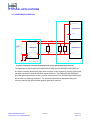
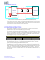
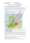
Figure 6 Two-wire conveyor termination and control panel lightning protection
A two wire conveyor control system would be terminated and protected in much the same
way as the three wire conveyor except that the lanyard conductor would not be used and
terminal 8 on the SILBUS-OAS1-BEG would not be used.
5 OPERATING INSTRUCTIONS
The termination unit does not require any operator action to operate once it has been
installed within an IP54 host enclosure and configured correctly.
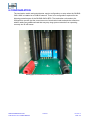
Test connection facilities are provided on the front panel of the termination unit to provide a
method of connecting test equipment to the network while the system is in operation. Care
should be exercised when using these test facilities to not short the SILBUS network and
cause tripping of conveyor drive motors and similar plant.
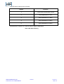
TERMINATION UNIT TEST FACILITY CONNECTIONS
FRONT PANEL NAME
COLOUR
NETWORK SIGNAL
SIG
RED
SIGNAL
COM
BLACK
COMMON
Table 1 Test facility connection details
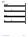
TERMINAL No.
11
14
The test facilities are in the form of two 2mm test sockets spaced at 19mm. These test
sockets will accept standard multimeter probes and leads.
The potentiometer in the OAS1 can be used to match the characteristic impedance of the
cable. The potentiometer can be used to adjust the termination resistance from 100 ohms
to 600 ohms. Turning the potentiometer fully clockwise sets it to 100 ohms. Turning the
potentiometer fully counter clockwise sets it to 600 ohms. Note that the potentiometer is a
multi-turn unit.
SILBUS TERMINATION UNIT
TYPE SILBUS-OAS1 USER'S MANUAL
11 OF 21
120-339-12
Issue: 02