1
INSTRUCTION MANUAL (Ver. 1.1)
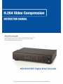
H.264 Video Compression
Digital Video Recorder
About this user guide
Before installing and using this unit, please read this user guide carefully.
Be sure to keep it handy for later reference.
The specifications and information are subject to change without notice for quality improvement.
2
SAFETY PRECAUTIONS
EXPLANATION OF SYMBOLS
This symbol is intended to alert the user to the presence of important
operation and maintenance (servicing) instructions in the literature
accompanying the appliance.
This symbol is intended to alert the user to the presence of
unprotected “dangerous voltage” within the product’s enclosure that
may be strong enough to cause a risk of electric shock persons.
WARNING
To reduce a risk of fire or electric shock, do not expose this product to rain or moisture.
CAUTION
Changes or modifications not expressly approved by the manufacturer may void the user’s authority to
operate this equipment.
CAUTION
Danger of explosion if battery is incorrectly replaced.
Replace only with the same or equivalent type recommended by the manufacturer.
3
The bellow safety precautions must be followed.
WARNING
Do not use if the unit emits smoke, strange sounds is heard, or odor is emitted.
Make sure the power cable is not damaged.
Make sure there is no dust accumulation on the power plug or the outlet.
Disassembly prohibited
Do not place any foreign objects inside the unit.
Do not place a container holding water or other liquids above the unit when it is connected to power.
Do not allow the unit to get wet.
Do not use during thunder/thunder storms.
Do not place in an unstable position.
Do not expose to shock or vibration.
Do not use this unit in areas where it is exposed to the possibility of explosion.
CAUTION
Do not pull on the power cable when removing the power plug from the outlet.
Do not touch the power plug with wet hands.
Do not sit on.
Make sure the cables are connected properly.
Do not place heavy objects on connected units.
Never move this unit while the power is turned on.
Do not block the cooling fans or air ducts.
Do not expose to extreme temperatures or humidity changes.
4
Precautions for supplied AC Adaptor
CAUTION
Never disassemble or modify.
Never get the adaptor wet.
CAUTION
Use only the supplied AC adapter.
Do not connect to other appliances.
Do not connect this unit with the AC adapter in areas reachable to children or where pets move
freely.
Never touch the AC adapter with wet hands.
If the unit emits smoke, strange sounds or smells immediately remove the AC adapter from the outlet.
Do not use during thunder/thunder storms.
CAUTION
Make sure the cable is connected properly.
Preventing damage to a cable
5
Main features
H.264 Video compression
QUADPLEX operation enabling simultaneous recording, playback, networking, and backup.
Instant and convenient data backup & firmware upgrade using USB flash drive
Simple User Interface
Individual channel setting and operation
Motion detection record
Free Dynamic DNS
6
System components and Installation
Requirements for installation and safety
This chapter is for the requirements for safe installation and use.
This kit should be installed on a flat table or in a rack..
The location in which the DVR is installed in the room is very important for proper operation of the system.
When the DVR is installed too closely together or the location is poorly ventilated, the DVR may not operate
properly and maintenance of the DVR may be difficult. Make sure that the air should be sufficiently circulated
within the system operating room and the cover of the main system must be tightly fastened to prevent
malfunction.
There are high voltage parts inside. Do not open the cover during operation.
The DVR must be installed in a place that meets the following environmental conditions.
• Operating temperature: 5°C ~ 40°C (41°F ~ 104°F)
• Operating humidity: 30% ~ 90% RH
• Input voltage: DC +12V 5A
• Power usage: About 25Watts
• Frequency: 60Hz/50Hz
Main replacement parts
• Hard disk (When HDD is factory-installed.): 1 year (25°C environment)
• Cooling fan: 1 year (25°C environment)
• Battery: 2 years (25°C environment)
CAUTION
During the operation of this product, the fluctuation of input voltage must be within 10% of the rated voltage
and the external power outlet must be grounded, otherwise, it may cause electric shock or malfunction of the
product.
Do not connect heat-generating appliances to the same power outlet in which the product is plugged,
otherwise it may cause a fire or malfunction of the product.
The use of an Automatic Voltage Regulator (AVR) is highly recommended to ensure that stable power is
supplied.
7
CAUTION
HDD that is installed in DVR can be changed with a new one. However we guarantee that the new HDD must
be the same brand and model.
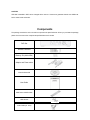
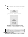
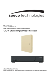
Components
The package contains the main unit and its components as specified below. When you purchase the package,
please check to ensure the components specified below are included.
DVR Set
Remote Controller
Battery1.5V (AAA x 2EA)
Adaptor and Power cable
Client Software CD
User Guide
HDD Power & SATA Cable
HDD Screws
Audio Cable (for 16ch)
8
SPECIFICATIONS
ITEM
Video
Input
Channel, Input Level
Output
Audio
Alarm
8CH
16CH
4CH, Composite
8CH, Composite
16CH, Composite
Signal Format
NTSC/PAL
Video Loss Check
Yes
Main Monitor Output
1 CH BNC, 1CH VGA: Selectable
Signal Format
NTSC/PAL & VGA
Input & Output
4 CH Line input & 1 CH Line output
Audio Codec
G.711(ADPCM)
Sensor Input ((NC/NO Selectable)
Record
4CH
4
4
4
Alarm Output
1 Alarm out by Alarm, Motion, Video Loss
Compression
H.264
Multi-operation
QUADPLEX (Playback/Record/Network/Backup)
352x240
Resolution
352x240
352x240
704x240
704x240
704x480
704x480
704x480
352x288
352x288
352x288
704x288
704x288
704x576
704x576
NTSC
PAL
704x576
Recording quality grade
NETWORK, ECONOMY, NORMAL, HIGH, FINE.
Recording Mode
Continuous / Schedule / Motion/ Sensor/ Manual
Motion Detection
Motion detection setup by Grid
Pre Recording
1 fps for 5 seconds before an event
Post Recording
10 seconds to 3 minutes after an event
Display
Frame Rate ( /Sec)
NTSC: 30fps/ch, 60 fields / PAL: 25fps/ch, 50 fields
Playback
Multi-Decoding
Playback Speed
1, 4
Single channel
× 2, 4, 8
Multi-channels
× 2, 4
Search Mode
Storage
HDD
1, 4, 9
Timeline, Event, Archive, Log
Interface Type
Serial ATA I
9
1, 4, 9, 16
Capacity of 1 HDD
1TB
Internal HDD Number
1
1
File system
Backup
User I/F
1
NaFS
USB Flash drive
Video & Still Image
Network
Video & Still Image
Menu Display
Text UI
Input Method
Front buttons, Remote control
PTZ control & Keyboard DVR control
1 RS-485
Termination
Yes
Dynamic DNS
Yes (Free DDNS)
Network Interface
10/100 base-TX Ethernet (RJ-45)
Client Software (1:1)
Live, Search, Backup, PTZF Camera Control
Web viewer (1:1)
Live, Search, Backup, PTZF Camera Control
Multi-sites Monitoring System (1:n)
Live, Search, Backup, PTZF Camera Control
DLS (Day Light Saving)
Yes
Internal Beep
By Alarm, Motion, Video Loss, HDD error
Multi-Language
Yes
S/W Upgrade
USB Flash drive
Water - mark
Yes (Exclusive viewer)
Power
DC 12V 3A(for 4CH), DC 12V 5A(for 8,16CH)
Weight
Unit Weight (Gross weight)
1.6 Kgs (3.1 Kgs) / 3.5 Lbs (6.8 Lbs)
Dimension
Unit Dimension (W x H x D)
340 mm x 262 mm x 63 mm / 13.4" x 10.3" x 2.5"
Network
Network
Access
Features
Power
source
Compatible HDD Models
COMPANY
MODEL
Seagate
ST31000340SV
Seagate
SIZE
RPM
BUFFER
TYPE
1 TB
7200 RPM
32 MB
Serial ATA
ST3500830SCE
500 GB
7200 RPM
8 MB
Serial ATA
Seagate
ST3250410AS
250 GB
7200 RPM
16 MB
Serial ATA
Seagate
ST3250310SV
250 GB
7200 RPM
8 MB
Serial ATA
Seagate
ST3160815AS
160 GB
7200 RPM
8 MB
Serial ATA
HITACHI
HDS721010KLA330
1 TB
7200 RPM
32 MB
Serial ATA
HITACHI
HDP725050GLA360
500 GB
7200 RPM
16 MB
Serial ATA
10
Western Digital
WD10EACS
1 TB
7200 RPM
16 MB
Serial ATA
Western Digital
WD5000AACS
500 GB
7200 RPM
16 MB
Serial ATA
Western Digital
WD2500AAKS
250 GB
7200 RPM
16 MB
Serial ATA
INDEX
1. NAME & FUNCTION ..................................................................................................... 13
1-1. Front panel ................................................................................................................ 13
1-2. Remote controller ..................................................................................................... 14
1-3. Rear panel and connection ...................................................................................... 15
2. PREPARATION ............................................................................................................. 19
2-1. Selecting the type of monitor (TV monitor and VGA monitor) .............................. 19
2-2. Live screen ................................................................................................................ 20
2-3. Time setting............................................................................................................... 21
2-4. DLS (Day Light Saving) time setting ....................................................................... 22
3. OPERATION - RECORD ............................................................................................... 24
3-1. CONTINUOUS recording .......................................................................................... 25
3-2. MOTION DETECTION recording .............................................................................. 25
3-3. SENSOR recording ................................................................................................... 28
3-4. Manual recording ...................................................................................................... 29
3-5. SCHEDULE recording .............................................................................................. 30
4. OPERATION - PLAYBACK ........................................................................................... 32
4-1. EVENT SEARCH........................................................................................................ 33
11
4-2. TIMELINE SEARCH ................................................................................................... 34
4-3. GO TO SPECIFIC TIME ............................................................................................. 35
4-4. GO TO THE FIRST VIDEO......................................................................................... 36
4-5. GO TO THE LAST VIDEO.......................................................................................... 36
4-6. SYSTEM LOG ............................................................................................................ 36
4-7. ARCHIVE.................................................................................................................... 37
5. OPERATION - BACKUP TO USB FLASH DRIVE ........................................................ 38
5-1. Archiving and backup JPEG in Live mode ............................................................. 39
5-2. Archiving and backup VIDEO in Playback mode ................................................... 40
5-3. Backup JPEG, AVI, or EXCLUSIVE VIDEO from ARCHIVE search ........................ 41
5-4. Playback of AVI or EXCLUSIVE VIDEO ................................................................... 43
6. SETUP ........................................................................................................................... 44
6-1. LIVE............................................................................................................................ 44
6-2. RECORD .................................................................................................................... 46
6-3. DEVICE ...................................................................................................................... 47
6-4. NETWORK ................................................................................................................. 50
6-5. STORAGE .................................................................................................................. 53
6-6. SYSTEM ..................................................................................................................... 54
7. NETWORK ACCESS USING THE EXCLUSIVE NETWORK VIEWER ........................ 57
7-1. PC requirements ....................................................................................................... 57
7-2. Installing the network viewer ................................................................................... 58
7-3. Live monitoring mode and functions. ..................................................................... 59
7-4. Bi directional audio .................................................................................................. 61
12
7-5. Remote search mode and functions ....................................................................... 61
7-6. PC System configuration ......................................................................................... 64
8. NETWORK – BY AN WEB-BROWSER VIEWER ......................................................... 68
APPENDIX: HOW TO CONNECT NETWORK.................................................................. 70
A. How to set IP address of the DVR and open TCP port of the router?......................... 70
B. How to access DVR from Remote PC? ...................................................................... 72
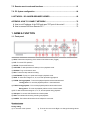
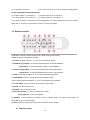
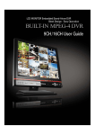
1. NAME & FUNCTION
1-1. Front panel
① SEQ: To start auto sequencing of the screen in full screen mode. (Toggle)
② PTZ: To control PTZ operation
③ SETUP: To launch SETUP menu.
④ CAPTURE: To start operations of backup in live or playback mode.
⑤ SEARCH: To go to the search menu.
⑥ REC: To start and stop manual recording.
⑦ PLAY/PAUSE: To play or to pause the footage in playback mode.
⑧ REW: To rewind the footage at 1x, 2x, 4x, and 8x speed during playback.
⑨ F/REW : During playback - To move the playback position 60 seconds backward.
During pause - To move the playback position 1 frame backward.
⑩ F/ADV: During playback - To move the playback position 60 seconds forward.
During pause - To move the playback position moves 1 frame forward.
⑪ FF: To fast forward the footage at 1x, 2x, 4x, and 8x speeds during playback.
⑫ USB port: To connect USB Thumb drive to backup data.
⑬ HDD: The indicator blinks during recording and playback.
⑭ POWER: The indicator blinks when the AC adaptor is connected.
Direction button
During setting
ⓐ To move the cursor Upward.
ⓑ To move the cursor to the Right or to change the setting values.
13
ⓒ To move the cursor Down.
ⓓ To move the cursor to the Left or to change the setting values.
During Live/playback & Entering password
ⓐ To select camera 1 or To enter No. 1
ⓑ To select camera 2 or To enter No. 2.
ⓒ To select camera 3 or To enter No. 3.
ⓓ To select camera 4 or To enter No. 4.
ⓔ To select full screen or quad screen view in live/playback or To select desired menu item or to store the
setup value.ⓕ To return to previous menu screen or To exit from playback.
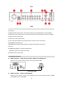
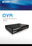
1-2. Remote controller
① ID: When a remote control ID number is set in DVR, press it before number.
② REC: To start and stop manual recording.
③ Number: To select channel (1, 2, 3, & 4) or to enter DVR ID number.
④ F/REW: During playback - To move the playback position 60 seconds backward.
During pause - To move the playback position 1 frame backward.
⑤ F/ADV: During playback - To move the playback position 60 seconds forward.
During pause - To move the playback position moves 1 frame forward.
⑥ REW: To rewind the footage at 1x, 2x, 4x, and 8x speed during playback.
⑦ PLAY/PAUSE: To play or to pause the footage in playback mode.
⑧ FF: To fast forward the footage at 1x, 2x, 4x, and 8x speeds during playback.
⑨ Control button: Press to move the menu items or select channel.
⑩ SETUP: To launch SETUP menu.
⑪ SEARCH: To go to the search menu.
⑫ ESC: During setting - To return to previous menu screen.
During playback - To exit from playback.
⑬ BACKUP: To start operations of backup in live or playback mode. (The same function button as
CAPTURE on the front panel of DVR.)
⑭ SEQ: To start auto sequencing of the screen in full screen mode. (Toggle)
Operation range
14
30° 30°
5m
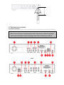
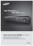
1-3. Rear panel and connection
1-3-1. Basic connections
Do not power this system on before all the connections are completed.
Make sure all the connections are properly. Faulty connection may result in the system being damaged.
The DC plug of the AC adaptor is easy to be unplugged. Please make sure that the plug is removed.
4CH
15
8CH
16CH
① Cooling fan
② AUDIO IN: Audio input terminal (* Use the audio cable which is provided with the 16ch dvr package)
③ AUDIO OUT: Audio output terminal (* Use the audio cable which is provided with the 16ch dvr package)
④ VIDEO IN: Video input terminal
⑤ VIDEO OUT: Video output terminal
⑥ VGA: VGA (Video Graphics Array) output terminal. Connects to the PC VGA monitor.
⑦ ETHERNET: Network terminal
⑧ SENSOR IN & ALARM OUT: External sensor terminal & External alarm out terminal
⑨ RS-485
⑩ TERMINATION ON/OFF: Termination ON/OF switch
CVBS/VGA: System video output format switch
⑫ POWER: DC12V input terminal
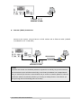
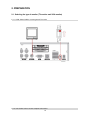
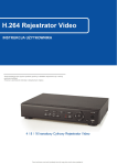
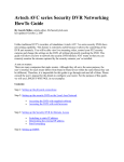
1-3-2. Network connections
LAN Connection – Using the cross cable, without a switching hub
Connect to the system directly, using a cross type network cable
Cross type cable
LAN Connection – Using a switching hub
Connect to the system, using a hub (Switching hub) and an Ethernet cable (10BASET/100BASE-TX CAT 5 LAN cable)
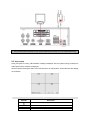
16
IP Router or HUB
Internet (ADSL) Connection
Connect to the system, using an Router or ADSL modem and an Ethernet cable (10BASET/100BASE-TX CAT 5 LAN cable)
ADSL Modem
Internet
IP Router or HUB
NOTICE
If you have a IP line with one IP address (whether it is dynamic IP or fixed IP), but you have more than
one internet device (such as PC/PCs and a DVR); to use Router (It is different from a simple Network
Hub); you must set up the Router to work with DVR; and you must use a network capable PC within the
local Router network to do the setup. Whether you are using an existing Router or a new Router, you
must go through the Port Forwarding portion of the setup.
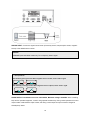
1-3-3. Sensor and alarm connections
17
SENSOR INPUT: Connect two signal lines of sensor (infrared ray sensor, heat perception sensor, magnetic
sensor) to the desired sensor number.
NOTICE
SENSOR inputs need dried contact only. Do not input any electric signal.
---: Not operational
N/O: Normally open type sensor. When magnetic sensor is closed, sensor sends a signal.
N/C: Normally closed type sensor. When magnetic sensor is opened, sensor sends a signal.
ALARM OUTPUT: Use Maximum current: 0.5A/125VAC, Maximum voltage: 1A/30VDC. When controlling
lamp and AC operated equipment, control it using separate outside relay. During normal operation the control
output contact is maintained at “Open” status, and during control output the output contact is changed to
Closed(short)” status.
18
2. PREPARATION
2-1. Selecting the type of monitor (TV monitor and VGA monitor)
2-1-1. CVBS: Select CVBS to connect general TV monitor
2-1-2. VGA: Select VGA to connect computer VGA monitor
19
The general TV monitor terminal and the computer VGA monitor terminal can not be used simultaneously.
2-2. Live screen
During the system is booting, “INITIALIZING” message is displayed. After the system booting is finished, the
video inputs from the cameras are displayed.
Various indicators showing the status of the DVR are shown as OSD symbols. These OSD and video display
can be hidden.
Indicator
C
R
S
Description
Continuous recording in progress
Manual recording in progress
Sensor alarm recording in progress
20
M
Motion alarm recording in progress
Indicates that audio/audios is/are mute, single, or mixed.
Indicates that alarm is detected
Indicates that motion is detected
Indicates that a network client is connected to the DVR.
Indicates that sequencing mode is enabled.
R:A,0..
Indicates that remote controller ID is set.
Indicates the HDD is being recycled
If camera is not connected or the connector is not properly connected to video input terminal, “NO
VIDEO” is displayed on the monitor.
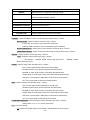
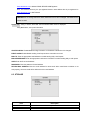
2-3. Time setting
1. Press the SETUP button. Press Up arrow button four times to enter “1111” (Default password) and press
the SEL button. Then the SETUP screen is displayed. The password change is highly recommended to
avoid any unauthorized usage.
2. Press the direction button to select the SYSTEM menu and press the SEL button.
3. Go to DATE FORMAT field using ▲▼ button and select the date format using ▶◀ button.
4. Go
YYYY/MM/DD (Ex. 2008/5/6)
YYYY-MM-DD (Ex. 2008-05-06)
MM/DD/YYYY
MM-DD-YYYY
DD/MM/YYYY
to DATE &
21
DD-MM-YYYY
TIME field using ▲▼ button and press the SEL button.
5. Select the date and time that is to be changed using
▶◀
button, change a value using ▲▼ button, and
press the SEL button. Then UPDATE DATE & TIME screen is displayed.
6. Select CONFIRM and press the SEL button. Then the system will reboot automatically showing
“INITIALIZING…” message.
Setting in TIME MISMATCH
When the time of DVR is set earlier than the time of the last video data on HDD, the following message is
displayed.
Selecting “YES”: the video data between “SYSTEM TIME” and “HDD LAST TIME” will be deleted.
Selecting “GO TO TEST MODE”: Select only the video data between “SYSTEM TIME” and “HDD
LAST TIME” must not be deleted. Otherwise, do not select “GO TO TEST MODE”.
2-4. DLS (Day Light Saving) time setting
EU Territory – When your time zone belongs to EU territory
1. Go to SYSTEM>DLS field using ▲▼ button and select EU using ▶◀ button.
2. Go to GMT AREA field using ▲▼ button and select GMT time of your country from +00:00 to +05:00.
22
USA Territory – When your time zone belongs to USA territory
1. Go to SYSTEM>DLS field using ▲▼button and select USA using ▶◀ button.
Other Territory – When your time zone does not belong to USA and EU territory
1. Go to SYSTEM>DLS field using ▲▼ button and select ETC using
▶◀
button. Then the summer time
setup fields are displayed.
2. Select BEGIN field using ▲▼ button and press the SEL button. Then DAYLIGHT SAVING BEGIN
screen is displayed.
3. Select the date and time that is changed using
press the SEL button.
23
▶◀
button, change a value using ▲▼ button, and
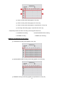
4. After exit from DAYLIGHT SAVING BEGIN field setting, select DAYLIGHT SAVING END field using
▲▼ button and press the SEL button. Then DLS BEGIN screen is displayed.
5. Select the date and time that is changed using
▶◀
button, change a value using ▲▼ button, and
press the SEL button.
3. OPERATION - RECORD
The system has 6 recoding modes.
CONTINUOUS recording – Recording continuously when the DVR is turned on.
C icon is displayed on the screen. (Refer to page 23)
MOTION DETECTION recording – Recording when the DVR detects motion form input video.
M icon is displayed on the screen. (Refer to page 23)
SENSOR recording – Recording when the external sensor of DVR is set off.
S icon is displayed on the screen. (Refer to page 25)
SCHEDULE recording – Recording according to the schedule setting. (Refer to page 27)
None – No recording
Manual recording by REC button – Recording when the REC button of DVR is pressed.
R icon is displayed on the screen. (Refer to page 27)
24
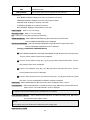
3-1. CONTINUOUS recording
CONTINUOUS recoding setting is available for each channel. The DVR records automatically input video in
CONTINUOUS recording mode as a factory default, unless RECODING mode is changed.
① Set the basic record menu using ▲▼ ▶◀ buttons before setting Motion detection.
RESOLUTION
CHANNEL
FRAME RATE
QUALITY
Upon connecting cameras, the DVR records input video displaying C on the screen.
② To stop CONTINUOUS recording, go to RECORDING BY filed using ▲▼button and select NONE using
▶◀button.
③ Repeat this step to set the other channel as necessary.
④ Press ESC button to go to SAVE SETUP and save the
.
3-2. MOTION DETECTION recording
A motion detection setting is available for each channel.
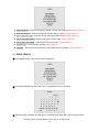
① Set the basic record menu using the direction buttons before setting Motion detection.
RESOLUTION
25
CHANNEL:
FRAME RATE
QUALITY
Upon Motion detection, the DVR records input video with these setting.
② To select a channel for motion detection recording, go to CHANNEL filed using ▲▼ button and select a
channel from CH1, CH2, CH3, and CH4 using ▶◀ button.
③ Go to RECORDING BY filed using ▲▼button and select MOTION using ▶◀button.
④ Go to DEVICE>CHANNEL>MOTION ZONE filed using ▲▼button and select PARTIAL ZONE using
▶◀button.
When FULL ZONE is selected, the DVR detects a motion from whole video screen. Set only MOTION
SENSITIVITY.
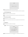
⑤ Select the grids for motion detection using ▲▼▶◀button and SEL button. Then the selected grids are
displayed in Pink color.
⑥ Go to MOTION SENSITIVITY using ▲▼ button and select the sensitivity using ▶◀button.
26
Sensitivity grade: 9 –The highest sensitivity against motion / 1 – The lowest sensitivity against motion
⑦ Go to PRE RECORD using ▲▼ button and select ON or OFF as necessary using ▶◀button.
When PRE RECORD is ON, the DVR records 1 fps for 5 seconds before any motion detection.
⑧ Go to POST RECORD using ▲▼ button and select the time as necessary using ▶◀button.
The available POST RECORD time: 5 to 60 seconds.
⑨ Repeat this step to set the other channel as necessary.
⑩Press ESC button to go to SAVE SETUP and save the setting
27
3-3. SENSOR recording
Sensor is connected to each channel and be used a recording trigger.
① Connect a sensor to a sensor terminal on the rear of the DVR. (Refer to page 16)
② Set the basic record menu using ▲▼ ▶◀ buttons before setting Sensor recording.
RESOLUTION
CHANNEL
FRAME RATE
QUALITY
Upon sensor sends a signal to the DVR, the DVR records input video displaying S on the screen.
③ To select a channel for sensor triggered recording, go to CHANNEL filed using ▲▼ button and select a
channel from CH1, CH2, CH3, and CH4 using ▶◀ button.
④ Go to RECORDING BY filed using ▲▼button and select SENSOR using ▶◀button.
⑤ Go to DEVICE>CHANNEL>SENSOR RECORDING using ▲▼ button and select the number of sensor
that is linked with the video channel using ▶◀button.
⑥ Go to PRE RECORD using ▲▼ button and select ON or OFF as necessary using ▶◀button.
⑦ Go to POST RECORD using ▲▼ button and select the time as necessary using ▶◀button.
28
Repeat this step to set the other channel as necessary.
Press ESC button to go to SAVE SETUP and save the setting.
Alarm setting on activation of event such as motion, sensor, video loss, & HDD fail
When an event is activated, a relay signal triggers the external alarm device.
ⓐ Connect an external alarm device to the alarm out terminal (Refer to page 16)
ⓑ Go to DEVICE>ALARM filed using ▲▼button and select OFF, SENSOR, MOTION, VIDEO LOSS, HDD
FAIL, or ALL as necessary using
button.
ⓒ Go to ALARM/BEEP DURATION using ▲▼ button and select alarm/beep duration as necessary using
button.
ⓓ Press ESC button to go to SAVE SETUP and save the setting.
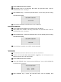
3-4. Manual recording
To start manual recording, press REC button. Then, “R” is displayed on the screen and the DVR starts
recording of every channels.
To stop manual recording, press REC button. Then, “R” disappears on the screen and the DVR stops
recording of every channel.
29
3-5. SCHEDULE recording
① Set the basic record menu using ▲▼ ▶◀ buttons before setting Schedule.
RESOLUTION
CHANNEL
FRAME RATE
QUALITY
Upon connecting cameras, the DVR records input video using schedule setting.
② Before setting schedule, set the followings as necessary
MOTION ZONE
MOTION SENSITIVITY
SENSOR TYPE
PRE RECORD
POST EVENT RECORD
③ Go to RECORDING BY filed using ▲▼button and select SCHEDULE using ▶◀button.
Go to SCHEDULE using ▲▼ button and press SEL button. Then SCHEDULE setting screen is displayed.
(When the channel 1 is selected from CHANNEL field, “SCHEDULE – CH1” is displayed.)
Move the cursor to one of following fields and set a different mode using SEL button.
30
ⓐ: Same recording mode setting apply to every day.
ⓑ: Same recording mode setting apply to the whole day.
ⓒ: Same recording mode setting apply to a specified time of every day.
ⓓ: Recording mode setting apply to a specified time of the day.
Repeat the procedure to select a recording mode using SEL button from;
C: CONTINOUS recording
M: MOTION DETECTION recording
S: SENSOR recording
- : DISABLE (No recording)
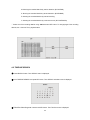
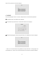
EXAMPLE of SCHEDULE recording setting
ⓐ: CONTINOUS recording mode applies to every day.
ⓑ: MOTION DETECTION recording mode setting applies to the whole day.
ⓒ: SENSOR recording mode setting applies to a specified time of every day.
31
EXAMPLE of copying the CH1 SCHEDULE recording setting to CH2
⑴ Set the CH1 SCHEDULE and return RECORD menu using ESC button.
⑵ Go to CHANNEL field and select CH2 using ▲▼
▶◀
buttons. And go to SCHEDULE field and press SEL
button. Then SCHEDULE – CH2 screen is displayed.
⑶ Move the cursor to COPY FROM using ▲▼ buttons and select CH1 using
button. Then the CH1 SCHEDULE recording setting is copied to CH2.
4. OPERATION - PLAYBACK
The system has 7 methods of searching a recorded video.
32
▶◀
buttons. Finally press SEL
EVENT SEARCH – Searching through the calendar, channel, and recoding mode. (Refer to page 30)
TIMELINE SEARCH – Searching through the calendar and the timeline. (Refer to page 31)
GO TO SPECIFIC TIME – Searching through selecting the date and time. (Refer to page 32)
GO TO THE FIRST VIDEO – Searching the oldest recorded video. (Refer to page 32)
GO TO THE LAST VIDEO – Searching the last recorded video. (Refer to page 33)
SYSTEM LOG – View the system log data. (Refer to page 33)
ARCHIVE – Searching the archived JPEG or video data through the calendar. (Refer to page 34)
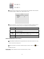
4-1. EVENT SEARCH
① Press SEARCH button. Then SEARCH menu is displayed.
② Go to EVENT SEARCH and press SEL button. Then SEARCH screen is displayed.
③ Select the date, a channel, and the type of recording mode using ▲▼▶◀ buttons and SEL button.
A: Showing all the recorded data list of every type of recording mode
33
M: Showing the recorded data list by motion detection. (BY MOTION)
S: Showing the recorded data list by sensor detection. (BY SENSOR)
R: Showing the recorded data list by manual recording.
C: Showing the recorded data list by continuous record. (BY CONTINOUS)
Select one of the recording data list using ▲▼buttons and SEL button. To change pages of the recording
data list, use ▶◀ buttons. Then, playback starts.
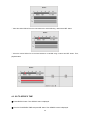
4-2. TIMELINE SEARCH
① Press SEARCH button. Then SEARCH menu is displayed.
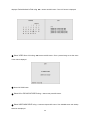
② Go to TIMELINE SEARCH and press SEL button. Then SEARCH calendar screen is displayed.
③ Select the date using ▲▼▶◀ buttons and SEL button. Then Timeline screen is displayed.
34
Move the vertical Yellow line to the time between 0 to 24 HOUR using ▶◀buttons and SEL button.
Move the vertical Yellow line to the time between 0 to 60 MIN using
▶◀buttons
and SEL button. Then,
playback starts.
4-3. GO TO SPECIFIC TIME
① Press SEARCH button. Then SEARCH menu is displayed.
② Go to GO TO SPECIFIC TIME and press SEL button. Then SEARCH screen is displayed.
35
③ Select the date and time using ▲▼▶◀ buttons and press SEL button.
Then, playback starts. When there is no recorded data, the closest data to the selected time is played back.
4-4. GO TO THE FIRST VIDEO
① Press SEARCH button. Then SEARCH menu is displayed.
② Go to GO TO THE FIRST VIDEO and press SEL button. Then, playback of the oldest recorded video data
starts.
4-5. GO TO THE LAST VIDEO
① Press SEARCH button. Then SEARCH menu is displayed.
② Go to GO TO THE LAST VIDEO and press SEL button. Then, playback of the last recorded video data
starts.
4-6. SYSTEM LOG
① Press SEARCH button. Then SEARCH menu is displayed.
② Go to SYSTEM LOG and press SEL button. Then SYSTEM LOG calendar screen is displayed.
③ Select the date using ▲▼▶◀ buttons and press SEL button. To change pages of the log data list, use ▶◀
36
buttons. Then, log list screen of the date is displayed.
4-7. ARCHIVE
The archived still-images or video in Live screen or Playback screen can be searched and played back.
① Press SEARCH button. Then SEARCH menu is displayed.
② Go to ARCHIVE and press SEL button. Then ARCHIVE calendar screen is displayed.
③ Select the date using ▲▼▶◀ buttons and press SEL button. Then ARCHIVE LIST screen is displayed.
Select one of the archived data list using ▲▼buttons and press SEL button. To change pages of the
archived data list, use ▶◀ buttons. Then, the archived still-image or the first frame of video data is displayed.
37
5. OPERATION - BACKUP TO USB FLASH DRIVE
JPEG and video can be backed up to USB flash drive.
When USB flash drive cannot be recognized, format USB flash drive as FAT format on PC.
Archiving and backup JPEG in Live mode – JPEG image can be archived on HDD and be backed up to
USB flash drive in live mode. (Refer to page 35)
Archiving and backup VIDEO in Playback mode – JPEG, AVI, or EXCLUSIVE VIDEO can be archived
on HDD and be backed up to USB flash drive in playback mode. (Refer to page 36)
Backup JPEG, AVI, or EXCLUSIVE VIDEO from ARCHIVE search – JPEG, AVI, or EXCLUSIVE VIDEO
can be backed up from ARCHIVE search menu. (Refer to page 37)
Playback of AVI or EXCLUSIVE VIDEO – AVI can be played back using Media Player software.
EXCLUSIVE VIDEO can be played back using the exclusive viewer. (Refer to page 39)
When the selected list is video, VIDEO TYPE screen is displayed.
AVI: When AVI is selected, the video is backed up as AVI format.
EXCLUSIVE VIDEO: When this is selected, the video is backed up as an exclusive video format
that can be played back using the exclusive viewer.
38
5-1. Archiving and backup JPEG in Live mode
① Connect a USB flash drive to the USB terminal.
② Press CAPTURE button at the scene to be backed up. “JPEG IMAGE IS ARCHIVED ON HDD” is
displayed.
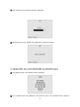
③ Then SAVING screen with backup status bar is displayed after “CHECKING USB” message.
After the backup is done, “BACKUP IS COMPLETED” message is displayed.
⑤ When the DVR can not recognize USB thumb drive or no USB thumb drive is connected to the USB
terminal, “PLEASE CHECK BACKUP DEVICE” message is displayed.
39
5-2. Archiving and backup VIDEO in Playback mode
① Connect a USB flash drive to the USB terminal.
② Press SEARCH button and go to the video to be backed up.
③ Press CAPTURE button at the scene of video to be backed up. Then SELECT BACKUP FILE TYPE
screen is displayed. Select a file type from JPEG, AVI, or EXCLUSIVE VIDEO using
▶◀
buttons and
press SEL button. Then DURATION screen is displayed.
When JPEG IMAGE is selected, please take the same backup procedure as 5-1. ③
⑤ Set the duration to be archived and backed up from the scene of video using ▲▼ buttons and press
SEL button.
40
⑥ Then SAVING screen with backup status bar is displayed
⑦ After the backup is done, “BACKUP IS COMPLETED” message is displayed.
5-3. Backup JPEG, AVI, or EXCLUSIVE VIDEO from ARCHIVE search
① Press SEARCH button. Then SEARCH screen is displayed.
② Go to ARCHIVE field using ▲▼buttons and press SEL button. Then ARCHIVE search calendar is
41
displayed. Select the date in Red using ▲▼▶◀ buttons and SEL button. Then LIST screen is displayed.
③ Select VIDEO from a list using ▲▼ buttons and SEL button. Then a paused image or the first scene
of the video is displayed.
④ Press CAPTURE button.
⑤ Select AVI or EXCLUSIVE VIDEO using ▶◀ buttons and press SEL button.
⑥ Select USB FLASH DRIVE using ▶◀ buttons and press SEL button. Then SAVING screen with backup
status bar is displayed.
42
⑦ After the backup is done, “BACKUP IS COMPLETED” message is displayed.
5-4. Playback of AVI or EXCLUSIVE VIDEO
Playback of AVI format: AVI format video can be played back by Window Media Player™ or other
media player that is compatible with AVI format video.
When PC doesn’t have proper H.264 CODEC, the media players can not playback the AVI
format video. Then install CODEC that is provided on the CD-ROM.
DVR (Exclusive video format): DVR format video can be played back by the player (the exclusive
viewer) that the DVR copies on USB thumb drive with video.
Three files are copied on USB thumb drive
- DVR file: Exclusive format video file.
- SMI file: Title file of date and time.
- PLAYER: Exclusive video viewer.
43
6. SETUP
Press the SETUP button, then the password window is displayed. The default password is 1111, which can
be entered by pressing the up button 4 times and then pressing the SEL button. After input password, the
SETUP screen is displayed.
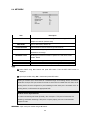
6-1. LIVE
Item
OSD
SEQUENCE
Description
Enable/disable OSD (on-screen-display).
Enable/disable sequential display of video channels in full screen mode.
44
SEQ-DWELL TIME
Dwell time for each cannel display in sequential display mode.
OSD CONTRAST
Set the visibility level of the On Screen Display (OSD)
CHANNEL
Select the channel for applying the following settings.
DISPLAY
SEQUENCE LIST
BRIGHTNESS
CONTRAST
HUE
SATURATION
Enable/disable display of the video channel in live display mode
Enable/disable the specified channel to be included in sequential list.
Change the brightness value for the specified channel
Change the contrast value for the specified channel
Change the hue value for the specified channel
Change the saturation value for the specified channel
OSD – Select ON/OFF using ▶◀ buttons.
ON: OSD (on-screen-display) such as the time, date, the channel, and the characters and symbols
are displayed on the screen.
OFF: OSD (on-screen-display) is NOT displayed, except recording indicator icons.
SEQUENCE – Select ON/OFF using ▶◀ buttons.
ON: Channel in full screen mode is rotated.
OFF: Channel on a single live screen is NOT rotated.
SEQ-DWELL TIME – Select channel sequence interval time using ▶◀ buttons.
Setting values: 1, 2, 3, 4, ~ 56, 57, 58, 60 seconds.
OSD CONTRAST – Set the contrast of OSD on the screen using ▶◀ buttons.
Setting values of the display bar: 20% (the most transparent) ~ 100%
Renaming of CHANNEL
① Select CHANNEL using ▶◀ buttons and press SEL button. Then the CAMERA TITLE screen is
displayed.
② Input characters using ▲▼▶◀ buttons.
Available characters list:
ABC DE FGH IJKLM NOPQ RSTUV WXYZ
[ \ ]^_‘abcdefghijklmnopqrstuvwxyz
{|}!“#$%&’( )*+, -./ 0123456789:;<>?@
Setting of CHANNEL - Select CHANNEL to set the video setting as bellows using ▶◀ buttons
DISPLAY – Select ON/OFF using ▶◀ buttons.
ON: The live screen of the channel is displayed.
OFF: The live screen of the channel is NOT displayed.
SEQUENCE LIST – Select ON/OFF using ▶◀ buttons.
45
ON: The channel is included in sequencing channels.
OFF: The channel is NOT included in sequence list.
BNRIGHTNESS – Set the brightness of the channel using ▶◀ buttons.
Setting values of the display bar: 0% ~ 100% (The most brightness)
CONTRAST – Set the contrast of the channel using ▶◀ buttons.
Setting values of the display bar: 0% ~ 100% (The most contrast)
HUE – Set the hue of the channel using ▶◀ buttons.
Setting values of the display bar: 0% ~ 100%
SATURATION – Set the saturation of the channel using ▶◀ buttons.
Setting values of the display bar: 0% ~ 100%
6-2. RECORD
Menu item
RESOLUTION
Description
Set resolution to either
704x480(NTSC)/704X576(PAL) or 352x240(NTSC)/352X288(PAL).
CHANNEL
Select the channel for applying the following settings.
Set the frame rate for the specified channel.
FRAME RATE
The sum of the frame rate values from each channel cannot exceed maximum
frame rates for a particular recording resolution.
The maximum frame rate: 120/100fps - 352x240(NTSC)/352X288(PAL)
30/25 fps - 704x480(NTSC)/704X576(PAL)
QUALITY
Select the recording quality for the specified channel from NETWORK,
ECONOMY, NORMAL, HIGH, FINE.
RECORDING BY
Assign
the
recording
mode
for
each
channel.
Recording
modes:
CONTINOUS, MOTION, SENSOR, SCHEDULE, and NONE.
PRE RECORD
Enable/disable pre-event recording. Pre-event recording time is 5 sec and
only intra-frames are recorded for pre-event recording.
POST RECORD
AUDIO
SCHEDULE
Set post event recording time duration for the specified channel
Enable/disable audio for the specified channel
Set recording schedule.
RESOLUTION – Select the resolution for the recording using ▶◀ buttons.
352x240: The input video is recorded as 352x240 resolution.
46
704x240: The input video is recorded as 704x240 resolution on 8 & 16ch dvr.
704x480: The input video is recorded as 704x480 resolution.
The resolution setting is applied to every channel.
Setting of CHANNEL - Select CHANNEL to set the recording setting as bellows using ▶◀ buttons
FRAME RATE – Set the frame rate value using ▶◀ buttons.
The total frame rate when resolution is 704X480(NTSC) / 704X576(PAL): 30 / 25
The total frame rate when resolution is 352X240 (NTSC) / 352X288(PAL): 120 / 100
QUALITY – Select the quality of the recording video using ▶◀ buttons.
Setting values: FINE, HIGH, NORMAL, ECONOMY, NETWORK (default : HIGH)
RECORDING BY – Select the recording mode using ▶◀ buttons.
CONTINOUS: The input video is recorded when the DVR is turned ON.
MOTION: The input video is recorded when the motion is detected.
SENSOR: The input video is recorded when the external sensor is activated.
SCHEDULE: The input video is recorded according to SCHEDULE setting.
NONE: The input video is NOT recorded.
PRE RECORD – Select ON/OFF of the pre-recording on the event using ▶◀ buttons.
ON: The 1ips of video for 5 seconds is recorded before the event (motion detection or
sensor activation).
OFF: No pre-recording.
POST RECORD – Set the recording time after the event using ▶◀ buttons.
Setting values: 5 ~ 30 seconds
AUDIO – Select ON/OFF of the audio recording using ▶◀ buttons.
ON: The audio is recorded.
OFF: The audio is NOT recorded.
SCHEDULE – Set the recoding schedule of each channel.
6-3. DEVICE
Item
CHANNEL
Description
Select the channel for applying the following settings.
MOTION ZONE
Select Full Zone or Partial Zone for motion sensing.
MOTION SENSITIVITY
Set the motion sensitivity for the specified channel.
47
SENSOR RECORDING
SENSOR
TYPE
Select the channel to link with sensor.
Select the sensor for applying the following settings.
Set the type of sensor for the specified channel from none,
NOEMAL OPEN & NORMAL CLOSE
ALARM
Select from OFF, SENSOR, MOTION, VIDEO LOSS, HDD FAIL, & ALL..
BEEP
Select from OFF, SENSOR, MOTION, VIDEO LOSS, HDD FAIL, & ALL...
ALARM/BEEP DURATION
PTZ
REMOTE CONTROLLER ID
BUTTON TONE
Set alarm and beep duration
PTZ control setting
Select the ID of remote controller.
Enable / Disable the sound tone of front buttons.
CHANNEL - Select CHANNEL to set the recording setting as bellows using ▶◀ buttons
MOTION ZONE – Select the motion zone type using ▶◀ buttons.
FULL ZONE: The motion on the whole screen is detected.
PARTIAL ZONE: The motion on the pre-set detection grid is detected.
MOTION SENSITIVITY – Set the level of motion detection sensitivity using ▶◀ buttons.
SENSOR RECORDING – Select the sensor to link with the recording channel using ▶◀ buttons..
SENSOR - Select a sensor to set the type using ▶◀ buttons
TYPE – Select the external sensor type using ▶◀ buttons.
---: No operation
NOEMAL OPEN: Normal open type sensor
NORMAL CLOSE:
Normal close type sensor
ALARM - Select an event to link with alarm using ▶◀ buttons.
OFF: An event signal is NOT linked with the external alarm.
SENSOR: A sensor event signal is linked with the external alarm.
MOTION: An event signal of sensor is linked with the external alarm.
VIDEO LOSS: An event signal of video loss is linked with the external alarm.
HDD FAIL: An event signal of HDD failure is linked with the external alarm.
ALL: Every event signal is linked with the external alarm.
BEEP - Select an event to link with beep using ▶◀ buttons.
OFF: An event signal is NOT linked with the internal beep.
SENSOR: A sensor event signal is linked with the internal beep.
MOTION: An event signal of sensor is linked with the internal beep.
VIDEO LOSS: An event signal of video loss is linked with the internal beep.
HDD FAIL: An event signal of HDD failure is linked with the internal beep.
ALL: Every event signal is linked with the internal beep.
ALARM/BEEP DURATION - Select the length of alarm and beep output using ▶◀ buttons.
Setting values: 5 / 6 / 7 ~ 57 / 58 / 59 / 60 seconds
PTZ - PTZ control setting
① Connect the RS-485 cables of PTZ camera to the RS-485 port on the rear panel.
48
② Press SEL button to enter the menu. Then PTZ menu screen is displayed. Select the Specific
CAMERA CHANNEL, CAMERA TYPE, CAMERA SPEED, and ID .
③ Press the PTZ button on the front panel. The control screen will appear. Highlight the item to
select and control the cameras by using the UP and DOWN or LEFT and RIGHT buttons.
Item
Description
PAN / TILT
Use the UP or DOWN button for TILT and LEFT or RIGHT button for PAN
of the selected camera.
ZOOM /
Use the UP or DOWN button for ZOOM in or out and LEFT or RIGHT
FOCUS
button for FOCUS near or far of the selected camera.
INITIALIZE
Initialize the PTZ settings of the selected camera.
REMOTE CONTROLLER ID (Example: Number 3)
① Select REMOTE CONTROLLER ID using ▲▼ buttons and select the ID number from 3 using
▶◀
buttons. And exit from the setup menu.
② Press the ID button on the remote controller and press a number 3 button. Then
displayed on the screen.
BUTTON TONE - Enable / Disable the sound tone of front buttons using ▶◀ buttons.
49
icon is
6-4. NETWORK
Item
Description
PORT
Individual port for network streaming when connecting the DVR to a
multiple unit network. (Default: 5445)
WEB PORT
CLIENT ACCESS
BANDWIDTH SAVING
Port for Web Viewer, default : 80
Enable/Disable remote access through client software.
Enable/Disable only key frame transmission when the network
bandwidth is not enough.
NETWORK TYPE
Set the type of network connection. Options are: LAN, DHCP, ADSL
Default : DHCP
DDNS
SEND E-MAIL
Enable/disable using domain name address through DDNS server.
Send an e-mail notification with captured image when event happened.
PORT
① Select PORT using ▲▼ buttons and press SEL button. Then the SET PORT screen is
displayed.
② Input a port number using ▲▼▶◀ buttons and press SEL button.
When you connect one or more DVRs to a network through an IP sharing device, each device
must have a unique TCP port number for access to each unit from outside the LAN. Also, the IP
sharing device must be configured for port forwarding so when each port is accessed on the IP
sharing device, it will forward to the appropriate DVR.
Network access beyond Router
In order to access beyond Router (Firewall), user must open 1 TCP port for Command, Live
steaming, and Search streaming. If this port is not open properly, user can not access DVR
beyond a router.
WEB PORT - Input a web port number using ▲▼ buttons.
50
CLIENT ACCESS – Select ON/OFF using ▶◀ buttons.
ON: Remote access through client software is allowed.
OFF: Remote access through client software is NOT allowed.
BANDWIDTH SAVING – Select ON/OFF using ▶◀ buttons.
ON: Only a key frame is transmitted. Favorable for use of low network bandwidth.
OFF: Every frame is transmitted. Mostly, set “OFF” for normal use..
Setting of NETWORK TYPE - Select NETWORK TYPE using ▶◀ buttons.
DHCP – DVR automatically get IP varying from time to time from network.
An IP address is automatically assigned by the DHCP server, which automatically assigns IP address and
other parameters to new devices. When ADSL or other network being used adopts variable IP method,
not fixed IP.
This option is used as a way to automatically get IP address.
ADSL
① Select ID using ▲▼buttons and press SEL button.
② Input the registered ID that is necessary for ADSL connection using ▲▼▶◀ buttons and
press SEL button.
③ Select PASSWORD using ▲▼buttons and press SEL button.
④ Input the registered PWSSWORD that is necessary for ADSL connection using ▲▼▶◀
buttons and press SEL button.
⑤ Press ESC button. Then the APPLY NETWORK ADDRESS screen is displayed.
⑥ Select CONFIRM using
▶◀
buttons and press SEL button. Then the DVR reboots
automatically.
Use this ADSL (PPPoE) function when the network type connected to the DVR is PPPoE method. If ADSL
type is not using inputting IP and Password like 51
VDSL or DVR is installed in IP sharer, a user can not
select this function. In this case, a user should select DHCP or LAN.
LAN
① Select IP ADDRESS using ▲▼buttons and press SEL button. Then the IP ADDRESS
input screen is displayed.
② Input the IP address that is assigned for the DVR using ▲▼▶◀ buttons and press SEL
button.
③ Repeat ② for the GATEWAY, SUBNETMASK, and DNS as necessary.
④ Press ESC button. Then the APPLY NETWORK ADDRESS screen is displayed.
⑤ Select CONFIRM using
▶◀
buttons and press SEL button. Then the DVR reboots
automatically.
1. Regarding to the use of fixed IP please ask your network administrator if you do not have
this information.
2. When DVR is installed in IP sharer that is connected with ADSL, a user can assign fixed IP
to DVR from IP sharer itself using “DMZ” function out of such sharer.
Setting of DDNS – Select ON/OFF using ▶◀ buttons.
ON: The network access by the pre-registered domain name address that is pre-registered on
52
www.ddnscenter.com is allowed. DDNS SERVER NAME appears.
OFF: The network access by the pre-registered domain name address that is pre-registered on
www.ddnscenter.com is NOT allowed.
CAUTION: Do not change this sever name, ddnscenter.com. If this is changed, the DDNS service
cannot be used.
Send E-mail – Using ▶◀ buttons, select ON. Then the SEND E-MAIL screen is displayed.
Using ▲▼buttons, set up mail information
IP NOTIFICATION: Enable/disable sending information on IP address of DVR when it is changed
EVENT ALARM: Enable/disable sending e-mail reports when event alarm occurred.
MAIL TO: Enter the appropriate email address to enable sending daily e-mail reports.
MAIL SERVER NAME: Enter the appropriate email server information to enable sending daily e-mail reports.
USER: Enter the ID of email address.
PASSWORD: Enter the password of email address.
RETURN MAIL ADDRESS: Enter the e-mail address for return email. When e-mail does not deliver or not
work properly, the return email will be delivered to this e-mail address.
6-5. STORAGE
Item
Description
OVERWRITE
Enable/Disable Overwrite existing old video data when hard disk drive is full
HDD FORMAT
Format hard disk drive
53
DISK INFORMATION
RECORD LIMIT
Shows the HDD information
Set the limit days for recording to the hard disk drive from 1 to 60 days
OVERWRITE – Select ON/OFF using ▶◀ buttons.
ON: When the HDD is fully recorded, former video data is deleted to record the new video data.
OFF: When the HDD is fully recorded, the recording stops.
HDD FORMAT
① Select FORMAT using ▶◀ buttons and press SEL button. Then the FORMAT screen is displayed.
② Select CONFIRM using ▶◀ buttons and press SEL button. Then the “FORMATTING” message is
displayed and HDD formatting starts.
③ After HDD formatting is completed, the DVR reboots automatically.
DISK INFORMATION – Shows the HDD information.
RECORD LIMIT – Select the day using ▶◀ buttons.
Setting values: 1 / 2 / 3 / 4 ~ 57 / 58 / 59 / 60 days.
6-6. SYSTEM
DESCRIPTION
Press SEL to see system information.
DATE FORMAT
Select the preferred date and time display.
SET DATE & TIME
Set the present date and time. If DLS function is ON, user can not enter into
this menu and change data and time.
DLS
ADMIN PASSWORD
NETWORK PASSWORD
LANGUAGE
LOAD DEFAULT
LOAD FACTORY DEFAULT
SAVE SETUP TO A USB
Set DLS (Daylight Saving).
Set the password for the administrator. The default password is 1111.
Set the password of network client. The default password is 1111.
Select a language.
Choose OFF or ON. If selecting ON, press the SEL button to load defaults.
Select ON to reset the system to the factory default settings.
User can save the current menu setting value to the USB memory stick.
54
LOAD SETUP FROM A
USB
User can upload the menu setting value of DVR to another DVR using the
USB Memory stick.
USB UPGRADE
The firmware of DVR can be upgraded through USB port
DESCRIPTION – Select DESCRIPTION using ▲▼ buttons and press SEL button.
MAIN BOARD VERSION: Displays the version of the system main board.
FIRMWARE VERSION: Displays the version of the system firmware.
STORAGE SIZE: Displays the capacity of the HDD.
IP ADDRESS: Displays the IP address of the DVR.
MAC ADDRESS: Displays the MAC address of the DVR.
DATE FORMAT – Refer to “2-3. Time setting”
SET DATE & TIME – Refer to “2-3. Time setting”
DLS – Refer to “2-4. DLS (Day Light Saving) time setting”.
ADMIN PASSWORD – Select ADMIN PASSWORD using ▲▼ buttons and press SEL button.
Then the ADMIN PASSWORD screen is displayed.
NETWORK PASSWORD – Select NETWORK PASSWORD using ▲▼ buttons and press SEL button.
Then the NETWORK PASSWORD screen is displayed.
Changing of PASSWORD (ADMIN/NETWORK)
① Select ADMIN PASSWORD / NETWORK PASSWORD using ▲▼ buttons and press SEL button.
Then the Current password input screen is displayed.
② Enter the current password using ▲(1) ▶ (2) ▼ (3)◀(4) buttons and press SEL button. Then the
New password input screen is displayed.
③ Enter the new password using ▲(1) ▶(2) ▼(3)◀(4) buttons and press SEL button. Then the
confirm password input screen is displayed.
④ Enter the same password as the new password using ▲(1) ▶(2) ▼(3)◀(4) buttons and press
SEL button. Then the “PASSWORD CHANGED” message is displayed.
LANGUAGE – Select LANGUAGE using ▲▼ buttons and Select a language using ▶◀ buttons.
LOAD DEFAULT – Select LOAD DEFAULT to initialize the setting using ▲▼ buttons and press SEL button,
Select confirm. Then LOAD DEFAULT screen is displayed.
The DVR is rebooted automatically when LOAD DEFAULT is confirmed
LOAD FACTORY DEFAULT – Select LOAD FACTORY DEFAULT to initialize the setting using ▲▼ buttons
and press SEL button. Select confirm.
NOTE
Every setting value of the DVR will be initialized as factory-setting value.
SAVE SETUP TO A USB
55
① Connect USB thumb drive to the USB port.
② Select SAVE SETUP TO A USB using ▲▼ buttons and press SEL button. Then the
CONFIRMATION screen is displayed.
③ Select CONFIRM using
▶◀
buttons and press SEL button. Then the saving the menu setting
value starts automatically.
④ After saving is completed, the SYSTEM menu screen is displayed.
LOAD SETUP FROM A USB
① Connect USB thumb drive that has a menu setting value to the USB port.
② Select LOAD SETUP FROM A USB using ▲▼ buttons and press SEL button. Then the
CONFIRMATION screen is displayed.
③ Select CONFIRM using ▶◀ buttons and press SEL button. Then the uploading the menu setting
value starts automatically..
④ After uploading is completed, then the DVR reboots automatically.
USB UPGRADE
① Download the firmware of the DVR from the web-site of the manufacturer.
② Create a new folder (This folder name should be “upgrade”) in the USB thumb drive and
paste the firmware “app-xxx.bin” into the folder.
③ Connect USB thumb drive to the USB port.
④ Select USB UPGRADE using ▶◀ buttons and press SEL button. Then the APPLICATION USB
UPGRADE screen is displayed.
⑤ Select CONFIRM using
▶◀
buttons and press SEL button. Then the upgrading starts
56
automatically.
⑥ After upgrading firmware is completed, the DVR reboots automatically.
7. Network access using the Exclusive network viewer
The DVR provides a live remote monitoring feature. Remote monitoring requires installation of the network
viewer on your PC.
NOTICE
In a high bandwidth network, a maximum of four users can access one DVR simultaneously. In a low
bandwidth network it is recommended that only one user access the DVR at a time.
7-1. PC requirements
CPU: Intel Pentium
Memory: 256MB (512MB or higher is recommended.)
VGA memory: 16MB (64MB or higher is recommended.)
Resolution: 1024x768
1.2Ghz or higher
57
O/S: Windows 2000, XP Professional, XP home
Direct X: DirectX 8.1 or higher
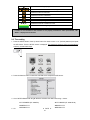
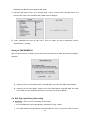
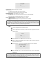
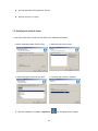
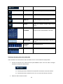
7-2. Installing the network viewer
1. Insert the provided CD in the CD drive and double-click “UMSClient(XXXX).exe”
2. Select a destination folder and click “Next”.
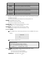
4. Select the program folder and click “Next”.
3. Select the type and click “Next”.
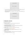
5. The setup status screen is displayed.
6. After the installation is completed, “UMS Client”
58
icon is displayed on the desktop.
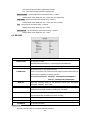
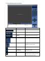
7-3. Live monitoring mode and functions.
Button
Function
Description
DATE & TIME
Displays the current date and time.
CONNECT/DISCONNECT
Connect/disconnect network connection..
SEARCH
Switches the live mode to search mode.
DISPLAY MODE
Select a channel and screen display mode.
PAN/TILT/ZOOM/ FOCUS
Control
the
PAN/TILT/ZOOM/FOCUS
features on the remote camera.
CAPTURE
Capture a still image from live screen.
PLAY/PAUSE
Play/pause live video.
ALARM
The ON/OFF button of the alarm output of
the DVR. When an alarm of the DVR is
output, this button becomes Red.
59
SETUP
Display the setup screen of the network
viewer.
HDD USAGE
DVR HDD storage Indicator.
NETWORK BANDWIDTH
Shows the transferred frames and network
bandwidth.
AUDIO
Adjust the volume. The audio can be turned
on or off by clicking the audio icon.
LOG WINDOW
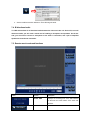
Operations of the display mode of the main screen
Single channel display - Click the one of channel button or double-click the channel screen.
QUAD/-screen display - Click the QUAD button to switch to quad-screen display
Full screen display - Click the maximize button to display only screen and hidden the operation panel.
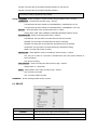
Image capture of live screen
Still-image of live screen can be captured and saved as BMP or JPEG file.
1. Click the channel to be captured. Then the channel screen is surrounded with a red line.
2. Click the CAPTURE button. Then the IMAGE CAPTURE dialog is displayed.
60
3. Set the conditions and click OK button. Then still-image is saved.
7-4. Bi directional audio
The UMS Client allows for bi directional audio between the client and a dvr unit. On the PC, to use bi
directional audio, you will need a sound card of handling a microphone and speakers. On the dvr
side, you will need to connect a microphone to the audio in connection, and a pair of amplified
speakers to the audio out connection.
7-5. Remote search mode and functions
Button
Function
Description
DATE & TIME
Displays the recording time of the data selected
on the time bar at the bottom of the main user
interface.
DISCONNECT
Disconnect network connection..
61
LIVE
Switches the search mode to live mode.
CAPTURE
Capture a still image from live screen.
MARK IN
Set the start time for video backup.
MARK OUT
Set the ending time for video backup.
BACKUP
Backup the selected recorded video as AVI
format.
SEARCH
The calendar shows dates with recorded video in
CALENDAR
a light blue and the selected date in dark blue.
TIMELINE BAR
The timeline shows recorded data in dark blue on
the bar.
PLAYBACK
The playback buttons.
BUTTON
DISPLAY MODE
Select a channel and screen display mode.
Searching and playing video in the remote DVR
Video recorded in the remote DVR or Video recorded on the PC can be searched and played back.
1.
Connect the network to the remote DVR and press SEARCH button. Then the mode is changed
from the live mode to the search mode.
2.
Searching the video recorded in the remote DVR: Connect the network to the DVR..
Searching the video recorded in the PC: Do not connect the network to the DVR.
Select the date to search the video.
62
3.
Drag the slid on the time scale and drop it between 0 to 24.
4.
Press the PLAY button. Then the video recorded in the remote DVR is played back.
Backup of video in the remote DVR
Video recorded in the remote DVR cab be backed up on the PC HDD as AVI format.
1. Connect the network to the remote DVR and play the video recorded in the remote DVR.
2. Drag the slid on the time scale and drop to the start time for video backup and press the MARK IN
button.
3. Drag the slid on the time scale and drop to the end time for video backup and press the MARK OUT
button. Then the marked time is displayed in dark green.
4. AVI Backup dialog is displayed. Click the OK button. Then the marked video is backed up.
63
Start time / Stop time: Backup time can be changed.
File path: Shows the folder that the backup file is recorded.
Channel: Shows backup channel..
7-6. PC System configuration
Click the SETUP button. Then the Setup dialog is displayed.
Setting General
Set security options, save path, and Automatic reconnection.
64
Security Option: Set a password for security options. When you access any of the selected
functions, you will need to enter the password.
Save Path: Specify the location to record for backup and still image capture.
Automatic reconnection: If a user selects this function, the client S/W will automatically try to
connect to the previously connected IP address if the network connection is lost.
Display network statistics: If a user selects this function, the client S/W will display network status,
Bit rate and Frame rate.
Time Format: Change the mode the Client software displays the time.
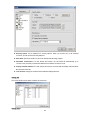
Setting Site
The remote DVRs can be added, modified, and removed.
Setting Event
65
Set the record path and the size of local disk space for the log files.
LOG – Select to save event log into ‘log file’.
ICON – Select to display the event on live video.
EVENT LIST – Select to show the event in the ‘Event List” window of live mode.
Search and check the recorded log data.
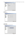
Setting Record
Set the recording conditions and select channels to record.
66
Select the local disk to use and the amount of disk space you want to allow the program to use for recording.
Setting Video
Set the video screen.
Setting Language
Select the language of the network client viewer.
67
8. Network – By an web-browser viewer
The DVR provides a live remote monitoring feature by web-browser viewer.
1. Check the IP address of the DVR from SETUP>SYSTEM>DESCRIPTION>IP ADDRESS.
2. Input the IP address or Domain name address that you pre-registered on www.ddnscenter.com on
the address field and press “Go”.
3. Click this bar. Then the dialog box is displayed.
4. Click “Install” to download ActiveX control.
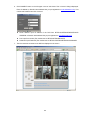
5. Web Browser Viewer is displayed as bellow.
68
6. Click CONNECT button on the Left upper corner of web-viewer. Then “Connect” dialog is displayed.
Enter IP address (or Domain name address that you pre-registered on www.ddnscenter.com), Port
number and Password and click “Connect”
Server address: Input IP address of the DVR from SETUP>SYSTEM>DESCRIPTION>IP
ADDRESS or Domain name address that you pre-registered on www.ddnscenter.com
Port: Input Port number (The number sets on SETUP>NETWORK>PORT)
Password: Input Password (The number sets on SETUP>SYSTEM>NETWORK PASSWORD
7. Then the cameras connected to the DVR are displayed on the screen.
69
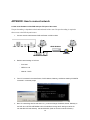
APPENDIX: How to connect network
A. How to set IP address of the DVR and open TCP port of the router?
The port forwarding is dependant on the brand and model of the router. The port forwarding is required to
allow access to the DVR beyond a router.
1.
Connect network cable between DVR and Router or ADSL modem.
ADSL Modem
Internet
IP Router or HUB
2.
3.
Default network setting on DVR are
-
Port: 5445
-
WEB Port : 80
-
Network : DHCP
From PC connected in the same Router, find IP address, Gateway, and Subnet mask by IPCONFIG
command in command prompt.
4.
But if IP is something else like 192.168.x.xxx., you should change IP address, Subnet, Gateway on
the DVR. Go to SETUP>NETWORK>LAN of the DVR and change the IP settings to be like IP:
192.168.XXX.XXX and Gateway: 192.168.XXX.XXX. (Refer to the user’s manual of Router.)
70
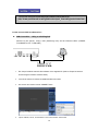
5.
Open your web browser. Enter the router IP address in the address bar (The router IP address are
different with the brand and model.), click GO.
6.
Enter the user name and password (admin is default) and press the OK button.
7.
Select the Port Range Forwarding tab.
8.
Enter the each field.
i.
Application: Enter a description of the DVR (Example: store1)
ii.
Start: Enter the first number of the port you need to port forward (Example: 5445)
iii.
End: Enter the last number of the port you need to port forward (Example: 5445)
iv.
Protocol: Select Both.
v.
IP address: Enter the IP address of the DVR on SETUP>NETWORK>LAN>IP ADDRESS.
vi.
Enable: Check the enable box.
9.
Select the Save settings button located on the bottom of the window. Then Port forwarding is finished.
71
You can learn how to port forward many kinds of Routers from the bellow site.
http://www.portforward.com/english/routers/port_forwarding/routerindex.htm
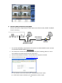
B. How to access DVR from Remote PC?
LAN Connection – Using a switching hub
Connect to the system, using a hub (Switching hub) and an Ethernet cable (10BASET/100BASE-TX CAT 5 LAN cable)
IP Router or HUB
1.
Run the pre-install the network client software on the supplied CD. (Refer to Chapter 6. Network
access using the Exclusive network viewer)
2.
Check the IP address from SETUP>SYSTEM>DESCRIPTION of DVR.
3.
Run network client software and click CONNECT button.
4.
Input IP address, Port No., and Password on the connect window. And click OK.
72
Internet (ADSL) Connection using DDNS
Connect to the system, using an Router or ADSL modem and an Ethernet cable (10BASE-T/100BASETX CAT 5 LAN cable)
ADSL Modem
Internet
IP Router or HUB
1.
Go to SETUP>NETWORK. Set NETWORK TYPE as DHCP and DDNS SERVER as ON. And make
sure that DDNS SERVER NAME is ddnscenter.com
2.
Go to Setup menu of Router and open TCP port 5445 using Port Forwarding. (Refer to A. How to
set IP address of the DVR and open TCP port of the router?)
3.
Confirm the Mac address and Serial No. from the label of the rear panel of the DVR.
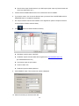
4.
Open the web browser and log on http://www.ddnscenter.com
MAC Address: Input the Mac address (EX. 0002690XXXXX) without a space.
Serial Number: Input the Serial No. (EX. 43000700XXX.) without a space.
73
Domain Name: Input Domain Name for your DVR system (Note. Input only Domain Name and
never input “ddnscenter.com”.)
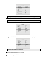
5.
Click the DUPLICATION CHECK button to see if the domain name is available.
6.
If you see the screen “You can use the Domain name you entered” then click RETURN and click
REGISTER button to complete the registration.
7.
Run the pre-install the network client software on the supplied CD. (Refer to Chapter 6. Network
access using the Exclusive network viewer)
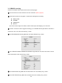
8.
Click
button and add the DVR as necessary.
Site Name: Input the name of the DVR.
IP Address: Input the Domain Name that is registered on http://www.ddnscenter.com
(EX. XXXXX.ddnscenter.com)
9.
Port Number: Input the port number.
Protocol: Select TCP.
Password: Input the network password.
Click CONNECT button. Then the Connect window is displayed.
10. Select the site that you access and click OK.
74
75