
1
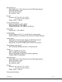
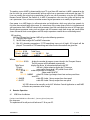
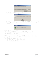
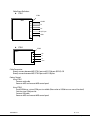
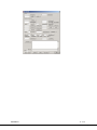
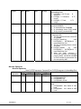
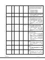
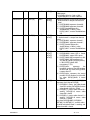
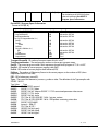
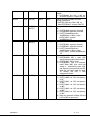
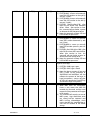
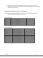
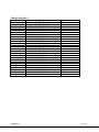
User’s Manual The most important thing we build is trust. Messenger Portable Decoder (MPD) 100-M0081X1 05/18/09 Cobham Surveillance GMS Products 1916 Palomar Oaks Way Ste 100 Carlsbad, CA 92008 T: 760-496-0055 F: 760-496-0057 www.cobham.com/gms TABLE OF CONTENTS 1 2 3 INTRODUCTION ........................................................................................................................................................ 3 TECHNICAL SPECIFICATIONS ....................................................................................................................... 3 MPD LOCAL CONTROL ........................................................................................................................................... 6 3.1 MPD Controls, Indicators and Connectors ................................................................................................. 6 3.1.1 Panels and Keys .................................................................................................................................................. 6 3.2 Operating Instructions – local .......................................................................................................................... 7 3.2.1 Standalone Operation without OSD ......................................................................................................... 7 3.2.2 Standalone Operation with OSD ................................................................................................................ 7 4 REMOTE OPERATION ............................................................................................................................................. 8 4.1 USB Driver Installation ......................................................................................................................................... 8 4.2 MPD Windows Control Panel Software........................................................................................................ 9 4.3 MPD Serial Port Communication Protocol .............................................................................................. 14 4.3.1 Protocol Format .............................................................................................................................................. 14 4.3.2 Command, Acknowledge and Warning ............................................................................................... 16 4.3.3 MPD Serial Port Communication Protocol - Quick reference ................................................... 25 100-M0081X1 2 of 29 www.cobham.com/gms 1 Introduction Messenger Portable Decoder (MPD) MPEG-2 Digital Audio/Video Decoder MPD Key Features Broadcast Quality 4:2:2 MPEG-2 Decoder Low Delay Compact Design Designed to mate with MSR Runs on 12VDC MPD with MSR Mounted The GMS Messenger Portable Decoder (MPD) is a compact professional 4:2:2 MPEG-2 digital audio/video decoder that is designed to be a companion to GMS’ MSR Diversity Receiver. A mounting plate is provided that allows the MSR to be mounted on top of the MPD. Two fans in the MPD provide cooling for both the MPD and the MSR. The ASI output of the MSR is feed into the MPD, which receives the MPEG2 TS stream, decodes it and output signals via analog video/audio ports, SDI/AES ports. These units can be controlled via either the RS-232C or USB control ports. An optional 19-inch Rack-Mounted shelf is available that can mount up to two MPD/MSR in just 5.25” of rack space. Additionally, an optional in-line AC/DC power supply is available. When used in conjunction with GMS’ MDT-B transmitter and MSR receiver, system latencies down to 2-3 frames are provided. The combination of Broadcast Quality Audio/Video and ultra-low latency make this system perfect for sports and ENG applications! 2 Technical Specifications Audio/Video Decoding Support ISO13818-1 TS demultiplexing (up to 32PID) Support ISO13818-2 (Main Profile @ Main Level and 422 Profile @ Main Level) video decoding Support ISO11172-3 and ISO13818-3 audio decoding, provide simultaneous 2 pairs of stereo (4 channels) decoding Support graphic display up to 16 bits/pel (OSD) 100-M0081X1 3 of 29 www.cobham.com/gms Transport Stream Input Type: DVB-ASI via BNC-F (Rear Panel) Rate: 1 b/Sec to 213 Mb/Sec TS Demultiplexing: In accordance with ISO13818-1 with up to 32 PIDs. Output Type: DVB-ASI loop via BNC-F (Rear Panel) Rate: 1 b/Sec to 213 Mb/Sec Video Decoding Type: MPEG-2 Standard: Supports ISO13818-2 Profiles: Main Profile @ Main Level, Simple Profile @ Main Level and 422 Profile @ Main Level Decoding Rates: 4:2:2 P@ML(1.5-50MHz) 4:2:0 MP@ML(1.5-15MHz) 4:2:0 SP@ML(1.5-15MHz) GOP Length: From adapt to input TS Video Outputs Analog Video Interface: Qty 2 CVBS w/OSD (Rear – BNC-F, Front – BNC-F) Video Format: PAL-B/G/I/M/N/D, NTSC, and SECAM L/B/G/K1 Screen Proportion: 4:3/16:9 Graphic Process: OSD, Support graphic display up to 16 bits/pel (OSD) Synchronization Information (Via DB-9M on rear panel) Video Synchronous Output SYNC Synchronous line/field/frame output Synchronous lock output 27M reference clock output Audio Outputs Analog Audio: 2 channels stereo, balanced via XLR-M on rear panel 2 channels stereo, un-balanced via RCA-F on front panel Digital Audio: 1 channel of AES/EBU-SPDIF via BNC-F on rear panel Status Indicators (Front Panel) LEDs: On/Standby, Decoder Lock Status, ASI Signal Present Control RS-232C via DB-9M on rear panel USB-1 via USB-Type A on rear panel Software: MS Windows Graphical User Interface Application (Windows 2000 & XP compatible.) 100-M0081X1 4 of 29 www.cobham.com/gms Electrical Features Power Supply: 9 to 17 VDC ( External In-Line AC PWR Supply Optional) Power Consumption: < 45W Pin1 and Pin 6 (9-17VDC) Pin 5 and Pin 9 (GND) Physical Dimensions: 8.5” (W) x 8.5” (D) x 1.0” (H) 21.6 cm x 21.6 cm x 2.54 cm Weight: 3.65 lbs ( 1.656 kg) Environmental Conditions Operating Temperature: 0 C 50 C Storage Temperature: -20 C 80 C Comparative Humidity: 10% ~ 90%, non-condensing Digital Video Interface: Qty 1 - SDI via BNC-F Audio Decoding Standard: Supports ISO11172-3 and ISO13818-3 audio decoding Number of Outputs: simultaneous 2 pairs of stereo (4 channels) decoding Audio Outputs Analog Audio: 2 channels stereo, balanced via XLR-M on rear panel 2 channels stereo, un-balanced via RCA-F on front panel Digital Audio: 1 channel of AES/EBU-SPDIF via BNC-F on rear panel Status Indicators (Front Panel) LEDs: On/Standby, Decoder Lock Status, ASI Signal Present Control RS-232C via DB-9M on rear panel USB-1 via USB-Type A on rear panel Software: MS Windows Graphical User Interface Application (Windows 2000 & XP compatible.) Electrical Features Power Supply: 9 to 17 VDC ( External In-Line AC PWR Supply Optional) Power Consumption: < 45W Pin1 and Pin 6 (9-17VDC) Pin 5 and Pin 9 (GND) Physical Dimensions: 8.5” (W) x 8.5” (D) x 1.0” (H) 21.6 cm x 21.6 cm x 2.54 cm Weight: 3.65 lbs ( 1.656 kg) Environmental Conditions 100-M0081X1 5 of 29 www.cobham.com/gms Operating Temperature: 0 C 50 C Storage Temperature: -20 C 80 C Comparative Humidity: 10% ~ 90%, non-condensing 3 3.1 MPD Local Control MPD Controls, Indicators and Connectors 3.1.1 Panels and Keys Front Panel: Where: POWER PWR TS LOCK 1/R 1/L 1/CVBS :Power Switch :Power On/Standby Indication :ASI Signal Present Status :Decoder Lock Status :Analog Audio Signal /Channel 1 /Right :Analog Audio Signal /Channel 1 /Left :Composite Video Broadcast Signal, Channel 1 Rear Panel: Where; ASI IN :Asynchronous Serial Interface Signal Input ASI OUT :Asynchronous Serial Interface Signal Output SDI :Serial Digital Interface Digital Video Output AES :Advanced Encryption Standard digital Audio Output 2/CVBS:Composite Video Broadcast Signal, Channel 2 2/R :Analog Audio Signal /Channel 2 /Right 2/L :Analog Audio Signal /Channel 2 /Left CTRL1 :RS232 Interface CTRL2 :USB Interface POWER :DC Power Line 100-M0081X1 6 of 29 www.cobham.com/gms MPD has three status indicators and analog A/V output interfaces on the front panel, and various interfaces on the rear panel. There are power switch, power/standby, TS and Lock indication LEDs and analog A/V output interfaces of channel 1 on the front panel. There is a pair of DVB ASI interfaces on the rear panel for receiving MPEG-2 TS and loop back. The rear panel provides analog A/V output interfaces of channel 2 and digital A/V interface. RS232 interface on the rear panel is for upgrading micro-code and sending out test signal comprised 27 MHz clock and h/v sync. . All kinds of local control and operation can be executed through RS232 or USB interface. 3.2 Operating Instructions – local For single-program Transport Streams (TSs), like those that are typically output from GMS’ Wireless Audio/Video Links, the Messenger Portable Decoder (MPD) is a plug & play device. It will automatically select and decode any compliant compressed Video or Audio and provide uncompressed outputs. With the OSD function turned-off, the user can monitor status via the MPD’s Front Panel LEDs. With the OSD function turned on, the video output provides additional information on the incoming stream. See Section 3.2.2. The OSD function and all other MPD controls can be controlled using the MPD M.S. Windows Control Panel Software. See Section 4. 3.2.1 Standalone Operation without OSD Before activating MPD, please carefully check all the cable connections and ensure that the appropriate power supply voltage (+12 VDC) is applied to the unit. Connection between RS232 or USB interface and PC is not necessary, which is generally used when micro-code is to be updated and operational parameters need to be set by remote control application. Once power is on, MPD begins its self-examination and initialization, which may take a few seconds. At this time, the monitor displays blue screen. It is normal even if the screen jitters a little. As initialization and self-examination finish, MPD will setup initial parameters from flash and check the status of ASI input port. Should relevant unit and TS parameter setting turn out correct, both image and sound will be shown. Otherwise, black screen appears and the MPDs PID analysis operations will be run until a properly formatted TS is supplied to the MPD’s ASI input 3.2.2 Standalone Operation with OSD Before activating MPD, please carefully check all the cable connections and ensure that the appropriate power supply voltage (+12 VDC) is applied to the unit. Connection between RS232 or USB interface and PC is not necessary, which is generally used when micro-code is to be updated and operational parameters need to be set by remote control application. The MPD has a clear-cut and automatic OSD display. Users will easily find out operation information according to the decoder. OSD Screen structure is given as: PROGRAM 01/03 TS Lock ! MP @ ML PID VID: 0x006F 100-M0081X1 Table Tennis SAMP 44100 SPS PAL A1: 0x0070 A2: 0x1FFF 7 of 29 www.cobham.com/gms The working status of MPD is determined by input TS signal from ASI interface. As MPD is powered-on for the first time, the system will automatically pick up original set-up parameters and examine the input TS. Users can modify the original set-up parameters to get a new set of parameters using the M.S. Windows Remote Control Software. See Section 4. As MPD is powered on next time, the system will pick up the user’s parameters. Users, of course, can either recover original parameters or re-modify the parameters. Once power is on, MPD begins its self-examination and initialization, which may take a few seconds. At this time, the monitor displays blue screen. It is normal even if the screen jitters a little. As initialization and self-examination finish, MPD will setup initial parameters from flash and check the status of ASI input port. Should relevant parameter setting turn out correct and ASI connects ready, both image and sound will be shown. Otherwise, black screen appears and PID analysis operations need to be run under background. PID searching: MPD has PID searching function. MPD will go to the following operations: 1) Check ASI input signal 2) Set PID filters and get PAT and PMT information 3) Set A/V decoder parameters. If PID searching turns out all right, A/V signal will be played. The results of PID searching and other mode information are given as: PROGRAM 01/03 TS Lock ! MP @ ML PID VID: 0x006F Table Tennis SAMP 44100 SPS PAL A1: 0x0070 A2: 0x1FFF Where: PROGRAM 01/03 :display the number of program streams found in the Transport Stream. The first program will be decoded automatically. Table Tennis :display the service_id information defined in the SDT. TS Lock ! :ASI link is stable, otherwise display No TS message MP @ ML :main profile @ main level / 422 profile @ main level SAMP 44100 SPS :audio sample ratio 44.1k/48k/32k PAL :Video mode PAL/NTSC PID VID: 0x006F :video PID, Video signal output from front and rear panel have same PID A1: 0x0070 :audio PID. Audio 1 always output from front panel. A2: 0x1FFF :audio PID. Audio 2 always output from rear panel. *A/V PID value can be manually set by M.S. Windows Control Application as well. MPD will retain new parameters after change. 4 4.1 Remote Operation USB Driver Installation Find pre‐install USB drivers file under \..\current_driver\setup.exe Run setup.exe. This operation will install pre-install software V1.16 to your PC. 100-M0081X1 8 of 29 www.cobham.com/gms Press “Install”, then wait till the install process finishes. After finishing pre-install driver, user can connect USB cable to MPD. This time new message windows will pop up. OS finds a new hardware. Wait for OS to close all message windows. After completely install USB driver, user can configure USB to UART port as your wish 4.2 MPD Windows Control Panel Software MPD Control panel software is only a demo program for MPD serial port communication protocol. System Requirements: PC with free ASC0 channel or free USB channel Windows 95 and above, Windows NT 4.0 and above One serial cable or USB cable 100-M0081X1 9 of 29 www.cobham.com/gms Cable Pinout Definition: CTRL1 CTRL1 MPD 1 2 3 4 5 6 12VDC 7 8 GND Tx Rx H/V Sync CTRL2 CTRL2 MPD 1 2 VCC D‐ D+ 3 GND Cable Connection: Directly connect between MPD CTRL1 port and PC COM port (RS232) OR Directly connect between MPD CTRL2 port and PC USB port Getting Started: Using CTRL1 Connect serial cable Power on MPD and execute MPD control panel Using CTRL2 Install USB driver, a virtual COM port is available (Please refer to USB driver user manual for detail) Find the virtual COM port No. Connect USB cable. Power on MPD and execute MPD control panel. 100-M0081X1 10 of 29 www.cobham.com/gms 100-M0081X1 11 of 29 www.cobham.com/gms Open COM port and press “Open” button. E.g. if COM 1 is connected with CTRL0, fill 1 at COM item, “Open” it, you can control MPD using serial port. If COM 3 is connected with CTRL2, fill 3 at COM item, “Open” it, you can control MPD using USB port. Open a corresponding port first when you execute this control panel. “LinkTest”: “SysRst”: Test the serial port connection between Host and MPD. Reset on MPD When you press this button, MPD needs around 20 seconds to initialize. “PresetPara” Restore default parameters. When you press this button, it will cause the re-start of MPD system. System Table “GetSoftVer”: Read MPD software version number “GetAsiInput” Read the TS status of MPD ASI input. It is a decimal value. value.0: 1 --- with TS input; 0 --- without TS. value.1: 1 --- TS abnormal; 0 --- TS normal. value.2: 1 --- TS lock; 0 --- TS unlock. value.3 – value.7 is fixed 0 e.g. if the value = 5 means the input TS stream is normal and locked. “GetID” Get the ID number of the currently connected MPD. Note: you must fill 0 at blank item and press the “GetID” button, you can get correct ID value. “SetID” Set new ID number for the currently connected MPD. Fill the new ID number, press the “SetID” button. Monitor and Control Table 100-M0081X1 Get MPD System Information. 12 of 29 www.cobham.com/gms “GetTvMode” “GetVideoSpec” “GetAudioSamp” “GetVideoPID” “SetVideoPID” “GetSelProg” “SetSelProg” Read the current video output mode. 0 means NTSC 1 means PAL 2 means SECAM Read the current video syntax subset and level. 0 means MainProfile @ Main Level 1 means 4:2:2 Profile @ Main Level Read current audio sampling rate. As MPD’s two audio channels can only work on the same sampling rate, so the reads apply to both of the audio channels at the same time. 0 means 48k/s 1 means 44.1K/s 2 means 32K/s Read current video PID. Set current video PID. e.g. fill 0x01C2 at the left blank item and press the “SetVIdeoPID” button. It means that the VideoPID is set as 0x01C2. Read the program number of the current program being played. e.g. 1 means Program 1 is playing. Set the number of program which is playing. e.g. fill 3 at the left blank item and press the “SetSelProg” button. It means Channel 3 program is playing. “GetBright” “SetBright” “GetContrast” “SetContrast” “GetHue” “SetHue” “GetColor” “SetColor” “GetAudioPID” “SetAudioPID” “GetAudioVolume” 100-M0081X1 Read the brightness of current analog video output. Set the brightness of current analog video output. e.g. fill 55 at the left blank item and press the “SetBright” button. It means Bright=55. 0<=Bright<=100 is available. Read the contrast of current analog video output. Set the contrast of current analog video output. e.g. fill 55 means Contrast=55. 0<=Contrast<=100 is available. Read the hue of current analog video output. Set the hue of current analog video output. e.g. fill 55 means Hue=55. 0<=Hue<=100 is available. Read the color of current analog video output. Set the color of current analog video output. e.g. fill 55 means Color=55. 0<=Color<=100 is available. Read PID of audio channel 1 and audio channel 2. Fill 0 at “Channel:” item and press “GetAudioPID”, you can get PID of audio channel 1. Fill 1 at “Channel:” item and press “GetAudioPID”, you can get PID of audio channel 2. Except for 0 and 1, the others are invalid. Set PID of audio channel 1 and audio channel 2. e.g. fill 0 at “Channel:” item and fill 0x01C2 at “AudioPID” item, then press “SetAudioPID”. It means set Audio channel 1 PID = 0x01C2. Fill 1 at “Channel:” item and fill 0x01C2 at “AudioPID” item, then press “SetAudioPID”, It means set Audio channel 2 PID = 0x01C2. Read the volume of audio channel 1 and audio channel 2. Fill 0 at “Channel:” item and press “GetAudioVolume”, you can get PID of audio channel 1. 13 of 29 www.cobham.com/gms “SetAudVol” “GetOsdStatus” “SetOSDOnOff” “SetOSDTnsp” “Left” “Right” 100-M0081X1 Fill 1 at “Channel:” item and press “GetAudioVolume”, you can get PID of audio channel 2. Except for 0 and 1, the others are invalid. Set the volume of audio channel 1 and audio channel 2. e.g. fill 0 at “Channel:” item and fill 55 at “AudioVolume” item, then press “SetAudVol”. It means set Audio channel 1 volume = 55. Fill 1 at “Channel:” item and fill 55 at “AudioVolume” item, then press “SetAudVol”, It means set Audio channel 2 volume = 55 . Read current OSD status. “OSDOnOff:” = 1, means OSD is close; “OSDOnOff:” = 0, means OSD is open; “OSDTnsp:” =0, means OSD transparency is 0%; “OSDTnsp:” =1, means OSD transparency is 25%; “OSDTnsp:” =2, means OSD transparency is 50%; “OSDTnsp:” =3, means OSD transparency is 75%; “xPos:” represents the horizontal position of the OSD window. 0<=xPos<=80 is available. “yPos:” represents the vertical position of the OSD window. 0<=yPos<=40 is available. Open or close OSD Fill 0 at “OSDOnOff” item and press “SetOSDOnOff” button. It means that OSD is open. Fill 1 at “OSDOnOff” item and press “SetOSDOnOff” button. It means that OSD is close. Fill 2 at “OSDOnOff” item and press “SetOSDOnOff” button. It means that OSD is in auto-matic mode. When MPD finds some info change, it automatically opens OSD, and displays the change info on the OSD. When the info keeps stable for about 10 seconds, the OSD is then automatically closed. Set up OSD transparency. Fill 0 at “OSDTnsp” item and press “SetOSDTnsp” button. Set OSD transparency as 0%. Fill 1 at “OSDTnsp” item and press “SetOSDTnsp” button. Set OSD transparency as 20%. Fill 2 at “OSDTnsp” item and press “SetOSDTnsp” button. Set OSD transparency as 40%. Fill 3 at “OSDTnsp” item and press “SetOSDTnsp” button. Set OSD transparency as 60%. Fill 4 at “OSDTnsp” item and press “SetOSDTnsp” button. Set OSD transparency as 80%. This command will keep OSD and LOGO of MPD in open status. Set up OSD horizontal position. Press “Left” button, means to horizontally move the OSD window to the left (2 pixels) . Press “Right” button, means to horizontally move the OSD window to the right (2 pixels) . 14 of 29 www.cobham.com/gms “Up” “Down” GetPsiInfo Set up OSD vertical position. Press “Up” button, means to vertically move the OSD window upward (2 pixels) . Press “Down” button, means to vertically move the OSD window downward (2 pixels) . Get TS Stream PSI Information. Press “GetPsiInfo” to read PSI information of current bit stream. Please refer to “MPD Serial Port Communication Protocol” for details. 4.3 MPD Serial Port Communication Protocol MPD MPEG-2 Decoder has one RS232 serial port and one USB interface. The external equipment (usually PC or Host) can achieve the monitoring and control on the working status of MPD, which makes it easy for the applications such as secondary development, production test, engineering commissioning and operation maintenance, etc. This file consists of the following parts: MPD serial port communication mode (equivalent to physical layer); Protocol format of the serial port communication between MPD and monitoring program; Handshake acknowledge time order of MPD serial port communication; Host monitoring program: the host can monitor the operation status and execute control on MPD by the monitoring program. Serial Port Communication Mode Serial Port Communication Mode is as follows: Serial Port Communication Mode Serial Port Parameters Communication Mode Start 1 bit Stop 1 bit Data 8 bits Odd-even check No Baud Rate 38400bps Flow Control No (Normal Mode) 4.3.1 Protocol Format Data Frame Format Data Frame Format includes Command Format, Acknowledge Format and Warning Format. Command Format is the command data format that the host monitoring program sends to MPD; Acknowledge Format is data format that MPD acknowledges the host monitoring program; Warning Format is warning information that MPD initiatively submit to the host monitoring program. 100-M0081X1 15 of 29 www.cobham.com/gms Command Format SYNH ID 1B 2B 0xAA ID number of the connected MPD LENH LENL 1B 1B Length of (CMD+DATA) In unit of Byte Acknowledge Format SYNH ID LENH LENL 1B 2B 1B 1B 0xAA ID number Length of of the MPD (ACK+DATA) In unit of Byte Warning Format SYNH ID LENH LENL 1B 2B 1B 1B 0xAA ID number Length of of the MPD (WARN+DATA), In unit of Byte CMD 1B Command Code ACK 1B Acknowledg e Code WARN 1B Warning Code 0x11 DATA (LENH/LENL)B N Bytes of optional DATA SUM 1B Sum of (ID,LENH, LENL,CMD,DAT A) SYNE 1B 0x55 DATA (LENH/LENL)B N Bytes of optional DATA SUM SYNE 1B 0x55 DATA 4B or 1B 4 or 1 bytes of DATA 1B Sum of (ID,LENH, LENL,ACK,DATA) SUM 1B Sum of (ID,LENH, LENL,WARN,DAT A) SYNE 1B 0x55 Definition of Data Segment Data Definition and Explanation Segm ent SYNH Sync. flag is 0xAA. ID number for each MPD. The monitoring program should use the right ID number to ID communicate with the corresponding MPD. ID=0x0000 refers to one reserved ID, and the monitoring program can use ID=0x0000 to communicate with any one of MPD. Data length LENH and LENL form one 16bit unsign integer. It represents the DATA length, LENH high byte the unit is in byte. When there is no data, the value is 0. Data length LENL low byte Command code, which refers to the command that the monitoring program sends to MPD. CMD Acknowledge code, which refers to the acknowledge that MPD sends to the monitoring program. ACK When the command is successfully executed, ACK=CMD, or otherwise, ACK=0x00. Warning code, which refers to the warning that MPD initiatively sends to the monitoring WAR program. Its value is always 0x11. N DATA In Command or Acknowledge frame, it is an optional item, and its length is changeable. In Warning frame, it shows 4 or 1 byte warning information. SUM Check summary,which is the byte summary of LENH, LENL, CMD/ACK, DATA, carry omitted. SYNE Sync. End, total is 0x55. 100-M0081X1 16 of 29 www.cobham.com/gms The range of DATA length value is 0~2040. When DATA length is 2040, (LENH/LENL)= 0x07F8. The whole data frame length at this time happens to be 2048B (1B SYNH + 2B ID + 2B LENH/LENL + 1B CMD/ACK + 2040B DATA + 1B SUM + 1B SYNE). 4.3.2 Command, Acknowledge and Warning The command and acknowledge of MPD include the following three operations: System operation, Monitor operation, Control operation. In addition, MPD has the function of automatic alarming. System Operation System Operation Note: DATC[X] represents command data, DATA[X] represents acknowledge data System Operation Command CMD DATA Acknowledge ACK LinkTest 0xFF None 0xFF None SoftVer 0xFE None 0xFE DATA[0..1] SysRst 0xFD None 0xFD None 100-M0081X1 Explanations DATA Test the serial port connection between Host and MPD. 1) Before sending out other commands, Host should first send LinkTest command to make sure that the serial port communication is working fine. 2) Host can also periodically send out this test command to execute the real-time monitoring on the serial port connection status. Read MPD software version number. 1) In Acknowledge frame, DATA[0] is the integer part of the version number, and DATA[1] is the decimal part of the version number. E.g. when DATA[0]=0x02, DATA[0]=0x04, this means the software version number is Ver2.4. Reset on MPD 1) When Host sends out this command and receives the acknowledge frame of MPD, it only means that MPD has received the SysRst command, and it does not mean the reset has done. It usually takes around 20 seconds for MPD to initialize; 2) Host should then send out several LinkTest commands until it receives the LinkTest acknowledge from MPD, which means that MPD has completed the reset. 17 of 29 www.cobham.com/gms AsiInput 0xFC None 0xFC DATA[0] GetID 0xFB None 0xFB None SetID 0xFA DATC[0..1] 0xFC DATA[0..1] Read the TS status of MPD ASI input. In acknowledge frame, 1) DATA[0].0: 1, with TS input; 0, without TS. 2) DATA[0].1: 1, TS abnormal; 0, TS normal. 3) DATA[0].2: 1, TS lock; 0, TS unlock. Get the ID number of the currently connected MPD的ID. 1) In command frame, ID=0x0000; 2) In acknowledge frame, ID=ID number of the currently connected MPD. Set new ID number for the currently connected MPD. 1) The ID in command frame is the old ID or is 0x0000; 2) DATC[0..1]=NewID,e.g. when DATC[0]=0x12, DATC[0]=0x34, it means NewID=0x1234; 3) The ID in acknowledge frame is the old ID number; 4) DATA[0..1]=NewID, e.g. when DATA[0]=0x12, DATC[0]=0x34, it means NewID=0x1234; 5) When the SetID command is successfully executed, the monitoring program should use NewID or 0x0000 as the ID number to communicate with the corresponding MPD. Monitor Operation Monitor Operation Note: DATC[X] represents Command Data, DATA[X] represents Acknowledge Data Monitor Operation TvMode Command CMD DATA 0xEF None Acknowledge ACK DATA 0xEF DATA[0] VideoSpec 0xEE 0xEE 100-M0081X1 None DATA[0] Explanation Read the current video output mode. 1) DATA[0]=0x00 NTSC 2) DATA[0]=0x01 PAL 3) DATA[0]=0x02 SECAM Read the current video syntax subset and level. 1) DATA[0]=0x00 Main Profile @ Main Level 2) DATA[0]=0x01 4:2:2 Profile @ Main Level 18 of 29 www.cobham.com/gms AudioSamp 0xED None 0xED DATA[0] VideoPID 0xEC None 0xEC DATA[0..1] Audio0PID 0xEB DATC[0] 0xEB DATA[0] DATA[1..2] Audio1PID 0xEB DATC[0] 0xEB DATA[0] DATA[1..2] SelProg 0xEA None 0xEA DATA[0..1] Bright 0xE9 None 0xE9 DATA[0] Contrast 0xE8 None 0xE8 DATA[0] Hue 0xE7 None 0xE7 DATA[0] 100-M0081X1 Read current audio sampling rate. As MPD’s two audio channels can only work on the same sampling rate, so the reads apply to both of the audio channels at the same time. 1) DATA[0]=0x00 48000k/s 2) DATA[0]=0x01 44100k/s 3) DATA[0]=0x02 32000k/s Read current video PID. 1) DATA[0..1] = VideoPID, little endian; e.g. when DATA[0]=0x01, DATA[1]=0xC2, it means VideoPID = 0x01C2. Read PID of current audio channel 0. Audio channel 0 is output from the front panel. 1) DATC[0]=0x00 represents channel 0; 2) DATA[0]=0x00 represents channel 0; 3) DATA[1..2]=Audio1PID, little endian; e.g. when DATA[1]=0x02, DATA[2]=0xC2, it means Audio0PID = 0x02C2. Read PID of current audio channel 1. Audio channel 1 is output from the rear panel. 1) DATC[0]=0x01, represents channel 1; 2) DATA[0]=0x01, represents channel 1; 3) DATA[1..2]=Audio1PID, little endian; e.g. when DATA[1]=0x02, DATA[2]=0xC3, it means Audio1PID = 0x02C3. Read the program number of the current program being played. 1) DATA[0..1]=ProgNumber, little endian; e.g. when DATA[0]=0x00, DATA[1]=0x01, it means Program 1 is playing; when DATA[0]=0x00, DATA[1]=0x10, it means program 16 is playing; when DATA[0]=0x00, DATA[1]=0x00, it means no program is currently playing. Read the brightness of current analog video output. 1) DATA [0]=Bright, 0<=Bright<=100, e.g. when DATA[0]=0x37, it means Bright=55. Read the contrast of current analog video output. 1) DATA[0]=Contrast, 0<=Contrast <=100, e.g. when DATA[0]=0x37, it means Contrast=55. Read the hue of current analog video output. 1) DATA[0]=Hue, 0<= Hue <=100, e.g. when DATA[0]=0x37, it means Hue =55. 19 of 29 www.cobham.com/gms Color None 0xE6 DATA[0] Audio0Volume 0xE5 DATC[0] 0xE5 DATA[0] DATA[1] Audio1Volume 0xE5 DATC[0] 0xE5 DATA[0] DATA[1] OsdStatus 0xE4 None 0xE5 DATA[0] DATA[1] DATA[2] DATA[3] DecStatus 0xE3 None 0xE4 DATA[0] 100-M0081X1 0xE6 Read the color saturation of current analog video output. 1) DATA[0]= Color, 0<= Color <=100, e.g.DATA[0]=0x37, it means Color=55. Read the volume of current audio channel 0. Audio channel 0 is output from the front panel. 1) DATC[0]=0x00, represents channel 0; 2) DATA[0]=0x00, represents channel 0; 3) DATA[1]=Audio0Volume, 0<= Audio0Volume <=100, e.g. when DATA[1]=0x37, it means Audio0Volume =55. Read the volume of current audio channel 1. Audio channel 1 is output from the rear panel. 1) DATC[0]=0x01, represents channel 1; 2) DATA[0]=0x01, represents channel 1; 3) DATA[1]=Audio1Volume, 0<= Audio1Volume <=100, e.g. when DATA[1]=0x37, it means Audio0Volume =55. Read current OSD status. 1) DATA[0]=0x00, means OSD is closed; DATA[0]=0x01, means OSD is open. 2) DATA[1]=0x00, OSD transparency is 0%; DATA[1]=0x01, OSD transparency is 25%; DATA[1]=0x02, OSD transparency is 50%; DATA[1]=0x03, OSD transparency is 75%; 3) DATA[2]=xPos, represents the horizontal position of the OSD window, 0<=xPos<=80; e.g. when DATA[2]=0x20, it means xPos=32; 4) DATA[3]=yPos, represents the vertical position of OSD window, 0<=yPos<=40; e.g. when DATA[3]=0x20, it means yPos=32. Read the current decode status. DATA[0].X represents the X digit of DATA[0]. 1) DATA[0].0=1, means the video decode channel is working, DATA[0].0=0, means video decode channel is closed; 2) DATA[0].1=1, means audio channel 0 is working, DATA[0].1=0, means audio channel 0 is closed; 3) DATA[0].2=1, means audio channel 1 is working, DATA[0].2=0 means audio channel 1 is closed; e.g. when DATA[0]=0x05, DATA[0].0=1, DATA[0].1=0, DATA[0].2=1, it means video channel and audio channel 1 is working, and video channel 0 is closed. 20 of 29 www.cobham.com/gms PsiInfo 0xE2 None 0xE3 DATA[0..N] Read PSI information of current bit stream. For the definition of DATA[0..N], please refer to the following Get MPEG-2 Program Specs Information Get MPEG-2 Program Specs Information Format of DATA[0..N]. Program Specs Information DATA[0..N] Syntax MPEG2_PSI() TransportStreamId TotalProgramNumber For (I=0; I< ProgramNumber; I++) PmtID PmtPid PcrPid PidNum For(j=0; J< PidNum; J++) PID Type ProviderName ProgramName No. Byte Data Type 2B 2B little endian, INT16U little endian, INT16U 2B 2B 2B 2B little endian, INT16U little endian, INT16U little endian, INT16U little endian, INT16U 2B 2B 20B 20B little endian, INT16U little endian, INT16U Char * Char * TransportStreamId - ID number of transport steam which is in PAT[1]. TotalProgramNumber - The total program numbers in the current transport stream. PmtID - The current program number, which represents channel PmtID program of TS. It is in PAT. PmtPid - PID number of current program mapping table (PMT). PcrPid - PID number of current program clock reference(PCR). PidNum - The numbers of Elementary Stream in the current program, or the numbers of PID (when independent PcrPID is not used). PID - PID of elementary stream(ES). Type – The type of the elementary stream, e.g. audio or video. The definition of the Type complies with ISO/IEC 13818-1: Type Value 0x0000 0x0001 0x0002 0x0003 0x0004 0x0005 0x0006 0x0007 0x0008 0x0009 0x000A 0x000B 0x000C Type ITU-T | ISO/IEC reserved ISO/IEC 11172-2 Video ISO/IEC 13818-2 Video or ISO/IEC 11172-2 constrained parameter video stream ISO/IEC 11172-3 Audio ISO/IEC 13818-3 Audio ITU-T Rec. H.222.0 | ISO/IEC 13818-1 private_sections ITU-T Rec. H.222.0 | ISO/IEC 13818-1 PES packets containing private data ISO/IEC 13522 MHEG Annex A – DSM CC ITU-T Rec. H.222.1 ISO/IEC 13818-6 type A ISO/IEC 13818-6 type B ISO/IEC 13818-6 type C [1] Refer to ISO/IEC 13818-1 100-M0081X1 21 of 29 www.cobham.com/gms 0x000D ISO/IEC 13818-6 type D 0x000E ISO/IEC 13818-1 auxiliary 0x000F-0x007F ITU-T Rec. H.222.0 | ISO/IEC 13818-1 reserved 0x0080-0x00FF User private ProviderName - is a character string with fixed length (20B) in which the name of the program provider is stored. When the length of provider name is less than 20B, the rest characters are filled up with 0. It is stored in SDT[2]. ProgramName - is a character string with fixed length (20B) in which the name of the program is stored. When the length of the program name is less than 20B, the rest characters are filled up with 0. It is stored in SDT. Control Operation Note: DATC[X] represents command data, DATA[X] represents acknowledge data Control Command Acknowledge Explanation Operation CMD DATA ACK DATA SetVidPID 0xCF DATC[0..1] 0xCF None Set up current video PID. 1) DATC[0..1] = VideoPID, e.g. when DATC[0]=0x01, DATC[1]=0xC2, it means that the VideoPID is set as 0x01C2. SetAud0PID 0xCE DATC[0] 0xCE DATA[0] Set up PID of current audio channel 0. DATC[1..2] 1) DATC[0]=0x00, represents channel 0; 2) DATA[0]=0x00, represents channel 0; 3) DATC[1..2]=Audio0PID, e.g. when DATC[1]=0x01, DATC[2]=0xC3, it means Audio0PID = 0x01C3. SetAud1PID 0xCE DATC[0] 0xCE DATA[0] Set up PID of current audio channel 1. DATC[1..2] 1) DATC[0]=0x01, represents channel 1; 2) DATA[0]=0x01, represents channel 1; 3) DATC[1..2]=Audio1PID, e.g. when DATC[1]=0x01, DATC[2]=0xC4, it means Audio1PID = 0x01C4. SetProgNo 0xCD DATC[1..2] 0xCD None Set up the number of program which is playing. 1) DATC[0..1]=ProgNumber, e.g. when DATC[0]=0x00, DATA[1]=0x00, it means Channel 0 program is playing; when DATA[0]=0x00, DATA[1]=0x10, it means Channel 16 program is playing. SetBright 0xCC DATC[0] 0xCC None Set up the brightness of current analog video output. 1) DATC [0]=Bright, 0<=Bright<=100, e.g. when DATC[0]=0x37, it means Bright=55. SetContrast 0xCB DATC[0] 0xCB None Set up the contrast of current analog video output. 1) DATC[0]=Contrast, 0<=Contrast <=100, e.g. when DATC[0]=0x37, it means Contrast=55. [2] DVB EN 300 468 100-M0081X1 22 of 29 www.cobham.com/gms SetHue 0xCA DATC[0] 0xCA None SetColor 0xC9 DATC[0] 0xC9 None SetAud0Vol 0xC8 DATC[0] DATC[1] 0xC8 DATA[0] SetAud1Vol 0xC8 DATC[0] DATC[1] 0xC8 DATA[0] SetOSDOnoff 0xC7 DATC[0] 0xC7 None SetOSDTnsp 0xC6 DATC[0] 0xC6 None 100-M0081X1 Set up the hue of current analog video output. 1) DATC[0]=Hue, 0<= Hue <=100, e.g. when DATC[0]=0x37, it means Hue =55. Set up the color saturation of current analog video output. 1)DATC[0]= Color, 0<= Color<=100, e.g. when DATC[0]=0x37, it means Color=55. Set up the volume of current audio channel 0. 1) DATC[0]=0x00, represents channel 0; 2) DATA[0]=0x00, represents channel 0; 3) DATC[1]=Audio0Volume, 0<= Audio0Volume <=100, e.g. when DATA[1]=0x37, it means Audio0Volume=55. Set up the volume of current audio channel 1. 1) DATC[0]=0x01, represents channel 1; 2) DATA[0]=0x01, represents channel 1; 3) DATC[1]=Audio1Volume, 0<= Audio1Volume <=100, e.g. when DATC[1]=0x37, it means Audio0Volume =55. Open or close OSD 1) DATC[0]=0x00, OSD is open. OSD displays operating information of MPD. 2) DATC[0]=0x01, OSD is closed; 3) DATC[0]=0x02, OSD is in automatic mode. When MPD finds some info change, it automatically opens OSD, and display the change info on the OSD. When the info keeps stable for about 10 seconds, the OSD is then automatically closed. Set up OSD transparency. 1) DATC[1]=0x00, set OSD transparency as 0%; 2) DATC[1]=0x01, set OSD transparency as 20%; 3) DATC[1]=0x02, set OSD transparency as 40%; 4) DATC[1]=0x03, set OSD transparency as 60%; 5) DATC[1]=0x04, set OSD transparency as 80%. 6) Note: this command will keep OSD and LOGO of MPD in open status. 23 of 29 www.cobham.com/gms SetOSDPosX 0xC5 DATC[0] 0xC5 DATA[0] SetOSDPosY 0xC4 DATC[0] 0xC4 DATA[0] LogoOnoff 0xC3 DATC[0] 0xC3 None Set up OSD horizontal position. 1) DATC[0]=0x01, it means to horizontally move the OSD window to the right by one unit (2 pixels) . 2) DATC[0]=0x00, it means to horizontally move the OSD window to the left by one unit (2 pixels). 3) DATA[0]= xPos(0<=xPos<=120). xPos refers to the current OSD horizontal offset. When xPos reaches its limit, this command will not further increase or decrease the OSD horizontal offset. 4) Note: this command will keep OSD and LOGO of MPD in open status. Set up OSD vertical position. 1) DATC[0]=0x01, it means to vertically move OSD window downward by one unit (2 lines); 2) DATC[0]=0x00, it means to vertically move OSD window upward by one unit (2 lines); 3) DATA[0]= yPos(160<=yPos<=200). yPos refers to the current OSD vertical offset. When yPos reaches its limit, this command will not further increase or decrease the OSD vertical offset. 4) Note: this command will keep OSD and LOGO of MPD in open status. Open or close Logo。 1) DATC[0]=0x00, Logo is open; PresetPara 100-M0081X1 0xC2 None 0xC2 None 2) DATC[0]=0x01, Logo is closed. 3) Note: the relative position of logo and OSD is fixed, so the commands of SetOSDPosX and SetOSDPosY will also influence the position of the Logo. As Logo’s transparency consists with that of OSD, the command of SetOSDTnsp also influence Logo’s transparency. Restore default parameters. 1) When MPD sends out acknowledge frame, it only means that MPD has received this command, and the actual restore of all the parameters will happen in 20 seconds. 2) This command will cause the re-start of MPD system. Host should then sends out several LinkTest command until MPD’s LinkTest acknowledges, which means that MPD has completed the restart and has restored all the default settings. 24 of 29 www.cobham.com/gms WriteTxt TBD. Warning Warning frame is the warning message that MPD initiatively sends out to the monitoring program. There are two cases, one is wrong command report, and the other is operation status report. The monitoring program does not need to send out acknowledge frame in both cases. Wrong command report When MPD sends out wrong command report, it means that MPD has received a non-analysable report from the monitoring frame. The definitions of related bit field in the wrong command report are as follows: LENH=0x00, LENL=0x02: means its data segment length is 1 byte. WARN=0x22: means it is a warning frame. DATA[0]=0xBD: means it is a wrong command report. Operation Status Report When MPD tests any status change, it will initiatively send out corresponding report to the monitoring program. The definitions of related bit field in the operation status report are as follows: LENH=0x00, LENL=0x05: means its data segment length is 4 bytes. WARN=0x22: means it is a warning frame. DATA[0..3]: forms a 4-byte status change bit field. Please refer to the Table below for its definition. Status change bit field DATA[3] Bit31..24 DATA[2] Bit23..19 RES Bit18 Bit17 Bit16 AUD1 AUD0 VID RES DATA[1] Bit15..10 DATA[0] Bit9 PSI Bit8 TS Bit7..3 Bit2 Bit1 Bit0 RES RES AS PL TVMD 1) RES is always 0; 2) If some bit is 1, it means the corresponding status changes; if it is 0, it means the corresponding status has not changed. 3) TVMD: Format of analog video output; 4) PL: Syntax byte and level of digital video; 5) AS:Audio sampling rate; 6) TS:Bit stream status of ASI input; 7) PSI:Bit stream PSI information; 8) VID:video decode module abnormal; 9) AUD0:Audio channel 0 decode abnormal; 10) AUD1: Audio channel 1 decode abnormal. Handshake Acknowledge Time Order Handshake Acknowledge rules is given as: Expect for warning, MPD does not initiatively send out acknowledge data frame, and only when Host sends out one command, MPD replies with one acknowledge data frame; Host should send out commands at an interval of more than 50ms; 100-M0081X1 25 of 29 www.cobham.com/gms Within the same command, the bytes should be consecutive with interval of less than 1ms; After sending out one command, Host should wait for the acknowledgement (or time-out) before sending out another command. MPD Serial Port Communication Protocol - Quick reference Meeting the serial port communication protocol v1.0, the form of serial data frame is defined as: HEAD(BYTE) + ID(WORD)+LEN (WORD)+COM (BYTE)+ SUM System Operation: Cmd LinkTest SoftVer GetID SetID SysRst AsiInput Data format show as HEX form AA 00 00 00 01 FF 00 55 AA 00 00 00 01 FE FF 55 AA 00 00 00 01 FB FC 55 AA 00 00 00 03 FA 00 1D 1A 55 AA 00 00 00 01 FD FE 55 AA 00 00 00 01 FC FD 55 Comment Monitor Operation: Cmd TvMode VideoSpec AudioSamp VideoPID AudioPID SelProg Bright Contrast Hue Color AudioVolume OsdStatus DecStatus PsiInfo 100-M0081X1 Data format show as HEX form AA 00 00 00 01 EF F0 55 AA 00 00 00 01 EE EF 55 AA 00 00 00 01 ED EE 55 AA 00 00 00 01 EC ED 55 AA 00 00 00 02 EB 00 ED 55 AA 00 00 00 01 EA EB 55 AA 00 00 00 01 E9 EA 55 AA 00 00 00 01 E8 E9 55 AA 00 00 00 01 E7 E8 55 AA 00 00 00 01 E6 E7 55 AA 00 00 00 02 E5 01 EA 55 AA 00 00 00 01 E4 E5 55 AA 00 00 00 01 E3 E6 55 AA 00 00 00 01 E2 E3 55 Comment 26 of 29 www.cobham.com/gms Control Operation: SetVidPID SetAudPID SetProgNo Set_Bright Set_Contrast Set_Hue Set_Color SetAudVol SetOSDOnoff SetLogoOnoff SetOsdTnsp SetOsdPosY SetOsdPosX SetPrepara 100-M0081X1 AA 00 00 00 03 CF 00 C8 9A 55 AA 00 00 00 04 CE 00 00 C9 9B 55 AA 00 00 00 03 CD 00 01 D1 55 AA 00 00 00 02 CC 00 CE 55 AA 00 00 00 02 CC 64 32 55 AA 00 00 00 02 CB 0A D7 55 AA 00 00 00 02 CB 5A 27 55 AA 00 00 00 02 CA 00 CC 55 AA 00 00 00 02 CA 64 30 55 AA 00 00 00 02 C9 00 CB 55 AA 00 00 00 02 C9 64 2F 55 AA 00 00 00 03 C8 00 00 CB 55 AA 00 00 00 03 C8 00 64 2F 55 AA 00 00 00 02 C7 00 C9 55 AA 00 00 00 02 C7 02 CB 55 AA 00 00 00 02 C7 01 CA 55 AA 00 00 00 02 C3 00 C5 55 AA 00 00 00 02 C3 01 C6 55 AA 00 00 00 02 C6 00 C8 55 AA 00 00 00 02 C6 01 C9 55 AA 00 00 00 02 C6 02 CA 55 AA 00 00 00 02 C6 03 CB 55 AA 00 00 00 02 C4 01 C7 55 AA 00 00 00 02 C4 00 C6 55 AA 00 00 00 02 C5 01 C8 55 AA 00 00 00 02 C5 00 C7 55 AA 00 00 00 01 C2 C3 55 // 0 //100 // 10 // 90 // 0 //100 // 0 //100 // ch0 :0 // ch0 :100 //open //auto //close //open //close // 00% // 25% // 50% // 75% // down // up // right // left 27 of 29 www.cobham.com/gms Get MPEG-2 Program Specs Information After running PsiInfo (command listED in Monitor Operation), you will get a group of acknowledge data as follows: AA 00 00 01 59 E3 07 CB //transfer id 00 06 //progNum //prog0: 00 01 00 80 00 64 00 02 00 64 00 02 00 65 00 04 52 6F 68 64 65 20 26 20 53 63 68 77 61 72 7A 00 00 00 00 00 42 6F 75 6E 63 65 00 00 00 00 00 00 00 00 00 00 00 00 00 00 //prog1: 00 02 00 81 00 C8 00 03 00 C8 00 02 00 C9 00 04 00 CA 00 04 52 6F 68 64 65 20 26 20 53 63 68 77 61 72 7A 00 00 00 00 00 48 2D 53 77 65 65 70 20 31 00 00 00 00 00 00 00 00 00 00 00 //prog2: 00 03 00 82 01 2C 00 02 01 2C 00 02 01 2D 00 04 52 6F 68 64 65 20 26 20 53 63 68 77 61 72 7A 00 00 00 00 00 52 61 6D 70 20 59 20 43 00 00 00 00 00 00 00 00 00 00 00 00 //prog3: 00 04 00 83 01 90 00 02 01 90 00 02 01 91 00 04 52 6F 68 64 65 20 26 20 53 63 68 77 61 72 7A 00 00 00 00 00 4E 6F 6E 6C 69 6E 65 61 72 69 74 79 00 00 00 00 00 00 00 00 //prog4: 00 05 00 84 01 F4 00 02 01 F4 00 02 01 F5 00 04 52 6F 68 64 65 20 26 20 53 63 68 77 61 72 7A 00 00 00 00 00 52 47 42 20 53 77 65 65 70 00 00 00 00 00 00 00 00 00 00 00 //prog5: 00 06 00 85 02 58 00 02 02 58 00 02 02 59 00 04 52 6F 68 64 65 20 26 20 53 63 68 77 61 72 7A 00 00 00 00 00 43 43 49 52 31 37 00 00 00 00 00 00 00 00 00 00 00 00 00 00 BB 55 100-M0081X1 28 of 29 www.cobham.com/gms Then, transform these data from HEX to ASCII form. PSI information is shown as: PSI_INFO: TotProgNum=6 Porg0,PidNum=2: PmtId=0001 PmtPid=0080 PcrPid=0064 Type:0002, PID=0x0064 Type:0004, PID=0x0065 Provider: Rohde & Schwarz ProgName: Bounce Porg1,PidNum=3: PmtId=0002 PmtPid=0081 PcrPid=00C8 Type:0002, PID=0x00C8 Type:0004, PID=0x00C9 Type:0004, PID=0x00CA Provider: Rohde & Schwarz ProgName: H-Sweep 1 Porg2,PidNum=2: PmtId=0003 PmtPid=0082 PcrPid=012C Type:0002, PID=0x012C Type:0004, PID=0x012D Provider: Rohde & Schwarz ProgName: Ramp Y C Porg3,PidNum=2: PmtId=0004 PmtPid=0083 PcrPid=0190 Type:0002, PID=0x0190 Type:0004, PID=0x0191 Provider: Rohde & Schwarz ProgName: Nonlinearity Porg4,PidNum=2: PmtId=0005 PmtPid=0084 PcrPid=01F4 Type:0002, PID=0x01F4 Type:0004, PID=0x01F5 Provider: Rohde & Schwarz ProgName: RGB Sweep Porg5,PidNum=2: PmtId=0006 PmtPid=0085 PcrPid=0258 Type:0002, PID=0x0258 Type:0004, PID=0x0259 Provider: Rohde & Schwarz ProgName: CCIR17 100-M0081X1 29 of 29 www.cobham.com/gms


![User manual [ENG] - VegaObs Database Consultation Software](http://vs1.manualzilla.com/store/data/005911546_1-f613e0852217e54ec3af6f546af45374-150x150.png)