1
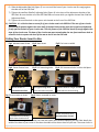
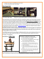
7) Lift the machine on the opposite end to allow the legs to fold down and rest against the leg stops
(Figure 1b)
8) Insert the Leg Lock Pins into the leg supports located on both sides of the legs (figure 1b)
9) Tighten the Leg Lock located on the side of the SRG-50 (figure 1b)
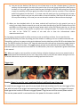
10) Install the wheels on the axles located on the left and right sides of the SRG-50. Place an inner ½”
washer on the wheel axle, slide the wheel onto the wheel axle, place an outer ½” washer against the
wheel and install the cotter pin in the 1/8” hole of the wheel axle. Using a pair of plyers, bend both
sides of the cotter pin over the axle.
Checking Calibration
Your SRG-50 has been calibrated and tested at our facility but it is advisable to recheck calibration to be sure
the calibration did not come out of adjustment during shipping.
There are three calibration adjustment points on the SRG-50.
a) The side fence squaring adjustment
b) The side fence swivel bolt
c) Roller guide adjustment
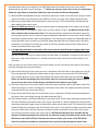
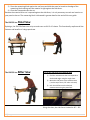
Side Fence Squaring Adjustment:
Figure 2
1) The side fence comes pre-squared from our facility but you should check for square by holding a 2 foot
square against the cut rail (top clamp) and the side fence. If squaring is required, loosen the Jam Nut
(figure 2) on the Side Fence Calibration Bolt (figure 2) and adjust the Calibration Bolt as necessary.
Tighten the Jam Nut on the Calibration Bolt and re-check for square.
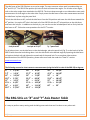
2) Side Fence Swivel bolt:
The side fence has been adjusted at our facility but it is a good practice to check the adjustment from
time to time. The side fence should have very little play in a rocking motion therefore some resistance
in movement is normal when moving out of the 90 degree position. If there is excessive rocking back
3|Page