1
I-7243D
MODBUS TCP Server/DeviceNet Master
Gateway
User’s Manual
Warranty
All products manufactured by ICP DAS are under warranty
regarding defective materials for a period of one year from the date of
delivery to the original purchaser.
Warning
ICP DAS assumes no liability for damages resulting from the use
of this product. ICP DAS reserves the right to change this manual at
any time without notice. The information furnished by ICP DAS is
believed to be accurate and reliable. However, no responsibility is
assumed by ICP DAS for its use, or for any infringements of patents or
other rights of third parties resulting from its use.
Copyright
Copyright 2006 ~ 2007 by ICP DAS. All rights are reserved.
Trademark
The names used for identification only may be registered
trademarks of their respective companies.
I-7243D MODBUS TCP/DeviceNet Gateway User’s Manual (Version 1.0, April/2007)
1
Table of Contents
1.
General Information ......................................................................5
1.1
DeviceNet Introduction ....................................................................................... 5
1.2
DeviceNet Applications........................................................................................ 7
1.3
Module Characteristics ....................................................................................... 8
1.4
Hardware and Firmware Features..................................................................... 9
1.5
Specifications ...................................................................................................... 10
1.6
Typical Applications .......................................................................................... 12
1.6.1
Modbus/TCP to multi-Modbus/RTU converter........................................... 12
1.6.2
Protocol converter with VxComm technology ............................................ 13
1.6.3
Modbus/TCP to DeviceNet gateway ........................................................... 15
2.
Hardware.......................................................................................19
2.1
Pin Assignment................................................................................................... 19
2.1.1
RS-232 & RS-485 & Power supply interface .............................................. 20
2.1.2
Connect to DeviceNet devices ..................................................................... 21
2.1.3
Ethernet connection ..................................................................................... 22
2.2
Terminator resistor settings.............................................................................. 23
2.3
LED Indication................................................................................................... 25
2.3.1
Power LED................................................................................................... 25
2.3.2
Module Status indicator LED ...................................................................... 26
2.3.3
5-digits 7-Segment LED Displays ............................................................... 28
3.
DeviceNet Interface ......................................................................31
3.1
Network Communication .................................................................................. 31
3.2
Slave Device Communication............................................................................ 31
3.3
Scan Cycles ......................................................................................................... 31
3.4
Interaction with Internal Memory ................................................................... 32
4.
Modbus/TCP Interface ................................................................33
4.1
Commands .......................................................................................................... 33
4.2
Exception Codes ................................................................................................. 33
4.3
Modbus/TCP Addressing .................................................................................. 34
I-7243D MODBUS TCP/DeviceNet Gateway User’s Manual (Version 1.0, April/2007)
2
4.3.1
4.3.2
4.3.3
4.3.4
5.
Input/Output Data Areas .............................................................................. 35
Command Area ............................................................................................ 37
Output Status Area....................................................................................... 38
Input Status Area.......................................................................................... 39
Configuration ................................................................................46
5.1
I-7243D Configuration Tool ( I-7243D Utility ) .............................................. 46
5.1.1
Install & uninstall the I-7243D Utility......................................................... 47
5.1.2
How to set/connect with the module............................................................ 53
5.1.3
How to configure the module’s DeviceNet MACID and Baud rate............ 55
5.1.4
How to configure the module’s application mode....................................... 57
5.1.5
How to add/remove/configure DeviceNet devices ...................................... 61
5.1.6
How to start/stop to communicate with DeviceNet devices ........................ 65
5.1.7
How to get the configuration/status of each DeviceNet device................... 67
5.1.8
6.
How to get the I/O data of each DeviceNet device...................................... 69
5.2
MBRTU Tool...................................................................................................... 75
5.3
MBTCP Tool ...................................................................................................... 76
Specific Data Formats ..................................................................77
6.1
Commands For Configuring DeviceNet Devices............................................. 79
6.1.1
DNM_Reset ................................................................................................. 79
6.1.2
DNM_SetMasterMACID............................................................................. 80
6.1.3
DNM_SetBaudRate ..................................................................................... 81
6.1.4
DNM_AddDevice ........................................................................................ 82
6.1.5
DNM_RemoveDevice.................................................................................. 83
6.1.6
DNM_RemoveIOConnection ...................................................................... 84
6.1.7
DNM_ConfigBitStrobe................................................................................ 85
6.1.8
DNM_ConfigPoll......................................................................................... 86
6.1.9
6.1.10
6.1.11
6.1.12
6.1.13
6.1.14
6.1.15
6.1.16
6.1.17
6.1.18
DNM_ConfigCOS ....................................................................................... 87
DNM_ConfigCyclic..................................................................................... 88
DNM_StartDevice ....................................................................................... 89
DNM_StopDevice........................................................................................ 90
DNM_StartAllDevice .................................................................................. 91
DNM_StopAllDevice .................................................................................. 92
DNM_ClearAllConfig ................................................................................. 93
DNM_UpdateBitStrobeConfig .................................................................... 94
DNM_UpdatePollConfig ............................................................................. 95
DNM_UpdateCOSConfig............................................................................ 96
I-7243D MODBUS TCP/DeviceNet Gateway User’s Manual (Version 1.0, April/2007)
3
6.1.19
DNM_UpdateCyclicConfig ......................................................................... 97
6.2
Commands For Configuring Input/Output Data Area .................................. 98
6.2.1
Set_Input_Data_Area................................................................................... 98
6.2.2
Set_Output_Data_Area .............................................................................. 100
6.2.3
Clear_All_Input_Data_Area ...................................................................... 102
6.2.4
Clear_All_Output_Data_Area ................................................................... 103
6.3
7.
The Communicated Flow Diagram ................................................................ 104
VxComm Applications ...............................................................105
7.1
Overview ........................................................................................................... 105
7.1.1
Architecture................................................................................................ 106
7.1.2
Ports mapping ............................................................................................ 107
7.2
Installing the VxComm Driver ....................................................................... 108
7.3
Adding an I-7243D and configuring the VxComm Driver........................... 109
7.4
Removing an I-7243D ...................................................................................... 115
7.5
Uninstalling the VxComm Driver................................................................... 117
8.
Diagnostics and Troubleshooting..............................................119
8.1
Diagnostics ........................................................................................................ 119
8.2
Troubleshooting ............................................................................................... 122
Appendix A:
Connection Status Table...........................................126
Appendix B:
Command Table ........................................................128
Appendix C:
Result Table ...............................................................130
I-7243D MODBUS TCP/DeviceNet Gateway User’s Manual (Version 1.0, April/2007)
4
1.
General Information
1.1
DeviceNet Introduction
The CAN (Controller Area Network) is a serial communication protocol, which
efficiently supports distributed real-time control with a very high level of security. It
is an especially suited for networking "intelligent" devices as well as sensors and
actuators within a system or sub-system. In CAN networks, there is no addressing
of subscribers or stations in the conventional sense, but instead, prioritized
messages are transmitted. DeviceNet is one kind of the network protocols based
on the CAN bus and mainly used for machine control network, such as textile
machinery, printing machines, injection molding machinery, or packaging
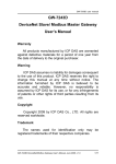
machines, etc. DeviceNet is a low level network that provides connections
between simple industrial devices (sensors, actuators) and higher-level devices
(controllers), as shown in Figure 1.1.
Figure 1.1 Example of the DeviceNet network
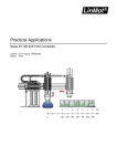
DeviceNet is a cost effective solution to one kind application of control
c\area network. It reduces the connection wires between devices and provides
rapid troubleshooting rejection function. The transfer rate can be up to 500Kbps
within 100 meters. The transfer distance can be up to 500 meters in 125Kbps
(See Table 1.1). It allows direct peer to peer data exchange between nodes in an
organized and, if necessary, deterministic manner. Master/Slave connection
model can be supported in the same network. Therefore, DeviceNet is able to
facilitate all application communications based on a redefine a connection
scheme. However, DeviceNet connection object strands as the communication
I-7243D MODBUS TCP/DeviceNet Gateway User’s Manual (Version 1.0, April/2007)
5
path between multiple endpoints, which are application objects that is needed to
share data.
Baud rate (bit/s)
Max. Bus length (m)
500 K
100
250 K
250
125 K
500
Table 1.1 The Baud rate and the Bus length
I-7243D MODBUS TCP/DeviceNet Gateway User’s Manual (Version 1.0, April/2007)
6
1.2
DeviceNet Applications
DeviceNet is the standardized network application layer optimized for
factory automation. It is mainly used in low- and mid-volume automation systems.
Some users have also implemented DeviceNet for machine control systems. The
main DeviceNet application fields include the following application area (For
more information, please refer to www.odva.org):
● Production cell builds and tests CPUs
● Dinnerware production
● Beer brewery
● HVAC module production
● Equipment for food packing
● Textile machines
● Fiberglass twist machine
● Trawler automation system
● Sponge production plant
● LCD manufacturing plant
● Isolation wall manufacturing
● Rolling steel door production
● Overhead storage bin production
● Bottling line
● Pocket-bread bakery
● Tight manufacturing
I-7243D MODBUS TCP/DeviceNet Gateway User’s Manual (Version 1.0, April/2007)
7
1.3
Module Characteristics
“Embedded Internet” and “Embedded Ethernet” are hot topics today.
Nowadays the Ethernet protocol becomes the de-facto standard for local area
network. Via Internet, connectivity is occurring everywhere, from home appliances
to vending machines to testing equipment to UPS…etc. Using Ethernet for network
in industrial area is appealing because the required cabling is already installed.
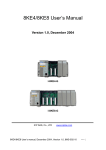
The I-7243D from ICP DAS is a solution that provides a communication
protocol transfer the DeviceNet to Modbus/TCP protocol and solves a
mission-critical problem: connecting an existing DeviceNet network to
Ethernet-base PLCs and PC-based configuration and monitor system. It enables
DeviceNet networks to be coupled together over the Internet/Ethernet, whereby
remote monitoring and control is possible.
The I-7243D can be a DeviceNet master device in the CAN bus on the
DeviceNet network. It provides “Predefined Master Connection Set”, and supports
Group 2 only Server functions to communication with slave devices. On the
Ethernet network, it acts as a Modbus TCP server. Users can use Modbus TCP
class 0, class 1 and partial class 2 function to communicate with it. In addition, we
also provide Utility software for users to configure their device parameters for the
I-7243D. The following figure shows the application architecture for the I-7243D.
Figure 1-2:
Application of I-7243D
I-7243D MODBUS TCP/DeviceNet Gateway User’s Manual (Version 1.0, April/2007)
8
1.4
Hardware and Firmware Features
Hardware Features
z
z
z
z
z
z
z
z
z
z
z
80186, 80MHz CPU, or compatible
Philip SJA1000 CAN controller with 16M Hz clock
Phillip 82C250 CAN Transceiver
1K VDC isolation on CAN side.
Support both CAN specification 2.0A and 2.0B.
Jumper select 120Ω terminator resistor for CAN channel
10/100 BASE-T DM9000AE compatible Ethernet Controller
Support one RS-232 port, one RS-485 port and one CAN port
Built-in self-tuner ASIC controller on RS-485 port
7-segment LED display.
MS LED , NS LED , RUN LED
Firmware Features
z
z
z
z
z
z
z
z
z
z
z
z
Programmable DeviceNet Master MAC ID.
Programmable DeviceNet transfer-rate 125K, 250K, 500K.
Supports maximum DeviceNet devices up to 63
Predefined Master/Slave Connection Set
The maximum Fragment number is (Input/Output) up to 64
Supports I/O Operation Mode: Poll, Bit-Strobe and Change Of State/Cyclic
Supports one Poll, one Bit-Strobe, one COS, one Cyclic IO connection for
each DeviceNet device when connected with this module.
Supports on-line adding device into and removing device from DeviceNet
network.
Supports boot-up auto communicate with slave devices.
Converters single Mobbus/TCP to multi Modbus/RTU, set by Utility
Supports VxComm technique for every COM ports of I-7243D, set by Utility
Allowed multi-Modbus TCP clients access simultaneously
I-7243D MODBUS TCP/DeviceNet Gateway User’s Manual (Version 1.0, April/2007)
9
1.5
Specifications
RS-232 specification:
z RS-232 interface connector: TXD, RXD, CTS, RTS, GND;
z RS-232 Baud Rate: 110, 150, 300, 600, 1200, 2400, 4800, 9600, 19200,
38400, 57600, 115200 bps;
RS-485 specification:
z RS-485 interface connector: D2+, D2-;
z Self-turn ASIC inside;
Ethernet specification:
z 10/100 Base-T
CAN specification:
z CAN signal support: CAN_H, CAN_L;
z CAN bus interface: ISO 11898-2 ; 5 pin screw terminal connector.
z Isolation voltage: 1K VDC isolation on the CAN side;
Power requirement:
z Unregulated +10V DC ~ +30V DC;
z Power reverse protection, Over-Voltage brown-out protection;
z Power consumption: 3W;
Module specification:
z Dimensions: 123mm x 64.5mm x 19.6mm;
z Operating temperature: -25 to 75ºC;
z Storage temperature: -40 to 80ºC;
z
z
Humidity: 5 to 95%, non-condensing;
LEDs: Power led, MS, NS, RUN, 5-digits 7 segment led displays
I-7243D MODBUS TCP/DeviceNet Gateway User’s Manual (Version 1.0, April/2007)
10
Software Utility tool:
z
z
z
z
z
z
Online adding/removing DeviceNet devices via Ethernet
Online monitoring and configuring devices status via Ethernet.
Get/Set Modbus/TCP input/output memory address
Support DeviceNet I/O mapping table.
Show DeviceNet devices connection status.
Support communication modes setting.
Application:
z
z
z
z
z
z
Factory Automation;
Building Automation;
Home Automation;
Control system;
Monitor system;
Vehicle Automation;
I-7243D MODBUS TCP/DeviceNet Gateway User’s Manual (Version 1.0, April/2007)
11
1.6
Typical Applications
Although the I-7243D is designed as a Modbus/TCP server to DeviceNet
master Gateway. But it can be used to link these RS-232/RS-485/DeviceNet
devices to central computer as follows:
1.6.1
Modbus/TCP to multi-Modbus/RTU converter
I-7243D can be a single Modbus/TCP to multi-Modbus/RTU converter. You
can simple use the I-7243D Utility software to configure the device and then set
connection between SCADA, HMI software and the I-7243D. The block diagram of
this application of I-7243D is given as follows:
Figure 1-3:
MBTCP to MBRTU application of I-7243D
I-7243D MODBUS TCP/DeviceNet Gateway User’s Manual (Version 1.0, April/2007)
12
1.6.2
Protocol converter with VxComm technology
An I-7243D can also be able to link to serial devices that don’t support
Modbus/RTU. To use this function, you will need to install VxComm driver on host
PCs. After installation, you will be able to access the remote COM ports via the
standard serial driver.
Figure 1-4:
VxComm Application_1 of I-7243D
Compared to the RS-485 network, these Ethernet network hubs are already in
existence for system network. Therefore, the RS-232 devices can find the closest
hub and link to the central computer with the help of the I-7243D. The Ethernet
network is extremely popular and already existing for most applications, hence, this
approach is a very successful. In general, it is more difficult to write a TCP/IP
program than a COM 1/2 program. Therefore, the VxComm technology is
developed to simulate COM-ports of the I-7243D to become COM 3/4/5…/256
of the central computer. Then users can write a COM port program to link these
RS-232/RS-485 devices and need not to concern themselves with any TCP/IP
problem.
I-7243D MODBUS TCP/DeviceNet Gateway User’s Manual (Version 1.0, April/2007)
13
In some factories, there are old systems still running and in case. These old
systems only support COM port applications. Therefore, the Vxcomm technology
can be used to upgrade these old systems to support Ethernet network.
To recap, the VxComm technology is useful as follows:
z Provides a much easier interface for software programmers.
z Keeps the old systems going without program modification
The block diagram of VxComm technology for the I-7243D is given as follows:
Figure 1-5:
VxComm Application_2 of I-7243D
The VxComm technology can be used to simulate COM ports of the I-7243D to
become a COM port of PC. With the help of VxComm driver, users can access the
remote COM ports of the I-7243D just as them would access the PC’s COM port.
I-7243D MODBUS TCP/DeviceNet Gateway User’s Manual (Version 1.0, April/2007)
14
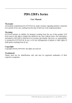
1.6.3
Modbus/TCP to DeviceNet gateway
The I-7243D provides centralized data storage, “Internal Memory”, for data
that is shared between the DeviceNet and Modbus/TCP network. Data is placed
into the “Internal Memory” by one network interface, allowing the data to be
read/wrote through the other network interface.
Figure 1-6:
Internal Memory Table of I-7243D
I-7243D MODBUS TCP/DeviceNet Gateway User’s Manual (Version 1.0, April/2007)
15
ICP DAS DeviceNet Master Module (I-7243D) provides users to establish
DeviceNet network rapidly by Master/Slave connection model. The DeviceNet
Module acts as a Modbus/TCP server to DeviceNet master gateway. Using the
module, users don’t need to take care of the detail of the DeviceNet protocol.
The module will implement the DeviceNet protocol automatically. It can reduce
the complexity of user’s DeviceNet Master Software. The module mainly
supports the Predefined Master/Slave Connection Set functions to allow users to
merge I/O data into DeviceNet network by using Modbus/TCP commands. It can
help users to establish the connection with DeviceNet slave devices easily. The
general application architecture is demonstrated as Figure 1.7.
Figure 1-7:
MBTCP to DeviceNet application of I-7243D
I-7243D MODBUS TCP/DeviceNet Gateway User’s Manual (Version 1.0, April/2007)
16
The module only provides the DeviceNet Master mechanism to
communicate with slave devices by the Predefined Master/Slave Connection Set,
which can be clarify as two forms: One is the Explicit Message and others are I/O
Messages. Note that before communicating I/O data with DeviceNet slave
devices, the Master device must connect to slave devices by explicit message
connection to define the connection object. Here, we only provide one explicit
message connection and four I/O connections as depicted in Figure 1.8.
Figure 1-8:
DeviceNet Messaging
The DeviceNet Communication Protocol is based on the concept of
connections method. Master should create connections with slave devices based
on the command of exchanging information and I/O data. To establish master
control mechanism, there are only four main steps to be followed. Figure 1.9
demonstrates the basic process for the DeviceNet master communication. The
every step function is described in below:
Figure 1-9:
Four steps to establish connection
I-7243D MODBUS TCP/DeviceNet Gateway User’s Manual (Version 1.0, April/2007)
17
1. Add device into network
You should provide the slave device’s MAC ID to add into network.
2. Configure connection
You can check the slave device’s I/O connection type and the I/O data length.
When configuring the I/O connection, you should provide these parameters.
3. Establish connection
After configuring connections, users can start communicating with slave
devices.
4. Access I/O data
After communicating with slave devices, you can access the I/O data with
corresponding read/write function.
After establishing the explicit connection, the connection path is then used
to exchange the general information from one node to the others. And then users
can create the I/O connections in the next step. Once I/O connections have been
created, I/O data may be exchanged among devices in the DeviceNet network
according to master device demand. Therefore, the master device can access
I/O data of the slave devices by one of the four I/O connection methods. The
module is not only easy to use but also providing a lot of the Modbus/TCP
commands to retrieve and deliver the slave’s I/O data. For more information,
please refer to command description in section 6.
I-7243D MODBUS TCP/DeviceNet Gateway User’s Manual (Version 1.0, April/2007)
18
2.
Hardware
2.1
Pin Assignment
CAN Bus
Connector
Bypass CAN
Bus Connector
DeviceNet
Status LED
Power LED
7-segment
LED displays
Power Input
Ethernet 10/100
Base T
RS-485 Port
RS-232 Port
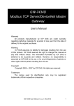
Figure 2-1:
INIT * pin
Pin assignment on the I-7243D
I-7243D MODBUS TCP/DeviceNet Gateway User’s Manual (Version 1.0, April/2007)
19
2.1.1
RS-232 & RS-485 & Power supply interface
The I-7243D provides one RS-232 interface and one RS-485 interface with
hardware flow control. The GND-signal of COM1 is shared with pin-9, GND. The pin
assignment is shown in table 2-1.
Pin
Name
Description
1
CTS1
2
RTS1
CTS pin of COM1 (RS-232)
RTS pin of COM1 (RS-232)
3
RXD1
RXD pin of COM1 (RS-232)
4
TXD1
TXD pin of COM1 (RS-232)
5
INIT*
Initial pin for enable/disable
AUTOEXEC.BAT
6
D2+
Data+ pin of COM2 (RS-485)
7
D2-
Data- pin of COM2 (RS-485)
8
Vs+
V+ of power supply
(+10V to +30V DC unregulated)
9
GND
GND of power supply
Table 2-1: COM Connector Pin Assignment
I-7243D MODBUS TCP/DeviceNet Gateway User’s Manual (Version 1.0, April/2007)
20
2.1.2
Connect to DeviceNet devices
In order to provide an easy CAN bus wiring, the I-7243D supplies one CAN port
with two CAN bus connector interfaces. Each connecter built on the I-7243D looks
like as figure 2-3 and table 2-2.
Pin No.
Signal
Description
1
N/A
Unavailable
2
CAN_L
CAN_L bus line (dominant low)
3
N/A
Unavailable
4
CAN_H
CAN_H bus line (dominant high)
5
N/A
Unavailable
Table 2-2: CAN bus Connector Pin Assignment
Note that the bypass CAN bus connector is not another CAN channel. It is
designed for connecting to another CAN device conveniently. The structure of the
inside electronic circuit is displayed as figure 2-2.
Figure 2-2 Electronic circuit of CAN bus connector
I-7243D MODBUS TCP/DeviceNet Gateway User’s Manual (Version 1.0, April/2007)
21
2.1.3
Ethernet connection
The Ethernet (10/100 Base-T) signals are routed to an RJ45 socket for easy
connection using a standard CAT 3 or CAT 5 network cable. On power on of the
I-7243D, it will auto-negotiate the network speed and connection.
Pin
Name
Description
1
TX+
Transmit Data +
2
TX-
Transmit Data -
3
RX+
Receive Data +
4
N.C.
Not Connected
5
N.C.
Not Connected
6
RX-
Receive Data -
7
N.C.
Not Connected
8
N.C.
Not Connected
Table 2-3: Ethernet Connector Pin Assignment
I-7243D MODBUS TCP/DeviceNet Gateway User’s Manual (Version 1.0, April/2007)
22
2.2
Terminator resistor settings
In order to minimize reflection effects on the CAN bus line, the CAN bus lines
have to be terminated at both ends by two terminal resistances. Based on the ISO
11898-2 spec, each terminal resistance is 120Ω (or between 108Ω~132Ω). The
length related resistance should have 70 mΩ/m. Users should check the
resistances of their CAN bus, before they install a new CAN network as figure 2-3.
Figure 2-3: Terminator resistor
Moreover, to minimize the voltage drop on long distance, the terminal
resistance should be higher than the value defined in the ISO 11898-2. Table 2-4
may be used as a reference.
Bus
Length
(meter)
Bus Cable Parameters
Terminal
Resistance
(Ω)
Length Related
Resistance
(mΩ/m)
Cross Section
(Type)
0~40
70
0.25(23AWG)~
0.34mm2(22AWG)
124 (0.1%)
40~300
< 60
0.34(22AWG)~
0.6mm2(20AWG)
127 (0.1%)
< 40
0.5~0.6mm2
(20AWG)
150~300
< 20
0.75~0.8mm2
(18AWG)
150~300
300~600
600~1K
Table 2-4: Relation between bus cable and length
I-7243D MODBUS TCP/DeviceNet Gateway User’s Manual (Version 1.0, April/2007)
23
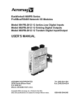
Therefore, the I-7243D module supplies a jumper for users to connect the
terminator resistor or not. If users want to use this terminator resistor, please open
the I-7243D cover and use the JP3 jumper to activate the 120Ω terminator resistor
built in the system, as in the figure 2-4. Note that the default setting is active. And
about the J3 jumper setting, please refer the table 2-5.
Figure 2-4
XC100 I/O expansion board LAYOUT
Apply the termination
resistor(120Ω)
Don’t apply the termination
resistor
Table 2-5 J3 Jumper Selection
I-7243D MODBUS TCP/DeviceNet Gateway User’s Manual (Version 1.0, April/2007)
24
2.3
LED Indication
The I-7243D acts as a Modbus/TCP to DeviceNet gateway. It provides some
LEDs to indicate what situation the I-7243D is in.
2.3.1
Power LED
There is a red indicator-LED in the I-7243D as follow:
Firmware is running: flashing red
The default shipping of I-7243D will be firmware inside, so the red
indicator-LED of I-7243D will be flashing two times per second periodically.
I-7243D MODBUS TCP/DeviceNet Gateway User’s Manual (Version 1.0, April/2007)
25
2.3.2
Module Status indicator LED
The I-7243D includes three single-color LED displays to indicate the status of
module, network and I/O device. They are MS LED (it is red), NS LED (it is green),
and RUN LED (it is red). The Indicators assist maintenance personnel in quickly
identifying a problem unit. When the I-7243D events occur, these indicators will be
triggered to glitter with different conditions.
z MS LED
This led provides module status and indicates whether or not the module is
operating properly. Table 2-6 shows the conditions of MS status. Therefore, when
the I-7243D is operated normally, the MS led must be turned off.
Condition
Description
Off
Module is normal; no error occurs
Red
Module has unrecoverable fault
Flashing red Module has recoverable fault.
To recover:
Reset device or perform error recovery
Table 2-6 MS led conditions
z NS LED
This led indicates the DeviceNet communication status of the module. Table 2-7
shows the conditions of NS status. When module is online and start to
communicate with the devices, it will be solid green. If there are some devices
disconnected with the I-7243D, the NS led will be flashing.
Condition
Description
off
Module stops to communicate with all devices
Flashing green
Solid green
There exists at least one device disconnect with
the module
Module is online and start to communicate with
all devices
Table 2-7 NS led conditions
I-7243D MODBUS TCP/DeviceNet Gateway User’s Manual (Version 1.0, April/2007)
26
z RUN LED
This led indicates the configuration status of the I-7243D. Table 2-8 shows the
conditions for RUN status. If there is no configuration, the RUN led will be flashing.
After configuring the DeviceNet devices by I-7243D Utility tool, the I-7243D will start
to communicate with them and the RUN led will becomes solid red.
Condition
Description
Off
Some errors occur on the module
Flashing red
Module is waiting for configuring
Solid red
Module has been configured O.K.
Table 2-8 RUN led conditions
I-7243D MODBUS TCP/DeviceNet Gateway User’s Manual (Version 1.0, April/2007)
27
2.3.3
5-digits 7-Segment LED Displays
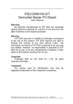
The 5-digits 7-SEG LED will show as figure 2-5.
Figure 2-5
7-SEG LED Displays
The important information of I-7243D can be divided as follows:
z Group-ID 11111: IP information of this I-7243D
z Group-ID 22222: baud rate of all ports
z Group-ID 33333: configuration of all ports
z Group-ID 44444: client-connected information and system reset state of this
I-7243D
The IP information format of I-7243D is given as follows:
z Group-ID of 5-digit LED: 11111.
z LED-1: indicator, can be 1 or 2 or 3 or 4
z LED-2~5: IP
The LED will show Group-ID first, and then show its IP as the above diagram
indicates. If users change IP, the value shown will change immediately. The default
I-7243D MODBUS TCP/DeviceNet Gateway User’s Manual (Version 1.0, April/2007)
28
shipping IP = 192.168.255.1 Î the LED-show sequence is given as above
diagram.
The baud-rate format of COM ports are given as follows:
z Group-ID of 5-digit LED: 22222.
z LED-1: COM port number
z LED-2~5: value of (baud/100)
The baud-rate format of CAN port is given as follows:
z LED-1: indicator, 3, CAN port.
z LED-2~5: value of (baud/1000)
The COM port are shown in LED-1 and their baud rate is shown in the
LED-2~5. The COM port baud rate = (value of LED-2~5)*100. Therefore,
shown-value=1. 96 means baud rate of COM1=9600BPS; shown-value= 2.1152
means baud rate of COM2= 115200 BPS. It’s the same as the CAN port baud rate.
The CAN port baud rate = (value of LED-2~5)*1000. Therefore, shown-value=3.
125 means baud rate of DeviceNet network =125KBPS; shown-value= 3.500
means baud rate of DeviceNet network= 500KBPS. All baud rate of I-7243D’s port
will be shown one by one.
The configuration of COM ports are given as follows:
z Group-ID of 5-digit LED: 33333.
z LED-1: COM port number
z LED-3: data bit, 7 or 8
z LED-4: parity bit, 0=no parity, 1=even parity, 2=odd parity
z LED-5: stop bit, 1 or 2
The configuration of CAN port is given as follows:
z LED-2/3: fix string, “id.”.
z LED-4/5: DeviceNet MAC ID of this module, default 00.
The connection-client information is given as follows:
z Group-ID of 5-digit LED: 44444.
z LED-2/3: numbers of free sockets are available, default 25.
z LED-4/5: numbers of sockets are used by clients, default 0.
I-7243D MODBUS TCP/DeviceNet Gateway User’s Manual (Version 1.0, April/2007)
29
The reset state of system is given as follows:
z LED-2~5: reset number, display in decimal mode.
When the I-7243D is powered-off or just been reset, the reset number will be
increased. If any one client connects to this I-7243D, the free-sockets will be
decreased and used-sockets will be increased. If the free-sockets number is
reduced to 0, then no extra client can link to this I-7243D. The default number of
free-sockets is 25. Therefore, the I-7243D allows 25 clients link to it.
I-7243D MODBUS TCP/DeviceNet Gateway User’s Manual (Version 1.0, April/2007)
30
3.
DeviceNet Interface
3.1
Network Communication
The I-7243D, Modbus/TCP to DeviceNet Gateway, acts as a DeviceNet master
on DeviceNet network. It can exchange I/O data with up to 63 nodes. Users can use
the I-7243D Utility tool to access the module over Ethernet network via
Modbus/TCP commands.
3.2
Slave Device Communication
After the configuration of slave devices, the I-7243D will start to establish
connections with device in the scan list (list of configured slaves). Once connections
are established, the module will perform all necessary steps to configure the
required I/O messaging.
The I-7243D provides explicit message proxy services for all “Group 2 Only
Server” devices. Once any Group 2 Only devices are configured, the I-7243D will
send message to the devices, explicit message connection value for
watchdog_timeout_action to “Deferred Delete”, in addition to the I/O messages.
This function prevents the explicit message connections between the I-7243D and
the slave from timing out when communicating with I/O messages.
The I-7243D supports four I/O messaging types specified by the DeviceNet
protocol. These include polling, bit-strobe, COS, Cyclic I/O messages. I/O
messaging and I/O parameters are configured by using the I-7243D Utility tool.
3.3
Scan Cycles
The I-7243D employs a scan cycle for producing I/O messages. A scan cyclic
consists of the following:
z Polling messages to every device configured as polled I/O
z Bit-Strobe output messages to devices configured as bit-strobe.
If the internal timer exceeds the explicit packet rate of certain I/O connections, the
I/O message will be sent to the slave devices.
I-7243D MODBUS TCP/DeviceNet Gateway User’s Manual (Version 1.0, April/2007)
31
3.4
Interaction with Internal Memory
The DeviceNet interface in the I-7243D accesses the I/O data areas from slave
I/O connections processed by the DeviceNet master; there is no synchronization
between the Ethernet and DeviceNet network interfaces. As shown in the following
picture.
When an I/O connection with a slave requires that output data be sent to the
slave, it will be read from the Output Data Area. The data read is what was placed
there by the last write to the Output Data Area by using Modbus/TCP commands.
When input data is received from DeviceNet I/O connection, it is copied to the
Input Data Area. This data is available to be read by the Modbus/TCP commands
on the next data exchange.
All the connection status and configuration are stored in the Status Area of
I-7243D’s Internal Memory. And these data are available to be read by the
Modbus/TCP commands at any time.
The Command Area is used for saving Modbus/TCP commands that contain
specific data formats packed in the “Force Multiple Registers” command, function
code: 16. After receiving this specific data format command, the I-7243D will
unscramble it and perform the relative procedure.
I-7243D MODBUS TCP/DeviceNet Gateway User’s Manual (Version 1.0, April/2007)
32
4.
Modbus/TCP Interface
The I-7243D supports Modbus/TCP commands. The implementation of the
Modbus/TCP server is done according to the Modbus/TCP specification 1.0. All
commands according to class 0, class 1 and partially class 2 slave functionality are
implemented.
The module can handle maximum 25 simultaneous Modbus TCP connections.
4.1
Commands
The following Modbus/TCP commands are supported by the I-7243D.
Function Code
Function Name
Class Affects Address Method
1
Read Coils
1
IN/OUT
Bit
2
Read Input Discrete
1
IN/OUT
Bit
3
Read Multiple Registers
0
IN/OUT
Word
4
Read Input Registers
1
IN/OUT
Word
5
Write Coil
1
OUT
Bit
6
Write Single Register
1
OUT
Word
15
Force Multiple Coils
2
OUT
Bit
16
Force Multiple Registers
0
OUT
Word
Table 4-1: Modbus Commands
4.2
Exception Codes
An exception code is returned in the response when the I-7243D is unable to
service the Modbus request that was received. The following exception codes will
be used by the I-7243D.
Exception Code
Name
Description
01
Illegal Function
The module does not support the
function code in the query
02
Illegal Data address
The data received in the query is
outside the initialized memory area
03
Illegal Data Value
The data in the request is illegal
Table 4-2: Exception Codes
I-7243D MODBUS TCP/DeviceNet Gateway User’s Manual (Version 1.0, April/2007)
33
4.3
Modbus/TCP Addressing
The I-7243D supports an “Internal Memory” for saving I/O data. The input and
output data areas are set to a maximum size of 256 words each. The command
area is 255 words. The input status area is 4642 words and the output status area is
322 words. When accessing these areas, by Modbus commands, the address is
according to the following tables.
I-7243D MODBUS TCP/DeviceNet Gateway User’s Manual (Version 1.0, April/2007)
34
4.3.1
Input/Output Data Areas
The I/O Data Area are used for users to access devices I/O data directly. After
using Utility tool to set the memory mapping of the I/O devices, users can get/set
the I/O data according to the mapping address of each I/O data.
Users can use Modubs FC4 command, read input registers, to get the input
data values from I-7243D’s input data area.
Word Address (3xxxx)
0000h
0001h
0002h
:
00FFh
Table 4-3: Input Addressing
Users can use Modbus FC16 command, force multiple registers, to set the
output data values into I-7243D’s output data area.
Word Address (4xxxx)
0000h
0001h
0002h
:
00FFh
Table 4-4: Output Addressing
I-7243D MODBUS TCP/DeviceNet Gateway User’s Manual (Version 1.0, April/2007)
35
I/O Data Format
The I-7243D transfers I/O data between Modbus/TCP and DeviceNet without
regard to data content or format. Due to this, the user is responsible for making sure
that the devices on either network understand the format of the data.
DeviceNet is a little-endian protocol; values ate transmitted least significant
byte first. Therefore, all data in the I/O Data Areas is assumed, by DeviceNet nodes,
to be stored as little-endian.
Users should to make sure the Modbus/TCP master handles input data and
transmits output data in a format acceptable to the target DeviceNet devices (least
significant byte first). The user must know where in the I/O Data Areas DeviceNet
data has been mapped.
I-7243D MODBUS TCP/DeviceNet Gateway User’s Manual (Version 1.0, April/2007)
36
4.3.2
Command Area
The Command Area is used for saving Modbus/TCP commands that contain
specific data formats packed in the “Force Multiple Registers” command, function
code: 16. After receiving this specific data format command, the I-7243D will
unscramble it and perform the relative procedure.
Users can use Modubs FC16 command, force multiple registers, to send
specific data format into I-7243D’s command area. These specific data format types,
can be accepted by I-7243D, are listed and described in the section 6.
Word Address (4xxxx)
0100h
0101h
0102h
:
01FFh
Table 4-5: Command Addressing
I-7243D MODBUS TCP/DeviceNet Gateway User’s Manual (Version 1.0, April/2007)
37
4.3.3
Output Status Area
The Output Status Area is used for saving information for DeviceNet output
devices. Users can use Modubs FC3 command, read multiple registers, to read the
data from I-7243D’s Output Status Area.
Word Address (4xxxx)
Description
02FFh
Total number of output commands
0300h
0301h
:
Specific data format string for output command
061Fh
Table 4-6: Output Status Addressing
Word Address 02FFh: Total number of output commands.
If users use Utility tool to set the Internal Output Memory of output device, the
value of this parameter will be changed.
Word Address 0300h ~ 061Fh: Specific data format string.
For saving specific data format string that are sent by Utility tool to configure
output device data address. The types of the specific data format are described in
following table. Each specific data format contains 4 words. And the maximum
number of the command string is 100.
Word Address
(4xxxx)
Description
Data
Length
0300h
Device 1,
Start address of Output Data Area
2 Bytes
0x0000~0x01FF
0301h
Device 1, Output data length
2 Bytes
0x0000~0x0200
Device 1, MACID
1 Byte
0x00~0x3F
0302h(High)
0302h(Low)
Device 1,
Connection Type
1 Byte
Data
0x00: Explicit
0x01: Poll
0x02: Bit-Strobe
0x03: COS
0x04: Cyclic
0303h(High)
Device 1, Data Type
1 Byte
0x01: Output command
0303h(Low)
End Char = CR (0x0D)
1 Byte
0x0D
0304h~0307h
:
061Ch~061Fh
Device 2 data format
:
Device N data format
4 Words
:
4 Words
I-7243D MODBUS TCP/DeviceNet Gateway User’s Manual (Version 1.0, April/2007)
38
4.3.4
Input Status Area
The Input Status Area is used for saving information for each DeviceNet input
device. Users can use Modubs FC4 command, read input registers, to read the
data from I-7243D’s Input Status Area.
Word Address (3xxxx)
Description
02FFh
Total number of input commands
0300h
0301h
:
Specific data format string for input command
061Fh
0620h
:
Reserved
06EFh
06F0h
MAC ID & Baud-rate
06F1h
Firmware version
06F2h
Module status
06F3h
:
Reserved
06FFh
0700h
:
Scan-list table for each device
14BFh
14C0h
:
Reserved
14FFh
1500h
:
Allocate choice byte of each device
151Fh
Table 4-7: Input Status Addressing
Word Address 02FFh: Total number of input commands.
If users use Utility tool to set the Internal Input Memory of input device, the
value of this parameter will be increased or decreased.
I-7243D MODBUS TCP/DeviceNet Gateway User’s Manual (Version 1.0, April/2007)
39
Word Address 0300h ~ 0620h: Specific data format string.
For saving specific data format string that are sent by Utility tool to configure
input device data address. The type of the specific data format is described in the
following table. Each specific data format contains 4 words. And the maximum
number of the command string is 100.
Word Address
(3xxxx)
Description
Data
Length
Data
0300h
Device 1,
Start address of Input Data Area
2 Bytes
0x0000~0x01FF
0301h
Device 1,
Input data length
2 Bytes
0x0000~0x0200
0302h(High)
Device 1, MACID
1 Byte
0x00~0x3F
0x00: Explicit
0x01: Poll
0x02: Bit-Strobe
0x03: COS
0x04: Cyclic
0302h(Low)
Device 1,
Connection Type
1 Byte
0303h(High)
Device 1,
Data Type
1 Byte
0x00: Input command
0303h(Low)
End Char = CR (0x0D)
1 Byte
0x0D
0304h~0307h
:
061Ch~061Fh
Device 2 data format
:
Device N data format
4 Words
:
4 Words
Word Address 06F0h: DeviceNet MACID and baud-rate of I-7243D
High byte of word address 06F0h: DeviceNet MACID setting of I-7243D
Low byte of word address 06F0h: DeviceNet baud-rate setting of I-7243D
Word Address 06F1h: The firmware version of I-7243D
Word Address 06F2h: The status of I-7243D
The value of this word address can be 0(No Error), 1005(CAN Board Active
Error), 1600(Module Online Error), 2600(CAN Bus Error) decimal.
I-7243D MODBUS TCP/DeviceNet Gateway User’s Manual (Version 1.0, April/2007)
40
Word Address 0700h ~ 14C0h: Scan-list table for each device
The I-7243D supports 5 DeviceNet connection type, Explicit, Polling, Bit-Strobe,
COS, Cyclic connection, for each DeviceNet device. For each connection of every
device, there exist 14 parameters, 22 bytes, for users to understand what the status
the connection is. If there makes no connection with this connection, the values of
these parameters will be 0xFFh. The parameters of the scan-list are listed in the
below table.
Word Numbers
Byte Numbers
Description
1
Destination MACID
1
Connection Type
2
2
Input Data Length
3
2
Output Data Length
4
Start Time
1
Start Device Or Not
1
Connection Status
1
Command
1
Result
2
Explicit Packet Rate
1
Data In Status
1
Data Out Status
10
2
Data In Index
11
2
Data Out Index
1
4
5
6
7
8
9
Table 4-8: Parameters of Scan-list table
And the relative location of these parameters and connection are listed in the
following table.
Word Address (3xxxx)
0700h ~ 070Ah
(11 words)
070Bh ~ 0715h
(11 words)
0716h ~ 0720h
(11 words)
0721h ~ 072Bh
Description
Device MACID: 00
Explicit Connection
Parameters of Scan-list
Device MACID: 00
Poll Connection
Parameters of Scan-list
Device MACID: 00
Bit-Strobe Connection
Parameters of Scan-list
Device MACID: 00
I-7243D MODBUS TCP/DeviceNet Gateway User’s Manual (Version 1.0, April/2007)
41
(11 words)
072Ch ~ 0736h
(11 words)
0737h ~ 0741h
(11 words)
0742h ~ 074Ch
(11 words)
074Dh ~ 0757h
(11 words)
0758h ~ 0762h
(11 words)
0763h ~ 076Dh
(11 words)
COS Connection
Parameters of Scan-list
Device MACID: 00
Cyclic Connection
Parameters of Scan-list
Device MACID: 01
Explicit Connection
Parameters of Scan-list
Device MACID: 01
Poll Connection
Parameters of Scan-list
Device MACID: 01
Bit-Strobe Connection
Parameters of Scan-list
Device MACID: 01
COS Connection
Parameters of Scan-list
Device MACID: 01
Cyclic Connection
Parameters of Scan-list
076Eh ~ 07A4h
(55 words)
Device MACID: 02
Parameters of Scan-list
07A5h ~ 07DBh
(55 words)
Device MACID: 03
Parameters of Scan-list
07DCh ~ 07DBh
(55 words)
Device MACID: 04
Parameters of Scan-list
0813h ~ 0849h
(55 words)
Device MACID: 05
Parameters of Scan-list
:
:
:
:
141Bh ~ 1451h
(55 words)
Device MACID: 61
Parameters of Scan-list
1452h ~ 1488h
(55 words)
Device MACID: 62
Parameters of Scan-list
1489h ~ 14BFh
(55 words)
Device MACID: 63
Parameters of Scan-list
Table 4-9: Scan List Table for each device
I-7243D MODBUS TCP/DeviceNet Gateway User’s Manual (Version 1.0, April/2007)
42
Destination MACID: The destination device MACID of this connection, 0~63.
Connection Type:
The connection type of this connection.
Connection Type
values(decimal)
Explicit Connection
0
Poll Connection
1
Bit-Strobe Connection
2
COS Connection
3
Cyclic Connection
4
Input Data Length:
The input data length of the device that this connection
communicating with, displaying in decimal mode.
Output Data Length: The output data length of the device that this connection
communicating with, displaying in decimal mode.
Start Time: The start time of the module send a request message to the device by
this connection.
I-7243D MODBUS TCP/DeviceNet Gateway User’s Manual (Version 1.0, April/2007)
43
Start Device Or Not: Flag for recording whether the module is start to
communicate with the device by this connection.
Start Device
values(decimal)
Start_Device_No
0
Start_Device_Yes
1
Connection Status: Connection status of this connection. Please refer to
appendix A, connection status table, for more description.
Command: The message type of this connection is used to communicate with the
device. Please refer to appendix B, command table, for more
description.
Result: The result of this connection is in. Please refer to appendix C, result table,
for more description.
Explicit Packet Rate:
Explicit Packet Rate of this connection.
I-7243D MODBUS TCP/DeviceNet Gateway User’s Manual (Version 1.0, April/2007)
44
Data In Status:
The status of input data buffer.
Status values(decimal)
Data Out Status:
0
No buffer
1
Initial OK
2
Getting Data
3
Get Data OK
4
Get Data Error
5
Get Data Timeout
10
Get Attribute Error
11
Get Attribute Timeout
The status of output data buffer.
Status values(decimal)
Data In Index:
Description
Description
0
No buffer
1
Initial OK
2
Setting Data
3
Set Data OK
Used for firmware to check what’s the data in index of this
connection.
Data Out Index: Used for firmware to check what’s the data out index of this
connection.
I-7243D MODBUS TCP/DeviceNet Gateway User’s Manual (Version 1.0, April/2007)
45
5.
Configuration
5.1
I-7243D Configuration Tool ( I-7243D Utility )
The I-7243D Utility tool can be used to configure the operation condition of the
I-7243D module. Also it can be used to monitor/configure, add/remove the devices
on the DeviceNet network. To start the “I-7243D Utility”, please install the I-7243D
Utility setup file and run the I-7243D.exe file. The screenshot of the startup screen
for this Utility is given in the below figure. Connect the I-7243D’s Ethernet port with
the PC’s Ethernet port via a standard CAT 3 or CAT 5 network cable. It will
auto-negotiate the network speed and connection. Then the user can online
monitor and configure the connection status of the I-7243D. For further information
related to this, please refer to section 2 of this manual on how to make a hardware
connection.
Configuration Toolbar
Devices
information
Display the module
status and rate of
network-processing
Figure 5-1:
I-7243D Utility
I-7243D MODBUS TCP/DeviceNet Gateway User’s Manual (Version 1.0, April/2007)
46
5.1.1
Install & uninstall the I-7243D Utility
Install I-7243D Utility
Step1: Download the I-7243D Utility setup file from the web site
http://www.icpdas.com/products/Remote_IO/can_bus/i-7243d.htm or the
CD-ROM disk following the path of “CAN-CD:\\DeviceNet\Gateway
\I-7243D\Utility
Step 2: Execute the setup.exe file to install I-7243D Utility.
Step 3: A “Welcome” window pops up to prompt user to begin the installation. See
figure 5-2.
Figure 5-2: Welcome dialog
I-7243D MODBUS TCP/DeviceNet Gateway User’s Manual (Version 1.0, April/2007)
47
Step 4: Click the “Next” button and A “Choose Destination Location” window will
pop up for deciding the installation path.
Figure 5-3: “Choose Destination Location” dialog
Step 5: Click “Next” button and a “Ready to Install the Program” window will pop
up to prompt user that the wizard is ready to begin the installation See
figure 5-4.
Figure 5-4: “Ready to Install the Program” dialog
I-7243D MODBUS TCP/DeviceNet Gateway User’s Manual (Version 1.0, April/2007)
48
Step 6: Click “Install” button and start to install the I-7243D Utility to the system.
After finishing the process, a “Complete” window will pop up to prompt
users that the successful completion of the installation. And click “Finish”
button to exit. See figure 5-5.
Figure 5-5: “Successful Completion of the Installation” dialog
Step 7: After finishing the installation of the I-7243D Utility, users can find it as
shown in figure 5-6.
Figure 5-6: You can find “I-7243D Utility“ at the “Start” in the task bar
I-7243D MODBUS TCP/DeviceNet Gateway User’s Manual (Version 1.0, April/2007)
49
Uninstall I-7243D Utility
You can uninstall I-7243D Utility software by the following means described
below:
Step 1: Click “Start” in the task bar, then click the Control Panel as shown in figure
5-7.
Figure 5-7: Select settings
Step 2: Double click the “Add or Remove Programs” button icon to open the dialog.
See figure 5-8.
Figure 5-8: “Add or Remove Programs”
I-7243D MODBUS TCP/DeviceNet Gateway User’s Manual (Version 1.0, April/2007)
50
Step 3: Find out the I-7243D Utility, and click the Change/Remove button.
See figure 5-9.
Figure 5-9: Click “Change/Remove” button
Step 4: Select the “Remove” option button, and press the “Next” button to remove
I-7243D Utility. See figure 5-10.
Figure 5-10: “Modify, repair, or remove the program” dialog
I-7243D MODBUS TCP/DeviceNet Gateway User’s Manual (Version 1.0, April/2007)
51
Step 5: Click the button “Yes” to remove the software as shown in figure 5-11.
Figure 5-11: Click the button “Yes” to remove the software
Step 6: Finally, click the “Finish” button to finish the uninstall process.
Figure 5-12: “Maintenance Complete” dialog.
I-7243D MODBUS TCP/DeviceNet Gateway User’s Manual (Version 1.0, April/2007)
52
5.1.2
How to set/connect with the module
When you first connect/install an I-7243D, you need to adjust each setting to
suit your requirements. You only need to do this once. The following procedure will
guide you on how to set and connect the I-7243D with Utility tools. The
configuration steps are depicted as below:
1. Connect the power source (the 10~30 DC volts) into the I-7243D module.
2. Configure the network settings (IP, Mask, Gateway) for the I-7243D controllers.
To Use the Configuration Wizard, you must first install PCDiag.
( 8000CD:\Napdos\7188e\TCP\PCDiag\Setup\Setup.exe )
3. After using configure wizard to set the network parameters of I-7243D, please
power-off and power-on the power source of it again.
4. Then the I-7243D module’s Power LED will flash approximately once per 0.5
second. And the 5-digits 7-segment LED will scroll to display some messages,
please refer to section 2.3 to check what the status it is.
5. The user must run the I-7243D’s Utility software after they have made a wire
connection between the PC and the I-7243D via the network cable
6. Select the “Online” on the I-7243D Utility menu bar. Then click the “Connect” item.
The “Connect…” window will be pop-up. Key-in the IP of the I-7243D and press
the “Connect” button in order to connect with it. As shown in the following figure.
I-7243D MODBUS TCP/DeviceNet Gateway User’s Manual (Version 1.0, April/2007)
53
①
②
③
Figure 5-13: Connection setting of I-7243D
7. If the I-7243D is online and work normally, the Utility tool will display the
connection state and devices at the main frame. Then users configure and set
the I-7243D and its DeviceNet slaves devices at each configuration table. The
main frame is shown in the following figure.
Figure 5-14: Connect to the configuration mode of the I-7243D
I-7243D MODBUS TCP/DeviceNet Gateway User’s Manual (Version 1.0, April/2007)
54
5.1.3
How to configure the module’s DeviceNet MACID and Baud rate
Users can configure the I-7243D’s DeviceNet MACID and Baud rate at the
“Bus Parameters” Table. The setting of these two parameters will take affect after
system is reset. Please do the following steps to change these two parameters.
1
2
3
Connect the I-7243D module with Utility tool, described as section 3.1.2.
Then select the master frame, I-7243D.
Select the “Setting” item on the menu bar, or click the mouse right-button on the
master frame, then click the “Bus Parameters…” item. Then the “Bus
Parameter” window will be pop-up. As shown in figure 5-15.
①
Right click mouse
button
②
MACID: 0 ~ 63
③
Baud rate:
125K,250K,500Kbps
Figure 5-15: Setting of DeviceNet MACID and Baud rate
I-7243D MODBUS TCP/DeviceNet Gateway User’s Manual (Version 1.0, April/2007)
55
4
All setting will become affect after reset the system of the I-7243D.
Figure 5-16: Reset the system of I-7243D
I-7243D MODBUS TCP/DeviceNet Gateway User’s Manual (Version 1.0, April/2007)
56
5.1.4
How to configure the module’s application mode
The I-7243D can act as Modbus/TCP to multi-Modbus/RTU converter or
protocol converter with VxComm technology. After connect I-7243D with Utility tool,
users can change these application mode at the “MBTCP configuration Table”.
Please do the following steps to change the application mode of the I-7243D.
1. Connect the I-7243D module with Utility tool, described as section 5.1.2.
2. Then select the master frame, I-7243D.
3. Select the “Setting” item on the menu bar, or click the mouse right-button on the
master frame, then click the “Master Settings…” item. Then the “MBTCP
Configuration” window will be pop-up. As shown in figure 5-17.
①
Right click mouse
button
Figure 5-17: MBTCP Configuration
I-7243D MODBUS TCP/DeviceNet Gateway User’s Manual (Version 1.0, April/2007)
57
4. Adjust system settings:
The I-7243D can be a single-Modbus/TCP to multi-Modbus/RTU converter. The
Modbus station number is a very important parameter. It is used to recognize
different Modbus stations. But the I-7243D does not have any hardware design
such as dip-switch or jump allowing you to set the Modbus station number (or
called NetID). You must use the Utility to set some parameters regarding to
Modbus station number. System settings include follows:
Net ID:
If the Modbus station number in a Modbus/TCP request (from PC or HMI)
matches the Net ID, the request is passed to the Modbus kernel. Then Modbus
kernel will then respond and send the internal registers (DeviceNet devices
parameters) to the Modbus/TCP client ( PC or HMI).
The content of all other registers are listed on the following section.
Station per Com Port:
This value is used to decide how many Modbus/RTU stations can
one I-7243D COM port control. That also means the value can decide which
COM the Modbus/TCP request will be passed to.
When click the "Set" button, the Utility shows the gateway mapping.
Figure 5-18: MBTCP System Setting
I-7243D MODBUS TCP/DeviceNet Gateway User’s Manual (Version 1.0, April/2007)
58
5.
Adjust the COM port settings:
Enable Mode (Default = Modbus/RTU):
I-7243D COM ports can be configured as follows:
1. VxComm (Virtual COM):
Enable VxComm. Remote application program can use Virtual COM (need
to install the VxComm Driver) or connect to TCP/IP port 10000 + n to access
the I-7243D COM port via Ethernet. At VxComm mode, the COM port can
link to any serial device.
2. Modbus/RTU Gateway:
Enable protocol gateway function to convert Modbus/TCP to Modbus/RTU.
At Modbus/RTU mode, the COM port can only link to Modbus/RTU slave
devices.
3. No Use:
Disable communication of the COM port.
4. UpLink:
Enable the COM port to be a Modbus/RTU slave port.
5. Debug port
The Modbus kernel prints out some messages while communicating with
Modbus clients or masters.
The messages includes
(0) receives Modbus request
response to Modbus clients or masters
(1) by passes Modbus request to COM port
(2) Send Modbus request to COM port
(3) Check Modbus response from COM port
(4) Send Modbus response to Modbus client or masters
Data format of Modbus/RTU
There are several kinds of data format used in the Modbus/RTU protocol, you
must change it to suit the Modbus/RTU devices that connect to the COM port.
8 data bits, none parity, 1 stop bits (Default)
8 data bits, none parity, 2 stop bits
8 data bits, odd parity, 1 stop bits
8 data bits, even parity, 1 stop bits
I-7243D MODBUS TCP/DeviceNet Gateway User’s Manual (Version 1.0, April/2007)
59
Note: When an I-7243D receives a Modbus/TCP request that not
to its internal registers, it first decides which COM port to send the
request. Modbus/RTU must be enabled for this COM port,
otherwise the request will be discarded.
Timeout (Default = 200 ms ):
After finishing data transmission, the system begins to count time, if timeout
expires, the system stop receiving responses.
Figure 5-19: Request/response Timeout
I-7243D MODBUS TCP/DeviceNet Gateway User’s Manual (Version 1.0, April/2007)
60
5.1.5
How to add/remove/configure DeviceNet devices
On the main frame of I-7243D Utility tool, users can add/remove/configure the
DeviceNet devices by select the necessary items.
Add a DeviceNet device:
Click left of the mouse button on the black space of main frame. Select the
“Insert” item on the menu bar, or click right of the mouse button on the black space
of main frame, then click the “Device” item. Then the “Insert Device” window will be
pop-up. As shown in figure 5-20.
①
Right click mouse
button
②
Input the device
description and MAC ID
then press OK button
Figure 5-20: Add a DeviceNet device into I-7243D
I-7243D MODBUS TCP/DeviceNet Gateway User’s Manual (Version 1.0, April/2007)
61
Remove a device:
Click left of the mouse button on device that you want to remove. Click right of
the mouse button on the device, then click the “Delete” item. Then the selected
device will be removed from the I-7243D. As shown in figure 5-21.
①
Right click mouse
button
Figure 5-21: Remove a DeviceNet device from I-7243D
I-7243D MODBUS TCP/DeviceNet Gateway User’s Manual (Version 1.0, April/2007)
62
Configure all devices:
1. Click left of the mouse button on device that you want to configure. Select the
“Setting” item on the menu bar, or click right of the mouse button on the device,
then click the “Device Configuration…” item. Then the “Device Configuration”
window will be pop-up. As shown in figure 5-22.
①
Right click mouse
button
Select I/O
Connection type
Used for configuring
Select I/O data type
Input device I/O data
length
other devices
Figure 5-22: Configure device I/O connection data
Add or delete
selected I/O data
I-7243D MODBUS TCP/DeviceNet Gateway User’s Manual (Version 1.0, April/2007)
63
2. After pressing “OK” button to finish the setting of all actual devices, Utility tool
will save all setting into I-7243D’s EEPROM and I-7243D start to communicate
with these devices automatically. Then the I-7243D Utility tool will display each
configured device’s connection status on the main frame and update the device
connection information per 0.8 second. As shown in figure 5-23.
Figure 5-23: Start to monitor the connection status of each device
I-7243D MODBUS TCP/DeviceNet Gateway User’s Manual (Version 1.0, April/2007)
64
5.1.6
How to start/stop to communicate with DeviceNet devices
After setting all the DeviceNet devices on the “Device Configuration” window,
the I-7243D will start to communicate with the devices. If there is no error occurs on
these devices, the color of the line picture between I-7243D and DeviceNet devices
will be green. Otherwise, it will become red color. If users stop the communication
of some other devices, the color of the line picture will become black.
Users can follow the steps to start or stop the communication of each or every
DeviceNet devices.
1. Click left of the mouse button on device that you want to start or stop. Select
the “Setting” item on the menu bar, or click right of the mouse button on the
device, then click the “Start Device” item or “Stop Device”. Then the I-7243D
will start/stop to communicate with the DeviceNet device. As shown in figure
5-24.
Figure 5-24: Start/stop communisating with DeviceNet devices
I-7243D MODBUS TCP/DeviceNet Gateway User’s Manual (Version 1.0, April/2007)
65
2.
By Clicking left of the mouse button on master frame, I-7243D, you can start or
stop communicating with all DeviceNet devices. Select the “Setting” item on
the menu bar, or click right of the mouse button on the master frame, then click
the “Start All Devices” item or “Stop All Device”. Then the I-7243D will
start/stop communicating with all DeviceNet devices. As shown in figure 5-25.
Figure 5-25: Start/stop communicating with all DeviceNet devices
I-7243D MODBUS TCP/DeviceNet Gateway User’s Manual (Version 1.0, April/2007)
66
5.1.7
How to get the configuration/status of each DeviceNet device
After configuring the DeviceNet device, the Utility tool will let the I-7243D start
to communicate with these devices. Every 0.6 second, the Utility tool will use
Modbus/TCP commands to communicate with I-7243D and get these DeviceNet
devices’ information. Users can get the configuration and status of these devices by
looking the “Device Table”, “Address Table” and “Status Table” over. As shown in
figure 5-26, 5-27, 5-28.
Figure 5-26: Device Table
I-7243D MODBUS TCP/DeviceNet Gateway User’s Manual (Version 1.0, April/2007)
67
Figure 5-27: Address Table
Figure 5-28: Status Table
Please refer to the appendix A, B to get the meaning of each “Conn. Status”
and “Result” on the Status Table.
I-7243D MODBUS TCP/DeviceNet Gateway User’s Manual (Version 1.0, April/2007)
68
5.1.8
How to get the I/O data of each DeviceNet device
The I-7243D supports an “Internal Memory” for saving I/O data. The input and
output data areas are set to a maximum size of 512 bytes each. After using Utility
tool to set the memory mapping of the I/O devices, users can get/set the I/O data
according to the mapping address of each I/O data. When accessing these areas,
with Modbus commands, the addressing is according to the following tables.
Users can use Modubs Function code 4, read input registers, to get the input
data values from I-7243D’s input data area.
Word Address (3xxxx)
Byte Address
0000h
0000h
0001h
0001h
0002h
0003h
0002h
0004h
0005h
:
:
:
:
:
:
00FFh
01FEh
01FFh
Table 5-1: Input Addressing
Users can use Modbus Function code 16, force multiple registers, to set the
output data values into I-7243D’s output data area.
Word Address (4xxxx)
Byte Address
0000h
0000h
0001h
0001h
0002h
0003h
0002h
0004h
0005h
:
:
:
:
:
:
00FFh
01FEh
01FFh
Table 5-2: Output Addressing
I-7243D MODBUS TCP/DeviceNet Gateway User’s Manual (Version 1.0, April/2007)
69
Setting the Input/output data area of the I-7243D’s internal memory
After configuring the DeviceNet devices, user can set the input/output data
area of I-7243D’s internal memory. The steps are shown in the following figure.
1.
2.
Select the master frame, I-7243D
Select the “Setting” item on the menu bar, or click the mouse right-button on
the master frame, then click the “Memory mapping” item. Then the “Internal
Memory Configuration” window will be pop-up. As shown in figure 5-29.
Figure 5-29: Internal Memory Configuration
I-7243D MODBUS TCP/DeviceNet Gateway User’s Manual (Version 1.0, April/2007)
70
3.
Then users can configure the DeviceNet input devices into Input memory
address or the DeviceNet output devices into output memory address. As
shown in figure 5-30, 5-31.
Select a device and key-in the
relative input Memory address
After select a device, you can select the
relative input memory start address here.
Figure 5-30: Input Memory Address
Select a device and key-in the
relative input Memory address
After select a device, you can select the
relative input memory start address here.
Figure 5-31: Output Memory Address
I-7243D MODBUS TCP/DeviceNet Gateway User’s Manual (Version 1.0, April/2007)
71
The “Reset One” and “Reset All” buttons are used for clear the memory
address setting of each and every selected device. After the setting of the
input/output memory address, please press the “OK” button to save the setting into
the I-7243D’s EEPROM.
I-7243D MODBUS TCP/DeviceNet Gateway User’s Manual (Version 1.0, April/2007)
72
Get/set devices input/output data into I-7243D’s input/output data area.
By using Utility tool, users can get/set data from the I-7243D’s input/output data
area via Mosbus/TCP command. If the I-7243D starts to communicate with the
DeviceNet devices, all setting values on the output data area will be sent to the
relative DeviceNet output devices. And the relative input data of DeviceNet input
device will be saved into the input data area that you set. Please do the following
steps to get/set the I/O data.
1.
2.
Select the master frame, I-7243D
Select the “Setting” item on the menu bar, or click the mouse right-button on
the master frame, then click the “Set/Get Memory Data…” item. Then the “Set /
Get IO Memory Data” window will be pop-up. As shown in figure 5-32.
.
Figure 5-32: Set/Get IO Memory Data
I-7243D MODBUS TCP/DeviceNet Gateway User’s Manual (Version 1.0, April/2007)
73
As the setting of figure 5-30 and 5-31, users can get the Device1, 2 bytes
polling input data, and Device2, 16 bytes polling data, on the Input Memory Table,
0000~0001 and 0100~0115 after click the “Get Data” button or “Auto button”. As
shown in figure 5-33.
Figure 5-33: Input Memory Table
By clicking the “Set Data” button, users also can set the data on the Output
Memory Table into I-7243D’s output data area. As shown in figure 5-34.
Figure 5-34: Output Memory Table
I-7243D MODBUS TCP/DeviceNet Gateway User’s Manual (Version 1.0, April/2007)
74
5.2
MBRTU Tool
MBRTU: Modbus/RTU client (with source code in VB6) to diagnostic
Modbus/RTU slave devices. After installing the I-7243D Utility tool, users can
get it from the following location.
I-7243D MODBUS TCP/DeviceNet Gateway User’s Manual (Version 1.0, April/2007)
75
5.3
MBTCP Tool
MBTCP: Modbus/TCP client (with source code in VB6) to diagnostic
Modbus/TCP slave devices. After installing the I-7243D Utility tool, users can
get it from the following location.
I-7243D MODBUS TCP/DeviceNet Gateway User’s Manual (Version 1.0, April/2007)
76
6.
Specific Data Formats
By using Modbus/TCP command that contain specific data formats packed in
the “Force Multiple Registers” command, users can operate and monitor the
I-7243D. After receiving this specific data format command, the I-7243D will
unscramble it and perform the relative procedure. The format of this data type is
displayed in the following table.
Prefixed 6 bytes of Modbus/TCP protocol:
00
Transaction identifier
1 Byte
Usually 0x00
01
Transaction identifier
1 Byte
Usually 0x00
02
Protocol identifier
1 Byte
0x00
03
Protocol identifier
1 Byte
0x00
04
Length field(upper byte)
1 Byte
Number of bytes following
05
Length field(lower byte)
1 Byte
Number of bytes following
Request:
00
Net ID (Station Number)
1 Byte
Module Net ID
01
Function Code
1 Byte
0x10
02~03
Reference Number
2 Byte
0x01 0x00
(Command Area)
04~05
Word Count
2 Byte
Dep. On Data
Byte Count (B=2*Word Count)
1 Byte
Dep. On Data
Dep. On Data
Dep. On Data
06
07~(B+6) Specific Data Format
Response:
00
Net ID (Station Number)
1 Byte
Module Net ID
01
Function Code
1 Byte
0x10
02~03
Reference Number
2 Byte
0x01 0x00
(Command Area)
04~05
Word Count
2 Byte
Dep. On Data
Error Response:
00
Net ID (Station Number)
1 Byte
Module Net ID
01
Function Code
1 Byte
0x90
02
Exception Code
1 Byte
Refer to table 4-2
for more details.
I-7243D MODBUS TCP/DeviceNet Gateway User’s Manual (Version 1.0, April/2007)
77
The following table displays the specific data formats that are supported by
I-7243D.
Leading byte
@ (0x40)
$ (0x24)
Description
Section
DNM_Reset
6.1.1
DNM_SetMasterMACID
6.1.2
DNM_SetBaudRate
6.1.3
DNM_AddDevice
6.1.4
DNM_RemoveDevice
6.1.5
DNM_RemoveIOConnection
6.1.6
DNM_ConfigBitStrobe
6.1.7
DNM_ConfigPoll
6.1.8
DNM_ConfigCOS
6.1.9
DNM_ConfigCyclic
6.1.10
DNM_StartDevice
6.1.11
DNM_StopDevice
6.1.12
DNM_StartAllDevice
6.1.13
DNM_StopAllDevice
6.1.14
DNM_ClearAllConfig
6.1.15
DNM_UpdateBitStrobeConfig
6.1.16
DNM_UpdatePollConfig
6.1.17
DNM_UpdateCOSConfig
6.1.18
DNM_UpdateCyclicConfig
6.1.19
Set_Input_Data_Area
6.2.1
Set_Output_Data_Area
6.2.2
Clear_All_Input_Data_Area_Setting
6.2.3
Clear_All_Output_Data_Area_Setting
6.2.4
I-7243D MODBUS TCP/DeviceNet Gateway User’s Manual (Version 1.0, April/2007)
78
6.1
Commands For Configuring DeviceNet Devices
The leading byte of the commands for configuring DeviceNet devices is the
char ‘@’, 0x40h. After receiving the command of this specific data format, the
I-7243D will unscramble it and perform the relative procedure. These commands for
configuring DeviceNet devices are described in the following sub-section.
6.1.1
DNM_Reset
This command is used to reset the system of the I-7243D
Request:
00
Net ID (Station Number)
1 Byte
Module Net ID
01
Function Code
1 Byte
0x10
02~03
Reference Number
2 Bytes
04~05
Word Count
2 Bytes
0x00 0x01
06
Byte Count (B=2*Word Count)
1 Byte
0x02
07
Leading byte = ‘@’
1 Byte
0x40
08
Reset Command
1 Byte
0x2F
0x01 0x00
(Command Area)
Response:
No Response. After receiving this command, the I-7243d will reset the system
and disconnect with all other clients.
Error Response:
00
Net ID (Station Number)
1 Byte
Module Net ID
01
Function Code
1 Byte
0x90
02
Exception Code
1 Byte
Refer to table 4-2 for more details.
I-7243D MODBUS TCP/DeviceNet Gateway User’s Manual (Version 1.0, April/2007)
79
6.1.2
DNM_SetMasterMACID
The command is used for users to set the DeviceNet MACID of the I-7243D.
After resetting the system of the I-7243D, the configuration of MACID will take
affect.
Request:
00
Net ID (Station Number)
1 Byte
Module Net ID
01
Function Code
1 Byte
0x10
02~03
Reference Number
2 Bytes
0x01 0x00
(Command Area)
04~05
Word Count
2 Bytes
0x00 0x02
06
Byte Count (B=2*Word Count)
1 Byte
0x04
07
Leading byte = ‘@’
1 Byte
0x40
08
Set MACID Command
1 Byte
0x02
09
Separating byte = ‘!’
1 Byte
0x21
10
MAC ID
1 Byte
0x00~0x3F
Response:
00
Net ID (Station Number)
1 Byte
Module Net ID
01
Function Code
1 Byte
0x10
02~03
Reference Number
2 Bytes
0x01 0x00
04~05
Word Count
2 Bytes
0x00 0x02
Error Response:
00
Net ID (Station Number)
1 Byte
Module Net ID
01
Function Code
1 Byte
0x90
02
Exception Code
1 Byte
Refer to table 4-2 for more details.
I-7243D MODBUS TCP/DeviceNet Gateway User’s Manual (Version 1.0, April/2007)
80
6.1.3
DNM_SetBaudRate
The command is used for users to set the DeviceNet baud-rate of the I-7243D.
After resetting the system of the I-7243D, the configuration of baud-rate will take
affect.
Request:
00
Net ID (Station Number)
1 Byte
Module Net ID
01
Function Code
1 Byte
0x10
02~03
Reference Number
2 Bytes
0x01 0x00
(Command Area)
04~05
Word Count
2 Bytes
0x00 0x02
06
Byte Count (B=2*Word Count)
1 Byte
0x04
07
Leading byte = ‘@’
1 Byte
0x40
08
Set baud-rate Command
1 Byte
0x03
09
Separating byte = ‘!’
1 Byte
0x21
1 Byte
0x00: 125K
0x01: 250K
0x02: 500K
10
Baud-rate of DeviceNet
Response:
00
Net ID (Station Number)
1 Byte
Module Net ID
01
Function Code
1 Byte
0x10
02~03
Reference Number
2 Bytes
0x01 0x00
04~05
Word Count
2 Bytes
0x00 0x02
Error Response:
00
Net ID (Station Number)
1 Byte
Module Net ID
01
Function Code
1 Byte
0x90
02
Exception Code
1 Byte
Refer to table 4-2 for more details.
I-7243D MODBUS TCP/DeviceNet Gateway User’s Manual (Version 1.0, April/2007)
81
6.1.4
DNM_AddDevice
The command is used for users to add a DeviceNet device into the I-7243D’s
scan-list table. This command is used to add device, but not start to communicate
with the device.
Request:
00
Net ID (Station Number)
1 Byte
Module Net ID
01
Function Code
1 Byte
0x10
02~03
Reference Number
2 Bytes
0x01 0x00
(Command Area)
04~05
Word Count
2 Bytes
0x00 0x03
06
Byte Count (B=2*Word Count)
1 Byte
0x06
07
Leading byte = ‘@’
1 Byte
0x40
08
Add Device Command
1 Byte
0x04
09
Separating byte = ‘!’
1 Byte
0x21
10
Device MACID
1 Byte
0x00~0x3F
11
EPR of Explicit connection
(high byte)
1 Byte
0x00~0xFF
12
EPR of Explicit connection
(low byte)
1 Byte
0x00~0xFF
Response:
00
Net ID (Station Number)
1 Byte
Module Net ID
01
Function Code
1 Byte
0x10
02~03
Reference Number
2 Bytes
0x01 0x00
04~05
Word Count
2 Bytes
0x00 0x03
Error Response:
00
Net ID (Station Number)
1 Byte
Module Net ID
01
Function Code
1 Byte
0x90
02
Exception Code
1 Byte
Refer to table 4-2 for more details.
I-7243D MODBUS TCP/DeviceNet Gateway User’s Manual (Version 1.0, April/2007)
82
6.1.5
DNM_RemoveDevice
The command is used for users to remove a DeviceNet device from the
I-7243D’s scan-list table. After removing the device, the I-7243D will stop
communicating with it. And all the connections between them will be released.
Request:
00
Net ID (Station Number)
1 Byte
Module Net ID
01
Function Code
1 Byte
0x10
02~03
Reference Number
2 Bytes
0x01 0x00
(Command Area)
04~05
Word Count
2 Bytes
0x00 0x02
06
Byte Count (B=2*Word Count)
1 Byte
0x04
07
Leading byte = ‘@’
1 Byte
0x40
08
Remove Device Command
1 Byte
0x05
19
Separating byte = ‘!’
1 Byte
0x21
10
Device MACID
1 Byte
0x00~0x3F
Response:
00
Net ID (Station Number)
1 Byte
Module Net ID
01
Function Code
1 Byte
0x10
02~03
Reference Number
2 Bytes
0x01 0x00
04~05
Word Count
2 Bytes
0x00 0x02
Error Response:
00
Net ID (Station Number)
1 Byte
Module Net ID
01
Function Code
1 Byte
0x90
02
Exception Code
1 Byte
Refer to table 4-2 for more details.
I-7243D MODBUS TCP/DeviceNet Gateway User’s Manual (Version 1.0, April/2007)
83
6.1.6
DNM_RemoveIOConnection
The command is used for user to remove a connected IO connection between
the DeviceNet device and I-7243D. After using the command to remove the
connection, the connection will be released by the I-7243D. And the configuration of
this connection will be erased from the scan-list table of I-7243D.
Request:
00
Net ID (Station Number)
1 Byte
Module Net ID
01
Function Code
1 Byte
0x10
02~03
Reference Number
2 Bytes
0x01 0x00
(Command Area)
04~05
Word Count
2 Bytes
0x00 0x03
06
Byte Count (B=2*Word Count)
1 Byte
0x06
07
Leading byte = ‘@’
1 Byte
0x40
08
Remove IO Connection Command
1 Byte
0x06
09
Separating byte = ‘!’
1 Byte
0x21
10
Device MACID
1 Byte
0x00~0x3F
11
Connection Type
1 Byte
0x00: Explicit
0x01: Poll
0x02: Bit-Strobe
0x03: COS
0x04: Cyclic
12
End Char = CR (0x0D)
1 Byte
0x0D
Response:
00
Net ID (Station Number)
1 Byte
Module Net ID
01
Function Code
1 Byte
0x10
02~03
Reference Number
2 Bytes
0x01 0x00
04~05
Word Count
2 Bytes
0x00 0x03
Error Response:
00
Net ID (Station Number)
1 Byte
Module Net ID
01
Function Code
1 Byte
0x90
02
Exception Code
1 Byte
Refer to table 4-2 for more details.
I-7243D MODBUS TCP/DeviceNet Gateway User’s Manual (Version 1.0, April/2007)
84
6.1.7
DNM_ConfigBitStrobe
The command is used for users to configure the Bit-Strobe IO connection
between the DeviceNet device and the I-7243D. This command is used to configure
the IO connection, but not start to communicate with the device.
Request:
00
Net ID (Station Number)
1 Byte
Module Net ID
01
Function Code
1 Byte
0x10
02~03
Reference Number
2 Bytes
0x01 0x00
(Command Area)
04~05
Word Count
2 Bytes
0x00 0x04
06
Byte Count (B=2*Word Count)
1 Byte
0x08
07
Leading byte = ‘@’
1 Byte
0x40
08
Configure Bit-Strobe Command
1 Byte
0x07
09
Separating byte = ‘!’
1 Byte
0x21
10
Device MACID
1 Byte
0x00~0x3F
11
Input data length of device
(high byte)
1 Byte
Dep. on input data
length of device
12
Input data length of device
(low byte)
1 Byte
Dep. on input data
length of device
13
EPR of Bit-Strobe connection
(high byte)
1 Byte
0x00~0xFF
14
EPR of Bit-Strobe connection
(low byte)
1 Byte
0x00~0xFF
Response:
00
Net ID (Station Number)
1 Byte
Module Net ID
01
Function Code
1 Byte
0x10
02~03
Reference Number
2 Bytes
0x01 0x00
04~05
Word Count
2 Bytes
0x00 0x04
Error Response:
00
Net ID (Station Number)
1 Byte
Module Net ID
01
Function Code
1 Byte
0x90
02
Exception Code
1 Byte
Refer to table 4-2 for more details.
I-7243D MODBUS TCP/DeviceNet Gateway User’s Manual (Version 1.0, April/2007)
85
6.1.8
DNM_ConfigPoll
The command is used for users to configure the Poll IO connection between
the DeviceNet device and the I-7243D. This command is used to configure the IO
connection, but not start to communicate with the device.
Request:
00
Net ID (Station Number)
1 Byte
Module Net ID
01
Function Code
1 Byte
0x10
02~03
Reference Number
2 Bytes
0x01 0x00
(Command Area)
04~05
Word Count
2 Bytes
0x00 0x05
06
Byte Count (B=2*Word Count)
1 Byte
0x0A
07
Leading byte = ‘@’
1 Byte
0x40
08
Configure Poll Command
1 Byte
0x08
09
Separating byte = ‘!’
1 Byte
0x21
10
Device MACID
1 Byte
0x00~0x3F
11
Input data length of device
(high byte)
1 Byte
Dep. on input data
length of device
12
Input data length of device
(low byte)
1 Byte
Dep. on input data
length of device
13
output data length of device
(high byte)
1 Byte
Dep. on output data
length of device
14
output data length of device
(low byte)
1 Byte
Dep. on output data
length of device
15
EPR of Poll connection
(high byte)
1 Byte
0x00~0xFF
16
EPR of Poll connection
(low byte)
1 Byte
0x00~0xFF
Response:
00
Net ID (Station Number)
1 Byte
Module Net ID
01
Function Code
1 Byte
0x10
02~03
Reference Number
2 Bytes
0x01 0x00
04~05
Word Count
2 Bytes
0x00 0x05
Error Response:
00
Net ID (Station Number)
1 Byte
Module Net ID
01
Function Code
1 Byte
0x90
02
Exception Code
1 Byte
Refer to table 4-2 for more details.
I-7243D MODBUS TCP/DeviceNet Gateway User’s Manual (Version 1.0, April/2007)
86
6.1.9
DNM_ConfigCOS
The command is used for users to configure the COS IO connection between
the DeviceNet device and the I-7243D. This command is used to configure the IO
connection, but not start to communicate with the device.
Request:
00
Net ID (Station Number)
1 Byte
Module Net ID
01
Function Code
1 Byte
0x10
02~03
Reference Number
2 Bytes
0x01 0x00
(Command Area)
04~05
Word Count
2 Bytes
0x00 0x05
06
Byte Count (B=2*Word Count)
1 Byte
0x0A
07
Leading byte = ‘@’
1 Byte
0x40
08
Configure COS Command
1 Byte
0x09
09
Separating byte = ‘!’
1 Byte
0x21
10
Device MACID
1 Byte
0x00~0x3F
11
Input data length of device
(high byte)
1 Byte
Dep. on input data
length of device
12
Input data length of device
(low byte)
1 Byte
Dep. on input data
length of device
13
output data length of device
(high byte)
1 Byte
Dep. on output data
length of device
14
output data length of device
(low byte)
1 Byte
Dep. on output data
length of device
15
EPR of COS connection
(high byte)
1 Byte
0x00~0xFF
16
EPR of COS connection
(low byte)
1 Byte
0x00~0xFF
Response:
00
Net ID (Station Number)
1 Byte
Module Net ID
01
Function Code
1 Byte
0x10
02~03
Reference Number
2 Bytes
0x01 0x00
04~05
Word Count
2 Bytes
0x00 0x05
Error Response:
00
Net ID (Station Number)
1 Byte
Module Net ID
01
Function Code
1 Byte
0x90
02
Exception Code
1 Byte
Refer to table 4-2 for more details.
I-7243D MODBUS TCP/DeviceNet Gateway User’s Manual (Version 1.0, April/2007)
87
6.1.10
DNM_ConfigCyclic
The command is used for user to configure the Cyclic IO connection between
the DeviceNet device and the I-7243D. This command is used to configure the IO
connection, but not start to communicate with the device.
Request:
00
Net ID (Station Number)
1 Byte
Module Net ID
01
Function Code
1 Byte
0x10
02~03
Reference Number
2 Bytes
0x01 0x00
(Command Area)
04~05
Word Count
2 Bytes
0x00 0x05
06
Byte Count (B=2*Word Count)
1 Byte
0x0A
07
Leading byte = ‘@’
1 Byte
0x40
08
Configure Cyclic Command
1 Byte
0x0A
09
Separating byte = ‘!’
1 Byte
0x21
10
Device MACID
1 Byte
0x00~0x3F
11
Input data length of device
(high byte)
1 Byte
Dep. on input data
length of device
12
Input data length of device
(low byte)
1 Byte
Dep. on input data
length of device
13
output data length of device
(high byte)
1 Byte
Dep. on output data
length of device
14
output data length of device
(low byte)
1 Byte
Dep. on output data
length of device
15
EPR of Cyclic connection
(high byte)
1 Byte
0x00~0xFF
16
EPR of Cyclic connection
(low byte)
1 Byte
0x00~0xFF
00
Net ID (Station Number)
1 Byte
Module Net ID
01
Function Code
1 Byte
0x10
02~03
Reference Number
2 Bytes
0x01 0x00
04~05
Word Count
2 Bytes
0x00 0x05
Response:
Error Response:
00
Net ID (Station Number)
1 Byte
Module Net ID
01
Function Code
1 Byte
0x90
02
Exception Code
1 Byte
Refer to table 4-2 for more details.
I-7243D MODBUS TCP/DeviceNet Gateway User’s Manual (Version 1.0, April/2007)
88
6.1.11
DNM_StartDevice
After configuring the IO connection of each device, users can use this
command to let the I-7243D start to communicate with each DeviceNet device.
Request:
00
Net ID (Station Number)
1 Byte
Module Net ID
01
Function Code
1 Byte
0x10
02~03
Reference Number
2 Bytes
0x01 0x00
(Command Area)
04~05
Word Count
2 Bytes
0x00 0x02
06
Byte Count (B=2*Word Count)
1 Byte
0x04
07
Leading byte = ‘@’
1 Byte
0x40
08
Start Device Command
1 Byte
0x0B
09
Separating byte = ‘!’
1 Byte
0x21
10
Device MACID
1 Byte
0x00~0x3F
Response:
00
Net ID (Station Number)
1 Byte
Module Net ID
01
Function Code
1 Byte
0x10
02~03
Reference Number
2 Bytes
0x01 0x00
04~05
Word Count
2 Bytes
0x00 0x02
Error Response:
00
Net ID (Station Number)
1 Byte
Module Net ID
01
Function Code
1 Byte
0x90
02
Exception Code
1 Byte
Refer to table 4-2 for more details.
I-7243D MODBUS TCP/DeviceNet Gateway User’s Manual (Version 1.0, April/2007)
89
6.1.12
DNM_StopDevice
Users can use this command to release the connection between I-7243D and
device. The configuration of this connection still is saved in the scan-list table of
I-7243D.
Request:
00
Net ID (Station Number)
1 Byte
Module Net ID
01
Function Code
1 Byte
0x10
02~03
Reference Number
2 Bytes
0x01 0x00
(Command Area)
04~05
Word Count
2 Bytes
0x00 0x02
06
Byte Count (B=2*Word Count)
1 Byte
0x04
07
Leading byte = ‘@’
1 Byte
0x40
08
Stop Device Command
1 Byte
0x0C
09
Separating byte = ‘!’
1 Byte
0x21
10
Device MACID
1 Byte
0x00~0x3F
Response:
00
Net ID (Station Number)
1 Byte
Module Net ID
01
Function Code
1 Byte
0x10
02~03
Reference Number
2 Bytes
0x01 0x00
04~05
Word Count
2 Bytes
0x00 0x02
Error Response:
00
Net ID (Station Number)
1 Byte
Module Net ID
01
Function Code
1 Byte
0x90
02
Exception Code
1 Byte
Refer to table 4-2 for more details.
I-7243D MODBUS TCP/DeviceNet Gateway User’s Manual (Version 1.0, April/2007)
90
6.1.13
DNM_StartAllDevice
After configuring the IO connection of each device, users can use this
command to let the I-7243D start to communicate with all DeviceNet devices.
Request:
00
Net ID (Station Number)
1 Byte
Module Net ID
01
Function Code
1 Byte
0x10
02~03
Reference Number
2 Bytes
0x01 0x00
(Command Area)
04~05
Word Count
2 Bytes
0x00 0x01
06
Byte Count (B=2*Word Count)
1 Byte
0x02
07
Leading byte = ‘@’
1 Byte
0x40
08
Start All Device Command
1 Byte
0x0D
00
Net ID (Station Number)
1 Byte
Module Net ID
01
Function Code
1 Byte
0x10
02~03
Reference Number
2 Bytes
0x01 0x00
04~05
Word Count
2 Bytes
0x00 0x01
Response:
Error Response:
00
Net ID (Station Number)
1 Byte
Module Net ID
01
Function Code
1 Byte
0x90
02
Exception Code
1 Byte
Refer to table 4-2 for more details.
I-7243D MODBUS TCP/DeviceNet Gateway User’s Manual (Version 1.0, April/2007)
91
6.1.14
DNM_StopAllDevice
Users can use this command to release the connections between I-7243D and
all DeviceNet devices. These configurations of these connections still are saved in
the scan-list table of I-7243D.
Request:
00
Net ID (Station Number)
1 Byte
Module Net ID
01
Function Code
1 Byte
0x10
02~03
Reference Number
2 Bytes
0x01 0x00
(Command Area)
04~05
Word Count
2 Bytes
0x00 0x01
06
Byte Count (B=2*Word Count)
1 Byte
0x02
07
Leading byte = ‘@’
1 Byte
0x40
08
Start All Device Command
1 Byte
0x0E
00
Net ID (Station Number)
1 Byte
Module Net ID
01
Function Code
1 Byte
0x10
02~03
Reference Number
2 Bytes
0x01 0x00
04~05
Word Count
2 Bytes
0x00 0x01
Response:
Error Response:
00
Net ID (Station Number)
1 Byte
Module Net ID
01
Function Code
1 Byte
0x90
02
Exception Code
1 Byte
Refer to table 4-2 for more details.
I-7243D MODBUS TCP/DeviceNet Gateway User’s Manual (Version 1.0, April/2007)
92
6.1.15
DNM_ClearAllConfig
Users can use this command to clear all the configurations of devices, in the
I-7243D’s scan-list table. After receiving this command by the I-7243D, it will
release all connection between the devices, and clear all configurations of the
DeviceNet devices.
Request:
00
Net ID (Station Number)
1 Byte
Module Net ID
01
Function Code
1 Byte
0x10
02~03
Reference Number
2 Bytes
0x01 0x00
(Command Area)
04~05
Word Count
2 Bytes
0x00 0x01
06
Byte Count (B=2*Word Count)
1 Byte
0x02
07
Leading byte = ‘@’
1 Byte
0x40
08
Start All Device Command
1 Byte
0x49
00
Net ID (Station Number)
1 Byte
Module Net ID
01
Function Code
1 Byte
0x10
02~03
Reference Number
2 Bytes
0x01 0x00
04~05
Word Count
2 Bytes
0x00 0x01
Response:
Error Response:
00
Net ID (Station Number)
1 Byte
Module Net ID
01
Function Code
1 Byte
0x90
02
Exception Code
1 Byte
Refer to table 4-2 for more details.
I-7243D MODBUS TCP/DeviceNet Gateway User’s Manual (Version 1.0, April/2007)
93
6.1.16
DNM_UpdateBitStrobeConfig
After configuring the Bit-Strobe IO connection, user can update the parameters
of this connection by using this command. This command is used to configure the
IO connection, but not start to communicate with the device.
Request:
00
Net ID (Station Number)
1 Byte
Module Net ID
01
Function Code
1 Byte
0x10
02~03
Reference Number
2 Bytes
0x01 0x00
(Command Area)
04~05
Word Count
2 Bytes
0x00 0x04
06
Byte Count (B=2*Word Count)
1 Byte
0x08
07
Leading byte = ‘@’
1 Byte
0x40
08
Update Bit-Strobe Command
1 Byte
0x26
09
Separating byte = ‘!’
1 Byte
0x21
10
Device MACID
1 Byte
0x00~0x3F
11
Input data length of device
(high byte)
1 Byte
Dep. on input data
length of device
12
Input data length of device
(low byte)
1 Byte
Dep. on input data
length of device
13
EPR of Bit-Strobe connection
(high byte)
1 Byte
0x00~0xFF
14
EPR of Bit-Strobe connection
(low byte)
1 Byte
0x00~0xFF
Response:
00
Net ID (Station Number)
1 Byte
Module Net ID
01
Function Code
1 Byte
0x10
02~03
Reference Number
2 Bytes
0x01 0x00
04~05
Word Count
2 Bytes
0x00 0x04
Error Response:
00
Net ID (Station Number)
1 Byte
Module Net ID
01
Function Code
1 Byte
0x90
02
Exception Code
1 Byte
Refer to table 4-2 for more details.
I-7243D MODBUS TCP/DeviceNet Gateway User’s Manual (Version 1.0, April/2007)
94
6.1.17
DNM_UpdatePollConfig
After configuring the Poll IO connection, user can update the parameters of this
connection by using this command. This command is used to configure the IO
connection, but not start to communicate with the device.
Request:
00
Net ID (Station Number)
1 Byte
Module Net ID
01
Function Code
1 Byte
0x10
02~03
Reference Number
2 Bytes
0x01 0x00
(Command Area)
04~05
Word Count
2 Bytes
0x00 0x05
06
Byte Count (B=2*Word Count)
1 Byte
0x0A
07
Leading byte = ‘@’
1 Byte
0x40
08
Update Poll Command
1 Byte
0x27
09
Separating byte = ‘!’
1 Byte
0x21
10
Device MACID
1 Byte
0x00~0x3F
11
Input data length of device
(high byte)
1 Byte
Dep. on input data
length of device
12
Input data length of device
(low byte)
1 Byte
Dep. on input data
length of device
13
output data length of device
(high byte)
1 Byte
Dep. on output data
length of device
14
output data length of device
(low byte)
1 Byte
Dep. on output data
length of device
15
EPR of Poll connection
(high byte)
1 Byte
0x00~0xFF
16
EPR of Poll connection
(low byte)
1 Byte
0x00~0xFF
Response:
00
Net ID (Station Number)
1 Byte
Module Net ID
01
Function Code
1 Byte
0x10
02~03
Reference Number
2 Bytes
0x01 0x00
04~05
Word Count
2 Bytes
0x00 0x05
Error Response:
00
Net ID (Station Number)
1 Byte
Module Net ID
01
Function Code
1 Byte
0x90
02
Exception Code
1 Byte
Refer to table 4-2 for more details.
I-7243D MODBUS TCP/DeviceNet Gateway User’s Manual (Version 1.0, April/2007)
95
6.1.18
DNM_UpdateCOSConfig
After configuring the COS IO connection, user can update the parameters of
this connection by using this command. This command is used to configure the IO
connection, but not start to communicate with the device.
Request:
00
Net ID (Station Number)
1 Byte
Module Net ID
01
Function Code
1 Byte
0x10
02~03
Reference Number
2 Bytes
0x01 0x00
(Command Area)
04~05
Word Count
2 Bytes
0x00 0x05
06
Byte Count (B=2*Word Count)
1 Byte
0x0A
07
Leading byte = ‘@’
1 Byte
0x40
08
Update COS Command
1 Byte
0x28
09
Separating byte = ‘!’
1 Byte
0x21
10
Device MACID
1 Byte
0x00~0x3F
11
Input data length of device
(high byte)
1 Byte
Dep. on input data
length of device
12
Input data length of device
(low byte)
1 Byte
Dep. on input data
length of device
13
output data length of device
(high byte)
1 Byte
Dep. on output data
length of device
14
output data length of device
(low byte)
1 Byte
Dep. on output data
length of device
15
EPR of COS connection
(high byte)
1 Byte
0x00~0xFF
16
EPR of COS connection
(low byte)
1 Byte
0x00~0xFF
Response:
00
Net ID (Station Number)
1 Byte
Module Net ID
01
Function Code
1 Byte
0x10
02~03
Reference Number
2 Bytes
0x01 0x00
04~05
Word Count
2 Bytes
0x00 0x05
Error Response:
00
Net ID (Station Number)
1 Byte
Module Net ID
01
Function Code
1 Byte
0x90
02
Exception Code
1 Byte
Refer to table 4-2 for more details.
I-7243D MODBUS TCP/DeviceNet Gateway User’s Manual (Version 1.0, April/2007)
96
6.1.19
DNM_UpdateCyclicConfig
After configuring the Cyclic IO connection, user can update the parameters of
this connection by using this command. This command is used to configure the IO
connection, but not start to communicate with the device.
Request:
00
Net ID (Station Number)
1 Byte
Module Net ID
01
Function Code
1 Byte
0x10
02~03
Reference Number
2 Bytes
0x01 0x00
(Command Area)
04~05
Word Count
2 Bytes
0x00 0x05
06
Byte Count (B=2*Word Count)
1 Byte
0x0A
07
Leading byte = ‘@’
1 Byte
0x40
08
Update Cyclic Command
1 Byte
0x29
09
Separating byte = ‘!’
1 Byte
0x21
10
Device MACID
1 Byte
0x00~0x3F
11
Input data length of device
(high byte)
1 Byte
Dep. on input data
length of device
12
Input data length of device
(low byte)
1 Byte
Dep. on input data
length of device
13
output data length of device
(high byte)
1 Byte
Dep. on output data
length of device
14
output data length of device
(low byte)
1 Byte
Dep. on output data
length of device
15
EPR of Cyclic connection
(high byte)
1 Byte
0x00~0xFF
16
EPR of Cyclic connection
(low byte)
1 Byte
0x00~0xFF
00
Net ID (Station Number)
1 Byte
Module Net ID
01
Function Code
1 Byte
0x10
02~03
Reference Number
2 Bytes
0x01 0x00
04~05
Word Count
2 Bytes
0x00 0x05
Response:
Error Response:
00
Net ID (Station Number)
1 Byte
Module Net ID
01
Function Code
1 Byte
0x90
02
Exception Code
1 Byte
Refer to table 4-2 for more details.
I-7243D MODBUS TCP/DeviceNet Gateway User’s Manual (Version 1.0, April/2007)
97
6.2
Commands For Configuring Input/Output Data Area
The leading byte of the commands for configuring I/O Data Area is the char ‘$’,
0x24h. After receiving the command of this specific data format, the I-7243D will
unscramble it and perform the relative procedure. These commands for configuring
DeviceNet devices are described in the following sub-section.
6.2.1
Set_Input_Data_Area
Users can use this command to allocate the data of DeviceNet input devices
into certain address of Input Data Area. Before using this command, users must
know what’s IO connection of the input device already been established. The
structure of this command is shown below.
Request:
00
Net ID (Station Number)
1 Byte
Module Net ID
01
Function Code
1 Byte
0x10
02~03
Reference Number
2 Bytes
0x01 0x00
(Command Area)
04~05
Word Count
2 Bytes
Dep. on device Num.
06
Byte Count (B=2*Word Count)
1 Byte
Dep. on device Num
07
Leading byte = ‘$’
1 Byte
0x24
08
Configure Input Area Command
1 Byte
0x00
09
Fragment Byte =
This command is fragment or not
1 Byte
0x00: nun-fragment
0x01: fragment
10
Device Count of this command,
29 devices at maximum
1 Byte
0x01~0x1D
11~12
Device1,
Start address of Input Data Area
2 Bytes
0x0000~0x01FF
13~14
Device1,
Input data length
2 Bytes
0x0000~0x0200
15
Device1, MACID
1 Byte
0x00~0x3F
16
Device1,
Connection Type
1 Byte
0x00: Explicit
0x01: Poll
0x02: Bit-Strobe
0x03: COS
0x04: Cyclic
17
Device1,
Data Type
1 Byte
0x00: Input
I-7243D MODBUS TCP/DeviceNet Gateway User’s Manual (Version 1.0, April/2007)
98
18
End Char = CR (0x0D)
1 Byte
0x0D
19~26
Device 2 (Same as byte 11 ~ 18)
8 Bytes
(Same as byte 11 ~ 18)
27~34
Device 3 (Same as byte 11 ~ 18)
8 Bytes
(Same as byte 11 ~ 18)
:
:
:
:
:
:
:
:
235~243
Device 29 (Same as byte 11 ~ 18)
8 Bytes
(Same as byte 11 ~ 18)
Response:
00
Net ID (Station Number)
1 Byte
Module Net ID
01
Function Code
1 Byte
0x10
02~03
Reference Number
2 Bytes
Dep. on request
command Length
04~05
Word Count
2 Bytes
Dep. on request
command Length
Error Response:
00
Net ID (Station Number)
1 Byte
Module Net ID
01
Function Code
1 Byte
0x90
02
Exception Code
1 Byte
Refer to table 4-2 for more details.
Note:
1.
If the device number that you want to set is more than 29, then the sending
number of this command is more than one time.
First command: fragment byte = 0x00.
The other command: fragment byte = 0x01.
The I-7243D will set all the data in the Input Data Area to 0x00 after
receiving the Set_Input_Data_Area, fragment byte = 0x00, command.
2.
The parameter of these parameters must be suitable with the connection
attribute values of the input device. Otherwise, the data of input device will
not be stored into the Input Data Area.
3.
After mapping the device data into the Input Data Area, all the parameters
will be stored into the Input Status Area address, 0300h~061Fh, table 4-7,
and EEPROM of I-7243D.
I-7243D MODBUS TCP/DeviceNet Gateway User’s Manual (Version 1.0, April/2007)
99
6.2.2
Set_Output_Data_Area
Users can use this command to allocate certain address of Output Data Area
for the data of DeviceNet output devices. Before using this command, users must
know what’s IO connection of the output device already been established. The
structure of this command is shown below.
Request:
00
Net ID (Station Number)
1 Byte
Module Net ID
01
Function Code
1 Byte
0x10
02~03
Reference Number
2 Bytes
0x01 0x00
(Command Area)
04~05
Word Count
2 Bytes
Dep. on device Num.
06
Byte Count (B=2*Word Count)
1 Byte
Dep. on device Num
07
Leading byte = ‘$’
1 Byte
0x24
08
Configure Output Area Command
1 Byte
0x01
09
Fragment Byte =
This command is fragment or not
1 Byte
0x00: nun-fragment
0x01: fragment
10
Device Count of this command,
29 devices at maximum
1 Byte
0x01~0x1D
11~12
Device1,
Start address of Output Data Area
2 Bytes
0x0000~0x01FF
13~14
Device1,
Output data length
2 Bytes
0x0000~0x0200
Device1, MACID
1 Byte
0x00~0x3F
15
16
Device1,
Connection Type
1 Byte
0x00: Explicit
0x01: Poll
0x02: Bit-Strobe
0x03: COS
0x04: Cyclic
17
Device1,
Data Type
1 Byte
0x01: Output
18
End Char = CR (0x0D)
1 Byte
0x0D
19~26
Device 2 (Same as byte 11 ~ 18)
8 Bytes
(Same as byte 11 ~ 18)
27~34
Device 3 (Same as byte 11 ~ 18)
8 Bytes
(Same as byte 11 ~ 18)
:
:
:
:
:
:
:
:
235~243
Device 29 (Same as byte 11 ~ 18)
8 Bytes
(Same as byte 11 ~ 18)
I-7243D MODBUS TCP/DeviceNet Gateway User’s Manual (Version 1.0, April/2007)
100
Response:
00
Net ID (Station Number)
1 Byte
Module Net ID
01
Function Code
1 Byte
0x10
02~03
Reference Number
2 Bytes
Dep. on request
command Length
04~05
Word Count
2 Bytes
Dep. on request
command Length
Error Response:
00
Net ID (Station Number)
1 Byte
Module Net ID
01
Function Code
1 Byte
0x90
02
Exception Code
1 Byte
Refer to table 4-2 for more details.
Note:
1.
If the device number that you want to set is more than 29, then the sending
number of this command is more than one time.
First command: fragment byte = 0x00.
The other command: fragment byte = 0x01.
The I-7243D will set all the data in the Output Data Area to 0x00 after
receiving the Set_Output_Data_Area, fragment byte = 0x00, command.
2.
The parameters of the configuration must be suitable with the connection
attribute values of the output device. Otherwise, the data in the Output
Data Area will not be sent to the output device.
3.
After mapping the device data into the Output Data Area, all the
parameters will be stored into the Output Status Area address,
0300h~061Fh, table 4-6, and EEPROM of I-7243D.
I-7243D MODBUS TCP/DeviceNet Gateway User’s Manual (Version 1.0, April/2007)
101
6.2.3
Clear_All_Input_Data_Area
Users can use this command to clear all the data in the Input Data Area of the
I-7243D. After receiving this command by the I-7243D, it will set the flag, Total
Number of Input commands, table 4-7, and all data in the Input Data Area to zero.
Request:
00
Net ID (Station Number)
1 Byte
Module Net ID
01
Function Code
1 Byte
0x10
02~03
Reference Number
2 Byte
0x01 0x00
(Command Area)
04~05
Word Count
2 Byte
0x00 0x01
06
Byte Count (B=2*Word Count)
1 Byte
0x02
07
Leading byte = ‘$’
1 Byte
0x24
08
Clear all data in the Input Data Area
1 Byte
0x02
Response:
00
Net ID (Station Number)
1 Byte
Module Net ID
01
Function Code
1 Byte
0x10
02~03
Reference Number
2 Byte
0x01 0x00
04~05
Word Count
2 Byte
0x00 0x01
Error Response:
00
Net ID (Station Number)
1 Byte
Module Net ID
01
Function Code
1 Byte
0x90
02
Exception Code
1 Byte
Refer to table 4-2 for more details.
I-7243D MODBUS TCP/DeviceNet Gateway User’s Manual (Version 1.0, April/2007)
102
6.2.4
Clear_All_Output_Data_Area
Users can use this command to clear all the data in the Output Data Area of the
I-7243D. After receiving this command by the I-7243D, it will set the flag, Total
Number of output commands, table 4-6, and all data in the Output Data Area to
zero.
Request:
00
Net ID (Station Number)
1 Byte
Module Net ID
01
Function Code
1 Byte
0x10
02~03
Reference Number
2 Byte
0x01 0x00
(Command Area)
04~05
Word Count
2 Byte
0x00 0x01
06
Byte Count (B=2*Word Count)
1 Byte
0x02
07
Leading byte = ‘$’
1 Byte
0x24
08
Clear all data in the Output Data Area
1 Byte
0x03
Response:
00
Net ID (Station Number)
1 Byte
Module Net ID
01
Function Code
1 Byte
0x10
02~03
Reference Number
2 Byte
0x01 0x00
04~05
Word Count
2 Byte
0x00 0x01
Error Response:
00
Net ID (Station Number)
1 Byte
Module Net ID
01
Function Code
1 Byte
0x90
02
Exception Code
1 Byte
Refer to table 4-2 for more details.
I-7243D MODBUS TCP/DeviceNet Gateway User’s Manual (Version 1.0, April/2007)
103
6.3
The Communicated Flow Diagram
The following flow diagram mainly presents how to configure the I-7243D by
the specific Modbus/TCP commands. To configure the module, users just need to
send the specific commands step by step or configure it by the Utility tool. For more
information, please refer to the command description, in section 6.1 and 6.2, and
operating steps of the Utility tool, in section 5.1.
Figure 6-1: Flow diagram of configuring steps
I-7243D MODBUS TCP/DeviceNet Gateway User’s Manual (Version 1.0, April/2007)
104
7.
z
z
z
z
z
7.1
VxComm Applications
Overview
Installing the VxComm Driver
Adding a I-7243D and configuring the VxComm Driver
Removing a I-7243D
Uninstalling the VxComm Driver
Overview
The VxComm (Virtual Comm) Driver and VxComm Utility are very easy to
install and use. The first thing to do is to find the installation file in the included CD.
The directory is:
¾ 8000CD:\\Napdos\7188e\Tcp\VxComm\driver(pc)\NT\VxCommNT.exe
(for Windows NT 4.0) or
¾ 8000CD:\\Napdos\7188e\Tcp\VxComm\driver(pc)2K\VxComm2K.exe
(for Windows 2000, Windows XP).
This document shows how to install and configure the driver correctly. The first
part instructs users how to install the software. The second part shows how to add
an I-7243D server and configure a COM port. Finally, the third part teaches you
how to remove an I-7243D server.
I-7243D MODBUS TCP/DeviceNet Gateway User’s Manual (Version 1.0, April/2007)
105
7.1.1
Architecture
The VxComm Driver creates COM port(s) and maps them to the COM port(s)
of the I-7243D. The user's RS-232 client programs need only to change to the
different COM port to access the serial devices that are allocated to the Internet or
Ethernet network via the I-7243D.
I-7243D MODBUS TCP/DeviceNet Gateway User’s Manual (Version 1.0, April/2007)
106
7.1.2
Ports mapping
Vxcomm Driver/Utility supports Port 1 to Port 2 in accessing COM1 to COM2 of
the I-7243D. Another Port I/O is designed to access the I/O boards mounted on
I-7243D, but it doesn’t use now. With the help of the VxComm Driver/Utility, uses
can map remote COM port to become a virtual COM port of PC. One PC can
control maximum number of 256 COM ports (including COM1 and COM2).
Local COM Port
(PC)
VxComm Driver/Utility (PC)
Remote COM port
(I-7243D)
COM ?
Port 1
COM1
COM ?
Port 2
COM2
COM ?
Port I/O
Reserved
I-7243D MODBUS TCP/DeviceNet Gateway User’s Manual (Version 1.0, April/2007)
107
7.2
Installing the VxComm Driver
Step 1:
Step 2:
Run VxComm2K.exe (for Windows 2000, Windows XP) or
VxCommNT.exe (WindowsNT 4.0) in the packaged CD to start
installing.
Choose a destination folder.
Step 3:
Select the "Yes, ... " option and click the "Finish" button to reboot your
computer.
Step 4:
After rebooting the computer, the VxComm Utility will ask you to
configure the virtual COM port(s). Please refer to the next section for
more information.
I-7243D MODBUS TCP/DeviceNet Gateway User’s Manual (Version 1.0, April/2007)
108
7.3
Adding an I-7243D and configuring the VxComm Driver
I-7243D's default IP address is 192.168.255.1.
Step 1: Select the "VxComm Utility".
Step 2: Add an I-7243DD server IP address and Press the "Add Server" Button.
Un-check this item
I-7243D MODBUS TCP/DeviceNet Gateway User’s Manual (Version 1.0, April/2007)
109
Note:
"Check Duplicate" option:
Checks whether the IP address is already listed in the server
window (left-hand window). Default is automatically checked. The
following window pops up if IP address is duplicated.
"Check Server" option:
Connects to the I-7243D and gets the device's name before adding to
the server window (left-hand window). Default is automatically checked.
The following window pops up if the host fails to connect.
Step 3: Then a “Dialog” window will be popped up. Then select the module
Number: “7188E2” to add the I-7243D module into the server window.
I-7243D MODBUS TCP/DeviceNet Gateway User’s Manual (Version 1.0, April/2007)
110
Step 4: And then it will display the name of “7188E2” and it’s IP on the server
window. Select one of the I-7243D devices and configure the virtual COM
port(s) by double clicking "Port1", "Port2" or etc.
Step 5:
Double click an appropriate COM port number, and then it will pop up a
“Port Mapping” window. Then select the virtual COM port of PC on the
“Select COM” dialogue.
I-7243D MODBUS TCP/DeviceNet Gateway User’s Manual (Version 1.0, April/2007)
111
Note:
"Re-Assign COM number for all subsequent ports" option:
This option will assign the following ports with the available COM port number
sequentially and automatically.
For example: If Port1 = COM4, then Port2 = COM5, Port3 = COM6
"Use 7188E/8000E current setting (Fixed Configuration)" option:
You can click the "Port Configuration" button to configure this port's Baud rate
and Data format settings. After the configuration, you can then check this
option.
Fixed Configuration (Use 7243D's current setting):
By using this feature, the VxComm Driver would not change the I-7243D's
Com port settings dynamically. This is proper when you have multi-clients to
access the same I-7243D server.
Dynamic Configuration (It's the default method):
The VxComm Driver always change the I-7243D’s settings dynamically. It
is proper for working with several different baud rate and data format.
I-7243D MODBUS TCP/DeviceNet Gateway User’s Manual (Version 1.0, April/2007)
112
Step 6:
Select one of the 7188E/8000E devices and then click the "Server
Options" button to configure the options.
Step 7:
Key in the value and then click the "OK" button to exit.
Notes:
Keep Alive Time (s) field:
After connecting to the I-7243D, the VxComm Driver will automatically and
periodically sends commands to keep the I-7243D alive. The timer will be reset
after each sending command or receiving data success. The Keep-Alive
mechanism won't work until the next timeout.
The default setting of Keep-Alive time is about 7 second. It's recommended
setting is (I-7243D's System Timeout * 1 / 3) or a smaller value.
I-7243D MODBUS TCP/DeviceNet Gateway User’s Manual (Version 1.0, April/2007)
113
Connection-Broken (s) field:
The VxComm Driver will try to build a new connection when the connection is
broken. When clients send a message to the I-7243D, the Internet (TCP/IP)
layer may respond with a "Disconnect" event to the VxComm Driver if it sends
the message failure in 20 seconds or later. Users can set a shorter
Connection-Broken timeout [for example: 10 seconds)] to force the VxComm
Driver to build the connection again and get a quicker response.
If there is no sending/receiving signal in the connection during the
Connection-Broken time, the connection will be marked as broken. The
VxComm Driver will build the connection again in Connection-Broken time.
Thus, the Keep-Alive Time should be shorter than the Connection-Broken time
to make the connection come on-line.
The default System Timeout (/STxxx) value of the I-7243D is about 300
seconds. After client programs connect to the I-7243D, the clients must send
commands to keep the I-7243D alive before timeout is up, otherwise the
I-7243D will reset itself and clients must build the connection again.
You can disable the Keep-Alive Time and the Connection-Broken mechanisms
by setting their value to 0.
Connect Timeout (ms) field:
The timeout value will be passed into MS TCP/IP driver for reference when
connecting and disconnecting.
Command TCP Port field:
By default setting, the I-7243D use TCP port 10000 as the
Command/Configuration port of its COM1 and COM2. If you change it’s setting,
you must assign the correct one in the field. So the VxComm Driver can
connect to the right TCP port.
I/O Port field:
By default setting, the I-7243D use TCP port 9999 as the Port7000 port. Now,
this TCP port is reserved.
Step 8: Press the "OK" button to save the settings and exit the VxComm Utility.
I-7243D MODBUS TCP/DeviceNet Gateway User’s Manual (Version 1.0, April/2007)
114
7.4
Removing an I-7243D
Step 1: Select the "VxComm Utility".
Step 2: Click the server name you want to remove and press the "Remove Server"
button.
I-7243D MODBUS TCP/DeviceNet Gateway User’s Manual (Version 1.0, April/2007)
115
Step 3: The following window will pop up, please make sure of your choice and
press the "Yes" button to remove it.
Step 4: Press the "Exit" button to finish this utility.
I-7243D MODBUS TCP/DeviceNet Gateway User’s Manual (Version 1.0, April/2007)
116
7.5
Uninstalling the VxComm Driver
Step 1: Select the "Control Panel".
Step 2: Click the "Add or Remove Programs" to open the dialog.
I-7243D MODBUS TCP/DeviceNet Gateway User’s Manual (Version 1.0, April/2007)
117
Step 3: Find out the VxComm Driver, and click the “Change/Remove” button.
Step 4: Click the button “Yes” to remove the software.
Step 5: Finally, click the “OK” button to finish the uninstall process.
I-7243D MODBUS TCP/DeviceNet Gateway User’s Manual (Version 1.0, April/2007)
118
8.
Diagnostics and Troubleshooting
8.1
Diagnostics
After configuring the VxComm Driver by using the VxComm Utility, the VxComm
Driver should work without error. However, users can use a simple test to make
sure it’s working properly.
Note:
The test method depends on the user’s devices and client programs. And
users
must
install
the
PC-Dialog
tool
on
the
CD:
8000CD:\Napdos\7188e\TCP\PCDiag\Setup\Setup.exe
Example 1: Loop-Back Testing
Step 1: Wire the TXD1 with the RXD1 (COM1) of the I-7243D.
Step 2:
I 7243D’s COM1(RS-232 Port) to become PC’s COM3 by using the
VxComm Utility.
I-7243D MODBUS TCP/DeviceNet Gateway User’s Manual (Version 1.0, April/2007)
119
Step 3: Run the 7188xw.exe from the “Start / Run...” menu.
Step 4: Press the <Alt> + <3> keys to use PC’s COM3.
It will show “{*** Change to use COM3 ***}” message after changed.
Step 5: Type some characters in the 7188xw.exe window.
The characters will be sent from PC’s COM3 to I-7243D’s COM1 (through
Path1), and immediately returned from the I-7243D’s COM1 to the PC’s
COM3 (through Path2) then shown on the PC’s monitor.
I-7243D MODBUS TCP/DeviceNet Gateway User’s Manual (Version 1.0, April/2007)
120
Example 2: Close-Loop Testing
Step 1: Build connection as follows:
Step 2: Run Send232 and then open PC’s COM1.
Step 3: Let I-7243D’s COM1 to become PC’s COM4 by using the VxComm Utility.
I-7243D MODBUS TCP/DeviceNet Gateway User’s Manual (Version 1.0, April/2007)
121
Step 4: Run another Send232 and open PC’s virtual COM3.
Step 5: Type “COM1” in left hand window, and press “Send”.
Data will be sent from PC’s COM1 through Path1 to I-7243D’s COM1 and
immediately returned through Path2 to PC’s COM4.
5.1
5.2
5.3
Step 6: Type “Virtual COM” in right hand window, and press “Send”.
Data will be sent from PC’s COM4 through Path2 to I-7243D’s COM1 and
immediately returned through Path1 to PC’s COM1.
6.1
6.3
8.2
6.2
Troubleshooting
Problem 1: Client program fail to open the COM port that was created by the
VxComm Driver.
I-7243D MODBUS TCP/DeviceNet Gateway User’s Manual (Version 1.0, April/2007)
122
Check:
The I-7243D's power supply, network cable, IP address, subnet-mask and gateway.
Problem 2: Client program still fails to open the COM port.
Check:
Step 1: Right click the "My computer" icon and select the "Manage" option.
Step 2: Select the "Device Manager" icon from the "Computer Management"
program.
1
Step 3: Click the menu item "View / Show hidden devices".
Step 4: Select the item "Non-Plug and Play Drivers / Ynsernet".
I-7243D MODBUS TCP/DeviceNet Gateway User’s Manual (Version 1.0, April/2007)
123
4.1
4.2
4.3
Step 5: Right click the mouse button on the "Ynsernet" item and select the
"Properties" menu item.
I-7243D MODBUS TCP/DeviceNet Gateway User’s Manual (Version 1.0, April/2007)
124
Step 6: Check if it shows the message "This device is working properly."
If the driver does not work properly, please remove it and then re-install
and configure it again.
Problem 3: Client programs open the COM port with success, but fail to access
the device.
Check:
Check the device's power supply and wiring (RS-232: RXD, TXD; RS-485: D+, D- ;
GND ... ).
I-7243D MODBUS TCP/DeviceNet Gateway User’s Manual (Version 1.0, April/2007)
125
Appendix A: Connection Status Table
Connection Type
Explicit Connection
Status values(decimal)
Description
0
Initial Status
1
Establish OK
2
Establishing
3
Un-establish
4
WDT un-setting
5
WDT setting OK
6
WDT setting
7
Establish OK, wait for IO
10
Establish OK
11
Establishing
12
Un-establish
13
Wait for produced
connection size response
14
Get produced
connection size response
15
Un-set EPR
16
EPR setting OK
17
EPR setting
20
Establish OK
21
Establishing
22
Un-establish
23
Wait for consumed
connection size response
24
Get produced
connection size response
25
Wait for consumed
connection size response
26
Get produced
connection size response
27
Un-set EPR
28
EPR setting OK
29
EPR setting
Bit-Strobe Connection
Polling Connection
I-7243D MODBUS TCP/DeviceNet Gateway User’s Manual (Version 1.0, April/2007)
126
30
Establish OK
31
Establishing
32
Un-establish
33
Wait for consumed
connection size response
34
Get produced
connection size response
35
Wait for consumed
connection size response
36
Get produced connection
size response
37
Un-set EPR
38
EPR setting OK
39
EPR setting
40
ACK response message
error
41
NO ACK response
message
COS/Cyclic Connection
Table A: Connection Status Table
I-7243D MODBUS TCP/DeviceNet Gateway User’s Manual (Version 1.0, April/2007)
127
Appendix B: Command Table
Status values(decimal)
Description
0
No command
1
Checking “Allocate Response”
2
Checking “Set WDT Response”
3
Checking “User Get Attribute Response”
4
Checking “User Set Attribute Response”
5
Checking “Set Fragment Attribute Response”
6
Checking “Release Bit-Strobe Response”
7
Start to Update IO Connection
8
Sending “Allocate Explicit Connection Request”
9
Sending “Release Explicit Connection Request”
10
Sending “WDT Action Request”
11
Sending “Get Attribute Request”
12
Sending “Set Attribute Request”
30
Sending “Allocate Bit-Strobe Connection Request”
31
Checking “Allocate Bit-Strobe Connection Command”
32
Sending “Bit-Strobe Get Produced Size Request”
33
Checking “Bit-Strobe Get Produced Size Response”
34
Sending “Bit-Strobe Set EPR Request”
35
Checking “Bit-Strobe Set EPR Response”
36
Sending “Release Bit-Strobe Connection Request”
37
Checking “Release Bit-Strobe Connection Response”
38
Checking “Bit-Strobe IO Response”
50
Sending “Allocate Poll Connection Request”
51
Checking “Allocate Poll Connection Response”
52
Sending “Poll Get Produced Size Request”
53
Checking “Poll Get Produced Size Response”
54
Sending “Poll Get Consumed Size Request”
55
Checking “Poll Get Consumed Size Response”
56
Sending “Poll Set EPR Request”
57
Checking “Poll Set EPR Response”
58
Sending “Poll Output Data Command”
59
Checking “Poll Input Data Command”
60
Sending “Release Poll Connection Request”
I-7243D MODBUS TCP/DeviceNet Gateway User’s Manual (Version 1.0, April/2007)
128
61
Checking “Release Poll Connection Response”
70
Sending “Allocate COS/Cyclic Connection Request”
71
Checking “Allocate COS/Cyclic Connection Request”
72
Sending “COS/Cyclic Get Produced Size Request”
73
Checking “COS/Cyclic Get Produced Size Response”
74
Sending “COS/Cyclic Get Consumed Size Request”
75
Checking “COS/Cyclic Get Consumed Size Response”
76
Sending “COS/Cyclic Set EPR Request”
77
Checking “COS/Cyclic Set EPR Response”
78
Sending “COS/Cyclic Output Data Command”
79
Checking “COS/Cyclic ACK Response”
80
Checking “COS/Cyclic Input Data Command”
81
Sending “Release COS/Cyclic Connection Request”
82
Checking “Release COS/Cyclic Connection Response”
83
Sending “COS/Cyclic Instance 2 EPR Request”
84
Checking “COS/Cyclic ACK Response”
Table B: Command Table
I-7243D MODBUS TCP/DeviceNet Gateway User’s Manual (Version 1.0, April/2007)
129
Appendix C: Result Table
Status values(decimal)
Description
0
No Result
1
“Allocate Response” OK
2
“Allocate Response” Error
3
“Allocate Response” Timeout
4
“Set WDT Action Response” OK
5
“Set WDT Action Response” Error
6
“Set WDT Action Response” Timeout
7
“Release Connection Response” OK
8
“Release Connection Response” Error
9
“Release Connection Response” Timeout
10
“Get Attribute Response” OK
11
“Get Attribute Response” Error
12
“Get Attribute Response” Timeout
13
“Set Attribute Response” OK
14
“Set Attribute Response” Error
15
“Set Attribute Response” Timeout
16
“Set Attribute ACK Response” Timeout
20
“Set Bit-Strobe Connection EPR Response” OK
21
“Set Bit-Strobe Connection EPR Response” Error
22
“Set Bit-Strobe Connection EPR Response” Timeout
23
“Set Bit-Strobe IO Request” OK
24
“Set Bit-Strobe IO Request” Error
25
“Set Bit-Strobe IO Request” Timeout
26
“Get Bit-Strobe Produced Size Response” Error
27
“Get Bit-Strobe Produced Size Response” Timeout
28
“Setting of Bit-Strobe Input Data Length” Error
30
“Set Poll Connection EPR Response” OK
31
“Set Poll Connection EPR Response” Error
32
“Set Poll Connection EPR Response” Timeout
33
“Set Poll IO Request” OK
34
“Set Poll IO Request” Error
35
“Set Poll IO Request” Timeout
36
“Get Poll Produced Size Response” Error
I-7243D MODBUS TCP/DeviceNet Gateway User’s Manual (Version 1.0, April/2007)
130
37
“Get Poll Produced Size Response” Timeout
38
“Setting of Poll Input Data Length” Error
03
“Get Poll Consumed Size Response” Error
40
“Get Poll Consumed Size Response” Timeout
41
“Setting of Poll Output Data Length” Error
50
“Set COS/Cyclic Connection EPR Response” OK
51
“Set COS/Cyclic Connection EPR Response” Error
52
“Set COS/Cyclic Connection EPR Response” Timeout
53
“Set COS/Cyclic IO Request” OK
54
“Set COS/Cyclic IO Request” Error
55
“Set COS/Cyclic IO Request” Timeout
56
“Set COS/Cyclic ACK Request” OK
57
“Set COS/Cyclic ACK Request” Error
58
“Set COS/Cyclic ACK Request” Timeout
59
“Get COS/Cyclic Produced Size Response” Error
60
“Get COS/Cyclic Produced Size Response” Timeout
61
“Setting of COS/Cyclic Input Data Length” Error
62
“Get COS/Cyclic Consumed Size Response” Error
63
“Get COS/Cyclic Consumed Size Response” Timeout
64
“Setting of COS/Cyclic Output Data Length” Error
Table C: Result Table
I-7243D MODBUS TCP/DeviceNet Gateway User’s Manual (Version 1.0, April/2007)
131