1
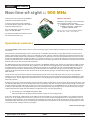
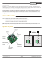
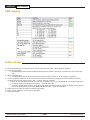
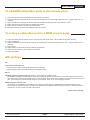
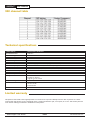
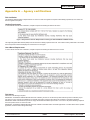
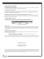
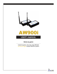
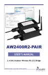
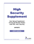
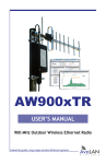
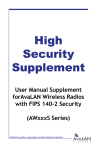
AW900mT
User’s Manual
Point-to-multipoint
Industrial-grade, ultra-long-range 900 MHz
non-line-of-sight wireless Ethernet systems
AW900mT
User’s Manual
Non-line-of-sight :: 900 MHz
AW900mT OEM Module
Thank you for your purchase of the AW900mT
multipoint wireless Ethernet module.
900 MHz non-line-of-sight, point-to-multipoint
radio transceiver module. Includes:
n
— (1) AW900mT RF module — RPSMA female
n
— (1) AWP8 8-inch pigtail — RPSMA male
— (1) to RPTNC bulkhead female
If you have any questions when configuring
your AvaLAN system, please send an e-mail to
[email protected].
For a live technician, please call technical
support at (650) 384-0000.
Requires antenna: Use with AW2, AW5H-900, AW5P-900,
AW6, AW10, AW11, or AW15 — all FCC approved
For advanced installation information, please
visit www.avalanwireless.com.
Operational summary
The AvaLAN AW900mT module allows a user to create an ultra-long-range, wireless Ethernet network for up to 16 subscriber units per
access point.
The access point (AP) automatically scans for the best of the 12 available radio channels, encrypts Ethernet data received from the
network, and transmits it wirelessly to the correct subscriber unit (SU). The AP is constantly monitoring the network performance and
automatically changes channels if the performance is degraded due to interference. The user may manually select any of the 12 radio
channels by toggling DIP switch settings (see Page 5). It is possible to operate up to 12 APs in the same area with each AP on a different
channel. To avoid interference, the APs should be spaced at least 10 feet apart. Typically the AP is attached to the wired network via an
Ethernet cable. The AP does not have a MAC/IP address.
Any 10BaseT Ethernet client device (ECD) can be connected to an AW900mT subscriber unit. Each SU encrypts Ethernet traffic received
from the attached ECD and transmits the data wirelessly to its AP. Each SU can be plugged directly into an ECD without adding drivers
or loading software. Crossover cables are never needed. Only one ECD can be attached to each SU, and fixed IP addresses are recommended for the attached ECDs. The DIP switches on the SU should be in the default OFF setting. To avoid overloading the module’s
receiver, the SU should be placed at least 10 feet from the AP, and 100 feet spacing is recommended if using the higher gain AW11 or
AW15 antennae.
The SU does not have its own MAC/IP address. AvaLAN modules use electronic network keys that allow the user to group modules
together to form a network. Network keys are shared between modules by connecting an Ethernet cable between the RJ45 ports while
the modules are in “key exchange mode” (modules that are in “key exchange mode” display the 6 LINK QUALITY LEDs blinking sequentially back and forth).
To share the keys and to create the network, the user first selects which module will be the access point (AP) by setting DIP switch 1 ON
(see Page 5 for DIP details). The other modules will function as subscriber units (SUs) and do not require any DIP settings. The user then
connects an Ethernet cable from the AP to each SU to transfer the network keys. For the AW900mT the key exchange will occur though
an Ethernet cable attached to the supplied POE injector. Key exchange will not work through a switch or hub. Once the key sharing is
complete the AP and SU change their LED displays in confirmation of the successful programming:
— The SU blinks one of the GREEN LINK QUALITY LEDs.
— The AP illuminated the LED labeled RF RX and the AP remains in “key exchange mode.”
n
n
If the user’s needs change, additional SUs can be added to the network and/or a SU can be reprogrammed to join a different network
and/or a SU can be changed into an AP and/or an AP into a SU. The modules cannot be damaged by incorrect programming. If DIP 1 is
accidentally toggled then DIP 1 can be turned back and the module still retains all the network associations it had in its previous mode
(assuming that the module had not yet successfully key exchanged with a new network). An AP can be reset by programming it as a SU
to a new AP and then turning it back into an AP again.
Please see the next page
Technical support :: (650) 384.0000
PAGE 2
www.avalanwireless.com
User’s Manual
AW900mT
Continued from Page 2
SUs that have not yet received a network key boot up in “key exchange mode” and wait to receive a key. SUs that have received a
network key will boot up for 5 seconds in “key exchange mode” and will look to see if a new AP is present. If a new AP is present, then
the SU exchanges keys with the AP, otherwise the SU begins normal operation after the 5 seconds.
APs that have not yet issued network keys boot up in “key exchange mode” until they have issued network keys to at least 1 SU. Once
the AP has issued keys it will only boot up for 5 seconds in “key exchange mode.” If a SU is present during the 5 seconds, then the
AP will issue new keys to the SU and will then remain in “key exchange mode,” waiting for more SUs to be attached. Once all new
SUs have been attached, the AP must be power cycled. The AP will boot up and will enter normal operation after 5 seconds of “key
exchange mode.”
Advanced operation
Please call AvaLAN technical support at (650) 384-0000 if the system topology requires:
— More than 16 subscriber units per access point for roaming/mobility applications
— Multiple access points that use the same network key for roaming/mobility
n
— Low packet loss rates when using broadcast or multicast Ethernet packets
n
n
NOTE: Broadcast and multicast packets (example: DHCP, UDP) are sent once and may experience losses at extended range. Unicast
packets (example: HTTP, TCP) are sent using advanced error correction and retransmission techniques to ensure delivery.
System diagram
LED Display
16 LEDs
1.536 Mb/sec
DIP Switch
8 Pin DIP
Up to 50 miles
RF
RPSMA Female
+21 dBm
output
Power Jack
P5/2.1 mm
Center Positive
4.5-48 VDC
Antenna
Antenna
RF
AW900mT
AW900mT
Power
Power over Ethernet
Lines 4/5 Positive
Lines 7/8 Ground
9-48 VDC
DATA
10BaseT Ethernet
Lines 1/2/3/6
AutoMDIX correction
www.avalanwireless.com
Power Terminal
12-24 VAC or
6-48 VDC Polarity
is auto corrected
PAGE 3
RF
Ethernet 10BaseT
Power
Ethernet 10BaseT
Technical support :: (650) 384.0000
AW900mT
User’s Manual
LED display
Initial setup
1)
2)
3)
4)
Select the module that will operate as the access point (AP) and set DIP switch 1 ON to enable AP operation.
Plug in the access point.
n
— The LINK QUALITY LEDs will blink sequentially showing that the module is hunting for a subscriber unit (SU) to share keys
— with.
Plug in a subscriber unit.
n
— The LINK QUALITY LEDs will blink sequentially showing the module is hunting for an AP to supply a network key.
Connect an Ethernet cable from the AP to the SU and the units will automatically exchange keys over the Ethernet cable (key
exchange will not work through a switch or hub — crossover cables are required).
n
— On the AP, the LINK QUALITY LEDs will still show that the module is still in “key exchange mode” and the RF TX LED will be
— lit showing that the keys exchanged successfully — ignore the other LEDs.
n
— On the SU, the LINK QUALITY LEDs no longer blink sequentially and will show that the module has stopped hunting and now
— has a slowly blinking pulse on one of the GREEN LINK QUALITY LEDs — ignore the other LEDs.
5) Repeat steps 3 and 4 until all SUs are successfully programmed.
6) Power cycle all modules for the new keys to take effect.
7) Deploy the modules.
Technical support :: (650) 384.0000
PAGE 4
www.avalanwireless.com
User’s Manual
AW900mT
To add NEW subscriber units to the access point
1) Disconnect the AP from the network and disconnect power from the AP.
2) Connect an Ethernet cable from the AP to the SU (key exchange will not work through a switch or hub — crossover cables are not
required).
3) Plug in the NEW SU, then plug in the AP. The units will automatically exchange keys over the Ethernet cable.
4) Repeat steps 2 and 3 until all SUs are successfully programmed.
5) Power cycle all modules for the new keys to take effect.
6) Reconnect the AP to the network and deploy the new SU modules.
To re-key a subscriber unit to a NEW access point
1) Select the module that will operate as the access point (AP) and set DIP switch 1 ON to enable access point operation.
2) Plug in the NEW AP.
3) Connect an Ethernet cable from the AP to the SU (key exchange will not work through a switch or hub — crossover cables are not
required).
4) Plug in the SU.
5) Repeat steps 3 and 4 until all SUs are successfully programmed.
6) Power cycle all modules for the new keys to take effect.
7) Deploy the modules.
DIP settings
DIP 1
Access point or subscriber unit
n By selecting DIP 1 ON the module will operate as an access point
n By selecting DIP 1 OFF the module will operate as a subscriber unit
DIP 3-8
Automatic frequency selection mode (DIP switches — DIP 3-8 OFF for automatic mode)
The AW900mT is designed to automatically select and continuously optimize the performance of its radio channel. The radio channel is monitored to ensure it is providing low error rates necessary for successful data transmission. In the event that the error rate
rises, the access point will autonomously change to a new channel. There are 12 non-overlapping channels.
Manual frequency selection mode
The operation of the AW900mT can be restricted to a specific channel within the 900 MHz band by setting DIP switches 3-8 on
the access point as shown in the table on Page 6. The subscriber unit responds to the access point’s choice of channel and its DIP
switches have no effect and do not need to be selected.
Please see the next page
www.avalanwireless.com
PAGE 5
Technical support :: (650) 384.0000
AW900mT
User’s Manual
900 channel table
Technical specifications
CHARACTERISTIC
SPECIFICATION / DESCRIPTION
RF transmission rate
Ethernet throughput
Output power
Receive sensitivity
Radio link budget
Range
Radio channels/bandwidth
Automatic frequency select
Connector types
Status LEDs
Error correction technique
Regulator type
Power consumption
Voltage
1.536 Mb/s
935 Kb/s
+21 dBm (4 Watts EIRP used with 15 dBi antennae)
-97 dBm at 10e-4 BER (-112 dBm with 15 dBi antennae)
148 dB with 15 dBi antenna AW5-5800
50 miles LOS with 15 dBi antenna
12 non-overlapping with 2.0833 MHz spacing and 1.75 MHz occupied bandwidth
Yes, radio channel automatically selected and adaptively optimized
RF RPSMA Female / Ethernet RJ45 10BaseT / Power Jack P5-2.1 mm ID
Power, Ethernet Link, RF RX, RF TX, 4/Channel, and 6/Link Quality
Sub-block error detection and retransmission
Switching regulator
Transmit:1.4 W
Receive: 0.8 W
4.5-48 VDC at screw terminal
9-48 VDC over Ethernet
12-26 VAC at screw terminal
-40o C to 70o C
250 mA at 5 VDC
110 mA at 12 VDC
32 mA at 48 VDC
65 x 65 x 33 mm
Temperature range
Transmit current draw
Size
Limited warranty
This product is warranted to the original purchaser for normal use for a period of 360 days from the date of purchase. If a defect
covered under this warranty occurs, AvaLAN will repair or replace the defective part, at its option, at no cost. This warranty does not
cover defects resulting from misuse or modification of the product.
Technical support :: (650) 384.0000
PAGE 6
www.avalanwireless.com
User’s Manual
AW900mT
Appendix A — Agency certifications
FCC Certification
The AW900mT OEM RF Module complies with Part 15 of the FCC rules and regulations. Compliance with labeling requirements, FCC notices and
antenna regulations is required.
Labeling Requirements
In order to inherit AvaLAN’s FCC Certification, compliance requires the following be stated on the device:
Figure 1. Required FCC label for OEM products containing the AvaLAN AW900mT OEM RF module
The Original Equipment Manufacturer (OEM) must ensure that FCC labeling requirements are met. This includes a clearly visible label on the outside
of the final product enclosure that displays the contents shown in the Figure 1.
User’s Manual Requirements
In order to inherit AvaLAN’s FCC Certification, compliance requires the following be stated in the user’s manual:
FCC Notices
Adherence to the following is required:
IMPORTANT: The AW900mT OEM RF Modules have been certified by the FCC for use with other products without any further certification (as per
FCC section 2.1091). Changes or modifications not expressly approved by AvaLAN could void the user’s authority to operate the equipment.
IMPORTANT: OEMs must test their final product to comply with unintentional radiators (FCC section 15.107 and 15.109) before declaring compliance
of their final product to Part 15 of the FCC Rules.
IMPORTANT: The AW900mT OEM RF Modules have been certified for fixed base station and mobile applications. If modules will be used for portable
applications, the device must undergo SAR testing.
www.avalanwireless.com
PAGE 7
Technical support :: (650) 384.0000
FCC-Approved Antennas (900 MHz)
Fixed base station and mobile applications
AvaLAN Modules are pre-FCC approved for use in fixed base station and mobile applications. When the antenna is mounted at least
20 cm (8”) from nearby persons, the application is considered a mobile application.
Portable applications and SAR testing
When the antenna is mounted closer than 20 cm to nearby persons, then the application is considered “portable” and requires an
additional test be performed on the final product. This test is called the Specific Absorption Rate (SAR) testing and measures the
emissions from the module and how they affect the person.
RF exposure (This statement must be included as a CAUTION statement in OEM product manuals.)
WARNING: This equipment is approved only for mobile and base station transmitting devices. Antenna(s) used for this transmitter
must be installed to provide a separation distance of at least 20 cm from all persons and must not be co-located or operating in conjunction with any other antenna or transmitter.
To fulfill FCC certification requirements:
1. Integrator must ensure required text [Figure 1] is clearly placed on the outside of the final product.
2. AW900mT Module may be used only with Approved Antennas types that have been tested with this module.
Table 1. Type certified antennae
Antenna warning
WARNING: This device has been tested with Reverse Polarity SMA connectors with the antennas listed in Table 1 Appendix A. When
integrated into OEM products, fixed antennas require installation preventing end-users from replacing them with non-approved antennas. Antennas not listed in the tables must be tested to comply with FCC Section 15.203 (unique antenna connectors) and Section
15.247 (emissions).
IC (Industry Canada) Certification
Labeling requirements for Industry Canada are similar to those of the FCC. A clearly visible label on the outside of the final product
enclosure must display the following text:
Integrator is responsible for its product to comply with IC ICES-003 & FCC Part 15, Sub. B - Unintentional Radiators. ICES-003 is the
same as FCC Part 15 Sub. B and Industry Canada accepts FCC test report or CISPR 22 test report for compliance with ICES-003.
[email protected]
Technical support :: (650) 384.0000
For advanced installation information visit
www.avalanwireless.com
©2004 — 2007 AvaLAN Wireless Systems Incorporated. All rights reserved. AvaLAN Wireless and the AvaLAN Wireless logo are registered trademarks of AvaLAN Wireless Systems
Incorporated. All other trademarks are property of their respective owners. AvaLAN Wireless makes no representations or warranties with respect to the accuracy, utility, or
completeness of the contents of this publication and reserves the right to make changes to specifications and product descriptions at any time without notice. No license, express
or implied, by estoppel or otherwise, to any patents or other intellectual property rights is granted by this document. Particular uses or applications may invalidate some of the
specifications and/or product descriptions contained herein. The customer is urged to perform its own engineering review before deciding on a particular application. AvaLAN
Wireless products are not designed for use in medical, life saving, or life sustaining applications. 07.07.2007