1
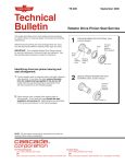
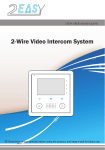
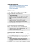
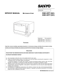
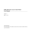
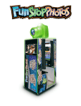
ENGLISH SINGLE VIDEO INTERCOM SYSTEM USER’S MANUAL VT2000 series (05 Ver.) VERSION V1.1 FEATURES ■ The system can expand to 2 outdoor stations (up to 8 outdoor stations or cameras) in connection with 5 monitors or audio-phones ■ Intercom communication between monitors or audio-phones ■ Simple wiring with bus of 4-core cable ■ Lock connected from outdoor station * The sketch map only shows structure of the system * Differences may exist between actual products and sketch map, owing to different products configuration. Please Refer to the relevant section of this manual Read this manual carefully before installation, and keep it for future reference. CONTENTS 1. INDOOR MONITOR ----------------------------------------------- 1 1.1 Indoor Monitor VT 680 --------------------------------------------- 1 1.2 Indoor Monitor VT 684 --------------------------------------------- 2 1.3 Indoor Monitor VT 686 -------------------------------------------- 3 1.4 Indoor Monitor VT 687 -------------------------------------------- 4 1.5 Audio-phone VT 672 ----------------------------------------------- 5 1.6 Audio-phone VT 673 ----------------------------------------------- 5 2. OUTDOOR STATION -------------------------------------------- 5 2.1 Outdoor Station VT 580 -------------------------------------------- 5 2.2 Outdoor Station VT 581 -------------------------------------------- 6 2.3 Outdoor Station VT 584 -------------------------------------------- 6 3. ADAPTOR -------------------------------------------------------- 6 4. OPERATION ------------------------------------------------------ 7 5. MOUNTING INSTRUCTION ------------------------------------ 9 5.1 Indoor Monitor mounting ------------------------------------------ 9 5.2 Outdoor Station mounting ----------------------------------------10 6. SYSTEM CONNECTION ---------------------------------------- 11 7. MAIN TECHNICAL PARAMETER ------------------------------ 16 8. MAINTENANCE AND CARE INSTRUCTIONS ----------------- 16 1. INDOOR MONITOR 1.1 Indoor Monitor VT 680 VOLUME RING VOL UME ADJ UST JS-VP JS-AP JP-VD JP-LK DC IN Dimension:220(H)×190(W)×55(D) 1. Screen 11. Ringing volume adjust 2. Indicator 12. JS-VP connect port to Bracket Board 3. Monitor button 13. JS-AP connect port for audio-phone 4. Unlock button 14. JP-VD Video impedance setting 5. Intercom-Call button 15. JP-LK Unlock mode setting 6. Handset 16. DC input for(VT 680) 7. Loudspeaker 17. AC connection for (VT 680P) 8. Brightness adjustment 18. Wall Mounting Bracket 9. Contrast or Color adjust 19. JW-VP Cable Wiring port 10.Hang up latch 20. JS-VP connection port for indoor monitor -1- 1.2 Indoor monitor VT 684 CONTRAST BRIGHT RING VOLUME ADJUST JS-VP JS-AP JP-VD JP-LK Dimension: 220(H)×198(W)×55(D) 1. Screen 11. Ringing volume adjust 2. Indicator 12. JS-VP connect port to Bracket Board 3. Monitor button 13. JS-AP connect port for audio-phone 4. Unlock button 14. JP-VD Video impedance setting 5. Intercom-Call button 15. JP-LK Unlock mode setting 6. Handset 16. DC input for (VT 684) 7. Loud speaker 17. AC connection for (VT 684P) 8. Brightness adjust 18. Wall Mounting Bracket 9. Contrast or colour adjust 19. JW-VP Cable Wiring port 10.hang up latch 20.JS-VP connection port for indoor monitor -2- 1.3 Indoor Monitor VT 686 SIDE VIEW 1 2 3 8 9 4 UNLOCK TALK MONITOR INTERCOM 5 FREEHAND VIDEO INDOOR PHONE 6 1. Press TALK and, INTER 2. Press Monitor to surven Camers sequentialy. CONTRAST 7 BRIGHT 13 14 15 16 17 RING VOLUME ADJUST JS-VP JS-AP 10 JP-VD JP-LK 18 19 20 11 SCREW ADJUST 12 Dimension:220(H)×190(W)×55(D) 1. Screen 11. DC input for(VT 686) 2. Loudspeaker 12. AC connection for(VT 686P) 3. Function keyboard 13. Ringing volume adjust 4. Instruction tip 14. JS-VP connection port to Bracket Board 5. Contrast and color adjust 15. JS-AP connect port for audio-phone 6. Brightness adjust 16. JP-VD Video impedance setting 7. Keyboard Cover 17. JP-LK Unlock mode setting 8. Indicator 18. JS-VP connection port for indoor monitor 9. Microphone 19. JW-VP Cable Wiring port 10. Talk volume adjustment 20. Wall Mounting bracket -3- 1.4 Indoor Monitor VT 687 CONTRAST BRIGHT PLAY R EC TIME 5 AUTO RING VOLUME ADJUST JS-VP JS-AP JP-VD JP-LK Dimension:220(H)×198(W)×55(D) 1. Screen 13. Contrast or Color adjust 2. Indicator 14. Hang up latch 3. Monitor button 15. Ringing volume adjust 4. Unlock button 16. JS-VP connect port to Bracket Board 5. Intercom-Call button 17. JS-AP connect port for audio-phone 6. TIME button 18. JP-VD Video impedance setting 7. AUTO button 19. JP-LK Unlock mode setting 8. REC button 20. DC input 9. PLAY button 21. Wall Mounting Bracket 10. Handset 22. JW-VP Cable Wiring port 11. Loudspeaker 23. JS-VP connection port for indoor monitor 12. Brightness adjustment -4- 1.5 Audio-phone VT 672 1. Loud Speaker 2. Intercom-Call button 3. Unlock button 4. Handset 5. Handset curve 1. Intercom-Call button 2. Unlock button 3. Handset 4. Handset curve Dimension: 215(H)×80(W)×45(D) 1.6 Audio-phone VT 673 Dimension: 210(H)×90(W)×45(D) 2. OUTDOOR STATION 2.1 Outdoor Station VT 580 1. Camera 2. Speaker 3. Call button 4. Microphone 5. Connection terminal 6. Unlock port LB 7. Mounting bracket 8. Fixing hook Dimension: 128(H)×98(W)×43(D) -5- 2.2 Outdoor Station VT 581 1. Microphone 2. Camera 3. Speaker 4. Call button 5. Mount box 6. Panel fixed position Note: Connection terminal Dimension: 162(H)×130(W)×50(D) and unlock port LB are designed on PCB Board. 2.3 Outdoor Station VT 584 1. Microphone 2. Camera 3. Call button JS-VP 4. Speaker LB 5. Camera angle adjust 6. Connection Port 7. Unlock Port LB 8. Mounting fixed position Dimension: 150(H)×95(W)×43(D) 3. ADAPTOR The adaptor is only for VT 680/684/686/687. VT680P/684P/686P are operated by SMPS. Note: Different countries or regions may require different adaptors because of different power voltage or styles. -6- 4. OPERATION ■ Normal Operation Instructions 1) When visitor presses the “CALL” button on the outdoor station, the electronic bell in indoor monitor chimes, at the same time, the screen displays the visitors’ images. 2) When pick up the handset (press “TALK” button on free hand indoor monitor ), you can talk with the visitors for 90 seconds. If nobody answers the phone, the screen will turn off in 30 seconds automatically. If the system connects two or more indoor monitors, when one handset is picked up, the other indoor monitors will automatically close the screen. 3) Press “MONITOR” button on indoor monitor, the screen will display the view in front of the door, press again or wait in 30 seconds, system will quit out automatically. 4) Press “UNLOCK” button to open the electronic lock during monitoring or talking. 5) Adjust the contrast and brightness to change the image and brightness level. 6) Adjust the volume potentiometer on back of monitor to change volume level. ■ Operation for Intercom 1) When system is connected with multi monitors/audio-phone, intercom is available. 2) Intercom calling can be started by any indoor monitor. Pick up the handset and press “CALL” button (for free hand monitors, press “CALL” button directly), other indoor monitors/ audio-phone under hang on condition are all ringing, pick up handset (free hand monitor press “TALK” button) communicate between indoor monitors. 3) Intercom function is prior to monitor function, but calling function is always first. ■ Operation for Multi Outdoor Stations (Cameras): 1) When outdoor station calls, the screen will display the view of the called outdoor station automatically and communicate is available after pick up the handset. 2) The indoor monitor can supervise each outdoor stations (cameras) in turns. Firstly, it displays image from No.1 outdoor station; press second time, displays image next outdoor station, after supervising the last image, press “MONITOR” button will close. -7- 3) When monitoring or talking, press “UNLOCK” button just open the lock connected with the being supervised outdoor station. ■ Selecting Ring Tune 1) When monitor is standby, press “UNLOCK” button for 2 seconds, the monitor plays current ring tune, and entering into the tune selecting mode. 2) Sequentially press “UNLOCK” button, select ringing tone as you like. 3) If no operation within 30 seconds, selected ringing tune will be saved automatically. ■ Image Memo ( VT687 only ) 1) Image record by hand: Press “REC” button to save the image of visitor when the screen is turned on. 2) Image record automatically: The indicator LED turns orange from red when press “AUTO”, then the function of the image recording works automatically. The visitor’s image will be recorded automatically after 5 seconds when “CALL” button was pressed. If you want to close the function of image recording automatically, press “AUTO” button again, and the indicator LED turns red from orange. 3) Image review Press “PLAY” to view the image recorded in the monitor. You can read the images sequentially, when you press “PLAY” button. Playing state will exit after nine seconds when “PLAY” isn’t pressed any more. 4) Clock setting: Press “MONITOR” to trigger screen first. Press “TIME”, the [Minute] is twinkling, you can adjust the Minute via pressing “PLAY” button. Then press “TIME” again, then the [Hour] is twinkling, and you can adjust the Hour via pressing “PLAY” button. The operation of [Day],[Month] and [Year] is the same way as Minute’s .(Note: The number only can be increased) -8- 5. MOUNTING INSTRUCTION 5.1 Indoor Monitor mounting Accessory fittings: 1) Mounting Bracket and special 4 core wire are already connected with indoor monitor. 2) Three 4X25 self-taping screws are used for fastening the Mounting Bracket on the wall. Installation steps ■ Installation height of indoor monitor, usually from 145- 160CM (refer to sketch map) ■ Take out the cables and then fix bracket with the self taping screw. ■ Refer to the system connection section of this manual, connect cables or wires on the mounting bracket on the ports correctly. ■ Connect the indoor monitor with the mounting bracket port, then hang the indoor monitor/handset firmly on the bracket. Remark: Installation are similar for VT680/684/686/687 Example for VT680 as below. -9- 5.2 Outdoor Station mounting The location for outdoor station should keep away from snow, rain, and intensity light. The height same as indoor monitor, usually at 145~160CM. VT 584 installation steps: Drill a hole (75X75X35mm) on the wall at recommended height, fix mounting bracket, press outdoor station which connected with cables and adjust the camera angle correctly firmly into place, and then fix panel and bracket with screw . VT 580 installation steps: Fix mounting bracket with screw at recommended height, press outdoor station which connected with cables firmly into place, and then fix with screw from bottom. VT 581 installation steps: Drill a hole (140X115X35mm) on the wall at recommended height, fix Mount box on wall, press outdoor station which connected with cables firmly into place, and then fix panel and mount box with 4 screw firmly. - 10 - 6. SYSTEM CONNECTION For indoor monitors, first, connect the cable in the mount bracket, then connects the JS-VP port with the monitor by using 4 core cable (which is GX-4P-2C3 in following diagram). 1R Power positive. +12V present when outdoor station calling or being supervised. 2W Power negative (GND) 3Y Image signal (Video signal) 4B Talk and control signal It’s recommended to use RVVP 4X0.3mm2 shielded cable. And when distance is over 50m, we suggest to use additional co-axle cable RG-59 (or 3C-2V) to connect 3Y and 2W. AC ~ Door Station JS-VP JS-AP JP-VD * Note 1 JP-LK DC IN GX-3P-150 1 2 3 * Note 2 Monitor backview * Note 3 * Note 4 GX-4P-2C3 Power Supply JS-VP REF:210W 4B 3Y 2W 1R JW-VP Bracket Electronic latch Extended monitors ■ Note 1: For monitors of SMPS, please input the AC plug to the AC socket directly. ■ Note 2: LB includes 3 wiring Terminals: ‘1’-Normally Opened contact, ‘2’- Common contact, ‘3’- Normally Closed contact. If the latch is activated when powering, connect it between ‘1’ and ‘2’ terminal; if the latch is deactivated when powering, connect it between ‘2’ and ‘3’ terminal. ■ Note 3: JP-VD is used for setting the video impedance. When there is only one indoor monitor, keep the jumper (which is already on JP-VD ). But when multi monitors are installed, be sure of taking away all JP-VD of monitors except only the last monitor. ■ Note 4: JP-LK is used for Unlock operation type setting : - 11 - With Jumper (Dry contact mode). Extra power supply for latch must be installed, and nearly all kinds of electronic latch can be used, please see Note 2 for reference. Incidentally, in this mode, you can continue talking and monitoring during unlock operation. 1 2 3 POWER SUPPLY Dry contact mode Without Jumper (DC output for latch mode) The latch can directly connect with the door station, and the power for activating latch is provided through monitor. During the unlock operation, the monitor will close the talking and monitoring automatically. Noted. The latch is restricted to select, only the kind of latch that activated when powering can be used, and rated voltage is 12V, less than 500mA consumption. 1 2 3 DC output mode - 12 - Wire Connection for VT581/584 VT581/584 is connected with the cable directly. See diagram for VT584. One 4 core cable is provided, with VT 581/584 for connecting the JS-VP LB 1 2 3 4 1 2 3 cable(which is GX-4P-150 in the diagram) Wires in colour on terminal: GX-3P-150 POWER SUPPLY 1-RED(1R) GX-4P-150 To Monitor Bracket JW-VP 2-BLACK(2W) 3-YELLOW(3Y) NORMALLY OPEN TYPE 4-WHITE(4B) Wire Connection For VT 672 VT 672 is directly connected with the indoor monitor, which no additional power needed. JS-AP port on VT 672’s PCB connects with JS-AP port on indoor monitor. VT672 provided 2 pcs of 3 core cables, colour listed as: 1-red (+12), 2-black (2W), 3-white (4B). When use RVVP4 cable for VT 672, please connect the unwanted wires and shield layer on the two terminals of 2W. AC ~ JS-VP VT 672 JS-AP JP-VD INDOOR MONITOR BACK JP-LK GX-3P JP-LK DC IN JS-AP GX-3P GX-4P INSIDE (90 Degree ROTATE) JS-VP REF:210W 4B 3Y 2W 1R JW-VP MOUNT BRACKET WIRING INDOOR MONITORS AND OUTDOOR STATION - 13 - BACK 1 2 3 - 14 POWER SUPPLY NORMALLY-OPEN TYPE OUTDOOR STATION AC ~ DC IN MOUNT BRACKET INDOOR MONITOR JW-VP JW-VP JS-VP JP-LK JP-VD JS-VP * JP-VD TAKE AWAY BACK JS-AP Power Supply OTHER EXTENDED INDOOR PHONES AC ~ DC IN MOUNT BRACKET INDOOR MONITOR JS-VP JP-LK JP-VD JS-VP JW-VP * JP-VD RESERVED BACK JS-AP Wiring Diagram For Extended Monitors (1 door stations : N monitors ) REF:210W 4B 3Y 2W 1R REF:210W 4B 3Y 2W 1R Wiring Diagram For Extended Monitors and Outdoor Stations BACK BACK DC IN MOUNT BRACKET INDOOR MONITOR - 15 RVV 2*1.0 RVV 2*1.0 Power Supply Power Supply OTHER EXTENDED INDOOR PHONES MOUNT BRACKET INDOOR MONITOR INDOOR MONITOR DC IN JS-VP JP-LK JP-VD JS-VP INDOOR MONITOR JW-VP * JP-VD RESERVED BACK JS-AP 4B 3Y 2W 1R NORMALLY-OPEN TYPE JW-VP JS-VP JP-LK JP-VD JS-VP * JP-VD TAKE AWAY BACK JS-AP AC ~ REF:210W POWER SUPPLY * When using 2 OUTDOOR STATIONS, Replace the "210W with a "2WAY" Board. AC ~ 4B 3Y 2W 1R 4B 3Y 2W 1R 4B 3Y 2W 1R 1 2 3 POWER SUPPLY NORMALLY-OPEN TYPE OUTDOOR STATION No.2 1 2 3 OUTDOOR STATION No.1 ( 2 door stations : N monitors ) REF:2WAY 7. MAIN TECHNICAL PARAMETER 1) Power supply for indoor monitor: DC 15~18V (VT680/684/686/687 supplied by Adaptor) AC 100~240V (VT680P/684P/686P supplied by SMPS) 2) Power supply for outdoor station: DC 10~12V (Supplied by indoor monitor) 3) Audio-phone (VT 672): 4) Power consumption: DC10~12V (Supplied by indoor monitor) Standby 0.5W; Working status 15W (for kits) 5) Indoor monitor screen: 6) Camera Lens: 3.6mm, 72 degree horizontal visual angle 4 inch B/W CRT or 4 inch color TFT 7) Resolution: >300 TV lines 8) Video signal: 9) Connection mode: 1Vp-p, 75Ω, CCIR standard 4 wire, polar 10) Surveillance auto-off time: 11) Talk auto-off time: 30 seconds 90 seconds 8. MAINTENANCE AND CARE INSTRUCTIONS 1) All components should be protected from violence vibration. And not allow to be 2) To clean the Lens& Screen by using hands or wet cloth is forbidden. 3) Please do the cleanness with soft cotton cloth, please do not use the organic or impacted, knocked and dropped. chemical clean impregnant. If necessary, please use a little pure water or dilute soap water to clean the dust. 4) Image distortion may occur if the video door phone is mounted too close to magnetic field e. g. Microwaves, TV, computer etc. 5) Please keep away the video door monitor from wet, high temperature, dust, caustic 6) You must use the right adaptor which is supplied by the manufacture or approved by and oxidation gas in order to avoid any unpredictable damage. the manufacture. 7) Pay attention to the high voltage inside the products, please refer service only to a trained and qualified professional. - 16 - The design and specifications can be changed without notice to the user. Right to interpret and copyright of this manual are preserved. VTK-0612