1
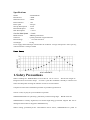
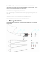
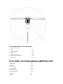
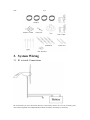
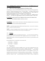
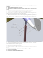
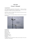
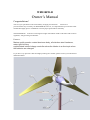
WFD300W-B
Owner’s Manual
Congratulations!
You have just purchased a adv anced battery charging w ind turb ine.
We be lieve
you will find it easy to install your WFD300W-B; however, it is important that you read this entire
manual thoroughly prior to installation to assure proper performance and safety.
The WFD300W-B consists of a 9 kilogram weight wind turbine rated at 300 watts and a built-in
regulators, self-governing mechanisms.
Features:
Marine quality powder coated aluminum body, all stainless steel hardware,
water tight housing
sophisticated internal charge controller slows the blades to a silent spin when
the batteries are charged
If y ou hav e a ny ques tions after th oroughly readi ng t he manual, please co ntact y our aut horized
distributor/dealer.
Specifications
Model
: WFD300W-B
Rated Power
: 300W
: 500W
Maximum Power
Rotor Diameter
: 1.5m
Rotor speed
: 550 rpm
Start-up Wind Speed : 2.5m/s
Rated Wind Speed
: 12m/s
Max Wind Speed
: 4 0 m/s
Cut-Out Wind Speed : 13 m/s
Blade material
: ABS Engineer Plastic
Generator
: 3 phase permanent magnet alternator
Rated Voltage
:
12V/24V/36V/48V
Net Weight
: 12.5kg
It can su pply about 50kwh per month under the condition: average wind speed is 12m/s per day,
valid wind hours is 210h per month
Power Curve
1. Safety Precautions
When i nstalling t he WFD300W-B, exe rcise due car e at al l tim es. The tur bine weighs 12
kilograms and is aw kward i n sh ape. It is best t o plan th e i nstallation carefully i n a dvance a nd
enlist some help when erecting the machine in order to avoid accidents.
Complete as much of the installation procedure as possible at ground level.
Choose a calm, dry day for your installation if possible.
WFD300W-B blades are quite sharp, particularly on their trailing edges.
Handle with care.
WFD300W-B is r obustly engineered, b ut c ontains high-energy p ermanent magnets that can be
damaged if the machine is dropped or handled heavily.
When r unning, p articularly if disc onnected from the ba tteries, WFD300W-B is ca pable of
producing high voltages. Caution must be exercised at all times to avoid electric shocks.
Always observe correct polarity when connecting WFD300W-B to an electrical circuit.
polarity connection will result in damage to the wind generator.
Reverse
The WFD300W-B must be appropriately fused at all times.
Never approach th e path of t he blades w hen t he m achine is oper ating as se vere p ersonal injury
could result.
Always stop the machine and secure the blades before attempting maintenance.
Ensure that all batteries are disconnected when undertaking maintenance.
2.
Package Contents
Compare the parts shown in Figure 1 to ensure that the contents of the box contain all
necessary parts.
Name and Quantity of Each Components
1 – Generator assembly
2 – Tail
3 – Tail component
4 - Blades
5 - Flange for blades
6 – Bolts, Nuts and Washer
7 – Nose cone
1 set
1 pc
2 pc
3 pc
1 pc
1 set
1 pc
The user can buy as option the tower and tower attachment from us as below:
Tower
Tower Base
Tightwire
Tower Clamp
Nuts and Bolts
Tightwire Clamps
Pivot Bolt and Nut
Turnbuckles
Anchor
3 pc x 1.5m length
1 pc
4 pc
2 pc
4 set
16 pc
1 set
4 set
4 pc
Nail
2 pc
3. System Wiring
3.1 El ectrical Connections
We recommend you wire the turbine directly to the battery bank to its ow n set o f battery posts.
This internal regulator will independently monitor the battery and charge as necessary.
Note: WFD300W-B 12V version requires one piece of
24V version requires 2 pieces, etc…
12V/200Ah battery, and
3.2 Wire size from wind generator to battery bank
Connecting wire between W FD500W-B and the battery bank should be appropriately
sized to m inimize tran smission lo sses. For low voltag e m achines transm ission
losses are a lways a con sideration, s o it is advisable to keep wire runs as sho rt as
possible and be prepared to use heavier gauge wire for longer runs.
Typically, you should use copper w ire of at least 4.5 square mm conductor across
section. For longer runs approaching 20 meters you should consider 6 square mm.
CAUTION: MAKE SURE THE TURBINE IS DISCONNECTED FROM THE
BATTERIES DURING INSTALLATION.
CAUTION:
CONNECTIONS S HOULD BE I NSPECTED PERIODICALLY FOR S IGNS
OF CORROSION AND CLEANED WHEN NECESSARY
All electrical power cables should be physically protected.
tower or conduit for maximum protection.
NOTE:
Run the wires inside the
The yaw can support a total of 70 kg in wire weight. For higher wire weights, you
must install a strain relief to minimize the stress put on the hanging wires.
NOTE:
3.3 Fusing
The WFD300W-B is capable of producing high amperages. As with all electrical installations,
you must pro tect each of your turb ines w ith a properly sized fus e or circ uit breaker.
The
WFD300W-B should be wired with an appropriately sized “slow-blow” type fuse between itself
and the batteries.
Recommended Size for Circuit Breakers or Slow-Blow Fuse
24-volt model : 50 amps D.C.
36-volt model : 35 amps D.C.
48-volt model : 25 amps D.C.
3.3
Regulation
The charge c ontroller bui lt ins ide t he nacelle s erves as the c entral connection point f or t he
electrical components in the system and it provides 2 valuable control functions. 1) It rectifies
the AC output from the turbine into direct current(DC) and charge the battery. 2) The controller
continually m onitors t he b attery voltage a nd c ompares i t to the regulation s et p oint. Th e
regulation set point is factory set to 30.2V(24V Turbine) or 45V(36V Turbine). When the battery
voltage rises above the set point, it automatically stops charging the battery.
It will wait for
the ba ttery voltage t o drop.
Normal char ging wi ll resum e when t he battery vo ltage dro ps
slightly below th e f ully charge level.
25.2V(37.8V for 36V turbine).
For 2 4 V t urbine the c ontroller wil l res ume c harging at
4. Mounting To Tower
4.1
Hub and Rotor Assembly
Mounting the Blades. Please see the pictures below.
Tighten all the screw with wrench to 10-12 foot lbs(13.6-16.3 Nm)
4.2 Mounting the Hub and Rotor
Carefully slide the blade assembly onto the alternator shaft. Place the washers and
Nut on the shaft. Tighten the nut to 50-65 foot pounds(68-88 Nm). See pictures below.
Note :
when assembling the blades to t he hub, pl ease take care of the
bolt position.
2 bolts shall go down the hub while one bolt comes up.
Please see the picture
4.3 Attaching Nose Cone
Carefully pl ace the no se co ne ov er the hub an d the blades. Snap the nose c one into plac e.
Insert the screw and tighten. See pictures.
5. Attaching to Pole
5.1 Blade-to-T ower Clearance
Make sure t hat y our t ower all ows for proper clearance of t he blades. A m inimum 100 mm
clearance must be given between the blade tips and any obstruction. Refer to Figure below
The WFD300W-B is desig ned to be mounted on a steel pipe of outer diameter 48mm(inner dia.
42mm) We offer wire guyed tower as option. Contact your dealer for details.
5.2 S tep by Step Instructions
1) Run the wires from the battery(do not connect to the battery), through the pole to the top of
the tower. Be sure not to connect the wires to t he b attery until everything el se has b een
completed.
2) Strip the insulation back from each set of wires.
3) Mark both en ds of a ll the w ires w ith ta pe t o i dentify w hich is positive, negative an d e arth
ground.
4) Insulate the connections using either heat shrink tubing or a quality electrical tape.
5) Connect the wires from the WFD300W-B to the wires running to the battery.
6) Once the wires are at tached to the FD2.5-300, gently pull the wires down through the tower
sliding the yaw shaft inside the 48mm O.D./42mm I.D. steel pipe.
7) Slide the yew shaft all t he way down over the end of pole being careful not to pinch the yaw
wires. Be s ure t o le ave enough sl ack in the wires so t hat if necessary , t he turbine can be
removed.
8) Once the yaw shaft is on the tower, use the M10 hex bolts to firmly tighten the yaw to the tower as shown above.
9) Check your WFD300W-B to be sure that it is s ecurely attached to the mounts. Remember
that this attachment will have to hold in high winds.
10) Run all wires from the turbine to the battery.
11) Before attaching the wiring to the battery, make sure that all circuit breakers are in the off
position.
12) Attach wires to the battery. Positive wire to positive, negative to negative.
13) Turn on the circuit breakers
14) You have now completed the installation process.
6.
Testing
6.1 Alternator
The WFD 300W-B uses a t hree-phase br ushless permanent magnet alter nator in ternally rectifies
the power to D.C. The rotor is comprised of Neodymium Iron Bo ron arched magnets, the most
powerful magnet material available. The stator is hand wound for maximum output.
6.2
Charge Controller
The charge controller serves as t he central connection point for the electrical components in the
system and it provides 2 valuable control functions.
It rectifies the AC output from the turbine
into direct current(DC) and charge the battery.
The controller continually monitors th e ba ttery v oltage and c ompares it t o t he regu lation se t
point. The regulation set point is factory set to 15.1V(12V Turbine) or 3 0.2V(24V Turbine), or
45V(36V Turbine), or 60V(48V version). When the battery voltage rises above the set point, it
automatically stops charging the battery. It will wait for the battery voltage to drop.
Normal
charging will resume when the battery voltage drops slightly below the fully charge level. For 12
V turb ine t he co ntroller wi ll res ume cha rging a t 12.6V(25.2V for 24V t urbines, 37 .8V for 36V
turbine and 50.4V for 48V turbine)
Note:
Bad
connections, undersized wires, and inline diodes will cause the internal regulator
to not work properly.
6.3 Bench Testing
Two quick bench tests can verify if your WFD300W-B is providing output.
Test 1
1. Remove blade assembly from turbine and place in a safe location.
2. Spin ro tor shaft w ith y our fi ngers w hile a t t he sa me tim e con necting a nd dis connecting t he
positive and negative yaw wires.
3. With the yaw wires connected, the rotor shaft should become more difficult to rotate and feel
“lumpy”.
With t he y aw w ires disconnected i t s hould s pin free ly. If t hese c onditions d o not
exist, you should contact your turbine dealer.
6.4
Performance Test
Electrical System.
Your battery bank should be a minimum 400 amp hours for 12 V systems,
and 200 amp hours for 24V system and 3 6V system.
If your battery bank is smaller than the
recommended size, battery voltage could quickly rise while the turbine is charging and cause the
internal regulator to prematurely stop charging.
Measure the voltage at the battery terminals to which the WFD300W-B is conne cted.
For the
factory regu lation set point, if the voltage for a 12V s ystem reads 14.1V or higher(24V 28.2;
36V 42.3;
power.
48V 56.4), then the turbine will sense the battery is charged and stop producing
NOTE: THE WFD300W-B ELECTRONICS INCLUDING INTERNAL
DIODES. DO NOT PUT ADDITIONAL BLOCKING DIODES BWTWEEN
THE WFD300W-B AND THE BATTERIES. ANY DIODES BETWEEN THE
FD2.5-300 AND THE BATTERIES WILL PREVENT THE TURBINE FROM
PROPERLY “SENSING” THE BATTERIES.
7. Maintenance Monthly
Check Mechanical Condition
Watch and listen from the tower base.
Use binoculars. There should be no
mechanical noise, rattle or vibration. The blades m ust not wobble. Lower or
climb the tower for inspection, if indicated.
There should be no buzzing either
heard or felt with your hand on the tower m ast. Go to Ele ctrical Problems, if
indicated.
7.2 Inspect the Tower
7.1
Follow all inspection and maintenance requirements of the tower manufacturer. Tighten all
nuts a nd b olts, esp ecially wire cl ips. Check f or cra cks and bent or bro ken parts a t t he
anchors and base structure. Check for broken strands and tighten guys
7.3 Check the Battery
Add only distilled water if needed.( Consult your battery manufacturer guide.)
Tighten battery connections
Remove corrosion and protect terminals
Wipe tops with baking soda solution.
8. Maintenance Annual
Lower tower and give wind generato r a co mplete mechanical check.
Fix or replace any worn or loose parts.
8.1 Check tightness of all tower mounting nuts and bolts and blades mounting bolts.
8.2 Check all bearings. Just perceptible play is acceptable.
8.3 Clean the blades with mild detergent to remove all dirt and debris. Avoid
scratching the surface. Replace blades if they are cracked or damaged.
Specification
Model
WFD300W-B
RATED POWER
300W
MAX POWER
500W
OUTPUT DC VOLTAGE
12V,24V, 36V or 48V
START WIND SPEED
3 m/s
RATED WIND SPEED
10 m/s
SURVIVAL WIND SPEED
40 m/s
Cut-Out Wind Speed
14 m /s
Temperature Range
-40 to +60 Deg. C
ROTOR Diameter
1.50 m
Rotor speed
550rpm
Blade material
Height of tower recommended
Generator
Turbine Weight(kg)
Packing
ABS engineer plastic
6m
3 phase iron Boron Neodymium magnet alternator.
11
One carton, size: 90 x 40 x 21, weight 18 kg