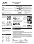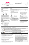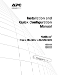
1
Isolated
Extension
Cable
AP9825
AP9825i
Thank You!
Thank you for selecting the Isolated Extension Cable (AP9825 or AP9825i). It has been
designed for many years of reliable, maintenance-free service in combination with your
American Power Conversion (APC) uninterruptible power supply (UPS). APC is dedicated to the development of high-performance electrical power conversion and control
products. We hope that you will find this product a valuable, convenient addition to your
computing system.
Please read this manual! It provides important safety, installation, and operating
instructions that will help you get the most from your Isolated Extension Cable.
Save this manual! It includes instructions for obtaining warranty service.
Contents
Overview . . . . . . . . . . . . . . . . . . . . . . . . . . . . . . . . . . . . . . . 1
Introduction 1
Features of the Isolated Extension Cable 1
Hardware requirements 2
Inventory 2
Setup . . . . . . . . . . . . . . . . . . . . . . . . . . . . . . . . . . . . . . . . . . 4
Introduction 4
Using a different cable 4
Setting up the server end 4
Setup Warning 5
Setting up the UPS end 5
Optional power for UPS End Unit 6
Ordering an additional adapter 6
LEDs . . . . . . . . . . . . . . . . . . . . . . . . . . . . . . . . . . . . . . . . . . . 7
Introduction 7
Server End LEDs 7
UPS End LEDs 8
Polarity errors 8
Using Accessories . . . . . . . . . . . . . . . . . . . . . . . . . . . . . . . . . . 9
Introduction 9
Accessory guidelines 9
Specifications . . . . . . . . . . . . . . . . . . . . . . . . . . . . . . . . . . . 10
Cable requirements 10
Warning 10
RJ45 pin locations 10
Cable definition 11
Product specifications 11
i
Overview
Introduction
American Power Conversion’s Isolated Extension Cable
(AP9825 and AP9825i) is a device that allows you to
lengthen the communications connection between a server
running PowerChute® software and an APC™ uninterruptible power supply (UPS). When standard cables are used for
distances of more than 5 meters, communications can
become unreliable and ground loops can damage computer
serial ports.
If your facility uses large APC UPSs (Matrix-UPS™ or the
Symmetra™ PowerArray™, for example), it may not be
practical to place the server running PowerChute software
close enough to use the standard data cables. With the Isolated Extension Cable, you can house a UPS in one location
and monitor it up to 100 meters away.
Features of
the Isolated
Extension Cable
The Isolated Extension Cable:
• Boosts signals and reduces noise by using a current
loop scheme
• Provides an isolation barrier that prevents damage
from ground loops
• Works with cables up to 100 meters in length
• Requires no configuration after plug in
• Displays information on operation — including some
wiring problems — on LEDs
• Supports all the functions normally available to and
from the UPS
Continued on next page
1
Overview continued
Hardware
requirements
The Isolated Extension Cable requires:
Inventory:
Table 1
The Isolated Extension Cable consists of the parts listed in
the following table.
• UPS-protected power at the Server End
• A serial cable that was provided with PowerChute or
PowerChute plus
• RJ45 Cat 5 cable (15 m supplied). You may want to
use a longer cable. For further information, see
“Cable requirements” on page 10.
• An additional AC Adapter, when used with an APC
Back-UPS® or Back-UPS Pro® model UPS. For further information, see “Optional power for UPS End
Unit” on page 6.
Item
Illustration
UPS End
Unit with
attached
DB9-DB9
Cable
Table 1: Inventory
Continued on next page
2
Overview continued
Inventory:
Table 1
continued
Item
Illustration
Server End
Unit shown
with standard AC
Adapter
(APC Part
Number
AP9505)
Note:
Model
AP9825i
comes with
a universal
AC Adapter
(APC Part
Number
AP9505i)
RJ45 Cable
(15 m)
3
Setup
Introduction
The Isolated Extension Cable requires no configuration.
Using a different
cable
The Isolated Extension Cable comes with 15 meters of RJ45
cable. You can use an existing building cable or a longer
cable only if it fulfills the requirements listed in “Cable
requirements” on page 10.
Setting up the
server end:
Figure 1
Follow the diagram below to set up the Server End Unit
with the RJ45 Cable and the server.
Figure 1:Setting up the server end
Continued on next page
4
Setup continued
Reminder
You must plug the AC Adapter into a receptacle that is protected by UPS power in order to ensure that communication
is maintained during utility failure.
Setting up the
UPS end:
Figure 2
Follow the diagram below to set up the UPS End Unit with
the RJ45 Cable and the UPS.
Figure 2:Setting up the UPS end
Continued on next page
5
Setup continued
Optional power
for UPS End
Unit
The UPS End Unit has an optional power port for use with a
second AC Adapter. Normally, the UPS provides enough
power through the data cable. You must provide extra power
for the UPS End Unit if either of the following conditions
applies:
• you have a heavy load of accessories connected to the
UPS via the DB9 port
• you are connecting to an APC Back-UPS or BackUPS Pro model UPS
Note: If you use an optional AC Adapter, you must plug the
adapter into a receptacle that is protected by UPS
power in order to ensure that communication is
maintained during utility failure.
Ordering an
additional
adapter
6
To order an additional adapter, contact APC at the number
on the back cover of this manual. The reference number for
the standard (North American) AC Adapter is AP9505. The
reference number for the universal AC Adapter (for use
with AP9825i) is AP9505i.
LEDs
Introduction
The Server End Unit has two LEDs; the UPS End Unit has
three. These LEDs provide status information and help diagnose problems.
Server End
LEDs:
Table 2
The following table gives the conditions reported by each
LED on the Server End Unit.
LED
STATUS
Off
LOW BAT
POL ERR
RXD/AC FAIL
POL ERR
Green
DESCRIPTION
Normal condition.
The UPS battery is low.
Red
There is a polarity wiring
problem on the RJ45 cable.
Off
Normal condition for Simple
Signaling (Back-UPS).
Flickering
Green
The computer or accessory is
receiving data from the UPS
(Smart Signaling only:
Smart-UPS, Matrix-UPS, or
Symmetra Power Array).
Solid Green
Red
The UPS is on battery.
There is a polarity wiring
problem on the RJ45 cable.
Table 2: Server End LEDs
Continued on next page
7
LEDs continued
UPS End LEDs:
Table 3
The following table gives the conditions reported by each
LED on the UPS End Unit.
LED
DATA
POL ERR
UPS ON†
UPS OFF
STATUS
CONDITION
Off
Normal condition for Simple Signaling (Back-UPS).
Flickering
Green
The computer or accessory is
sending data to the UPS (Smart
Signaling only: Smart-UPS,
Matrix-UPS, or Symmetra Power
Array).
Red
There is a polarity wiring problem
on the RJ45 cable.
Yellow
The UPS is being turned on by the
server or accessory.
Yellow
The UPS is being turned off by the
server or accessory.
Table 3: UPS End LEDs
† For further information, see “Using Accessories” on
page 9.
Polarity errors
8
A red LED on either unit of the Isolated Extension Cable
indicates a polarity error. Polarity errors are caused by wire
pairs that are reversed. For the wire pairings, refer to
Table 4, “Cable definition,” on page 11.
Using Accessories
Introduction
Accessory
guidelines
The Isolated Extension Cable works in conjunction with
APC accessories, such as Call-UPS® or Share-UPS®, with
certain limitations. Read completely before deciding where
to connect your accessories.
• Do not use more than one Isolated Extension Cable in
a series data path.
• The UPS ON command is not supported when an
APC accessory generating the ON command is connected at the server end. If you want to ensure UPS
ON capability, connect the accessory to the UPS end.
(You can use the accessory’s Advanced Port or one of
its Basic Ports.)
• The Isolated Extension Cable operates at 2400 baud.
Some devices, such as the PowerNet® SNMP
Adapter, can run at higher rates. Locate these devices
such that the Isolated Extension Cable is not in line
with them, or set the device to operate at 2400 baud.
• Use of the Isolated Extension Cable is not supported
when it is connected between a Control-UPS/400
(APC Part Number AP9012) and the AS/400 server.
When using the Isolated Extension Cable with a Control-UPS/400, connect the Isolated Extension Cable
between the Control-UPS/400 and the UPS.
9
Specifications
Cable
requirements
The Isolated Extension Cable is intended for use with cables
that:
•
•
•
•
Comply with 10BaseT wiring schemes
Are no longer than 100 meters
Meet local wiring and safety codes
Have been installed by qualified personnel
Warning
Wiring safety is the responsibility of those installing the
cable. Incorrect installation can result in improper functioning of the device or damage to hardware. The use of
substandard cables can produce toxic fumes in the event of
a fire.
RJ45 pin
locations:
Figure 3
The figure below shows the pin locations on the RJ45
connector.
Figure 3:RJ45 pin locations
Continued on next page
10
Specifications continued
Cable definition:
Table 4
The pairing scheme and the functions of each wire pair of
the RJ45 Cable are provided below.
UPS
End
Function
Server
End
1
2
+24VDC →
UPS–SVR Data →
1
2
3
6
+24VDC →
Low Battery →
3
6
4
5
← +24VDC
← UPS–SVR Data
4
5
7
← !On/Off
8
← On/!Off
Table 4: Cable definition
Product
specifications:
Table 5
7
8
The specifications for the Isolated Extension Cable are
given in the following table.
Item
Specification
Size of unit (h × w × l)
2.5 cm × 6.1 cm × 9.7 cm
1.0 in. × 2.4 in. × 3.8 in.
Length
between units
Normal
15 m (50 ft)
Maximum
100 m (328 ft)
UPS End
24VDC @ 10mA nom.
50mA peak
Server End
24VDC @ 30mA nom.
65mA peak
Power
requirements
Table 5: Product specifications
11
Limited Warranty
American Power Conversion (APC) warrants Isolated Extension Cable to be free from
defects in materials and workmanship for a period of two years from the date of purchase.
Its obligation under this warranty is limited to repairing or replacing, at its own sole
option, any such defective products. This warranty does not apply to equipment which has
been damaged by accident, negligence, or misapplication or has been altered or modified
in any way. This warranty applies only to the original purchaser.
To obtain service under warranty you must obtain a Returned Material Authorization
(RMA) number from APC or a designated APC service center. Products must be returned
to APC or an APC service center with transportation charges prepaid and must be accompanied by a brief description of the problem encountered and proof of date and place of
purchase.
EXCEPT AS PROVIDED HEREIN, AMERICAN POWER CONVERSION MAKES
NO WARRANTIES, EXPRESS OR IMPLIED, INCLUDING WARRANTIES OF MERCHANTABILITY AND FITNESS FOR A PARTICULAR PURPOSE. Some states do
not permit limitation or exclusion of implied warranties; therefore, the aforesaid limitation(s) or exclusion(s) may not apply to the purchaser.
EXCEPT AS PROVIDED ABOVE, IN NO EVENT WILL APC BE LIABLE FOR
DIRECT, INDIRECT, SPECIAL, INCIDENTAL, OR CONSEQUENTIAL DAMAGES
ARISING OUT OF THE USE OF THIS PRODUCT, EVEN IF ADVISED OF THE POSSIBILITY OF SUCH DAMAGE. Specifically, APC is not liable for any costs, such as
lost profits or revenue, loss of equipment, loss of use of equipment, loss of software, loss
of data, costs of substitutes, claims by third parties, or otherwise. This warranty gives you
specific legal rights and you may also have other rights which vary from state to state.
Life support policy
As a general policy, APC does not recommend the use of any of its products in life
support applications where failure or malfunction of the APC product can be reasonably
expected to cause failure of the life support device or to significantly affect its safety or
effectiveness. APC does not recommend the use of any of its products in direct patient
care. APC will not knowingly sell its products for use in such applications unless it
receives in writing assurances satisfactory to APC that (a) the risks of injury or damage
have been minimized, (b) the customer assumes all such risks, and (c) the liability of
American Power Conversion is adequately protected under the circumstances.
Examples of devices considered to be life support devices are neonatal oxygen analyzers,
nerve stimulators (whether used for anesthesia, pain relief, or other purposes), autotransfusion devices, blood pumps, defibrillators, arrhythmia detectors and alarms, pacemakers,
hemodialysis systems, peritoneal dialysis systems, neonatal ventilator incubators, ventilators for both adults and infants, anesthesia ventilators, and infusion pumps as well as any
other devices designated as “critical” by the U.S. FDA, or other competent authority.
Hospital grade wiring devices and leakage current may be ordered as options on many
APC UPS systems. APC does not claim that units with this modification are certified or
listed as Hospital Grade by APC or any other organization. Therefore these units do not
meet the requirements for use in direct patient care.
w w w. a p c c . c o m
Toll free technical support:
Addresses:
U. S. & Canada
Austria
Belgium
Czech Republic
Denmark
Finland
France
Germany
Holland
Hungary
Ireland
Israel
Italy
Japan
Luxembourg
Norway
Poland
Portugal
South Africa
Spain
Sweden
Switzerland
Turkey
U. K.
American Power Conversion Corporation
132 Fairgrounds Road
P. O. Box 278
West Kingston, Rhode Island 02892
USA
1-800-800-4272
0660 6480
0800 15063
0 800 102063
800 18 153
9800 13 374
0 800 906 483
01300818907
0800 0224655
00800 12221
1 800 702000 x 2045
177 353 2206
1678 74731
0120-80-60-90
0800 2091
800 11 632
00800 353 1202
050 553182
0800 994206
900 95 35 33
020 795 419
0800 556177
0800 35390275
0800 132990
American Power Conversion Corporation
(A. P. C.) b. v.
Ballybritt Business Park
Galway
Ireland
American Power Conversion
BR Gotanda 7th Floor
2-30-4 Nishi-gotanda,
Shinagawa-ku
Tokyo 141 Japan
Areas without toll free numbers:
+1 401 789 5735 (USA) or
+353 91 702020 (Ireland)
+7095 916 7166 (Russia)
Serial number:
Entire contents copyright © 1998 American Power Conversion. All rights reserved.
Reproduction in whole or in part without permission is prohibited.
All trademarks are the property of American Power Conversion.
990-0371
Rev. 2
5/98