1
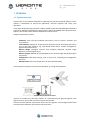
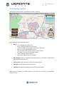
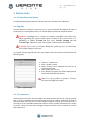
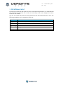
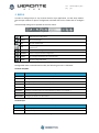
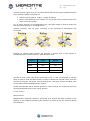
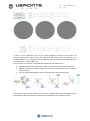
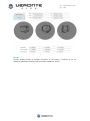
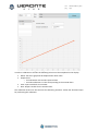
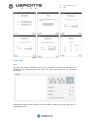
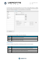
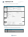
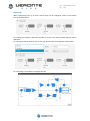
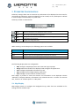
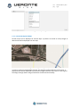
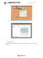
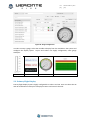
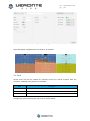
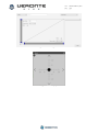
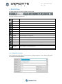
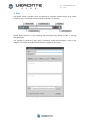
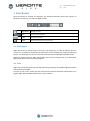
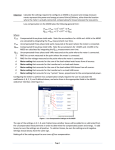
cod: pag: Software User Manual Veronte-SUM-v1.7.docx 1/41 cod: pag: Veronte-SUM-v1.7.docx 2/41 Table of Contents 1. OVERVIEW ......................................................................................................................................... 5 1.1. SYSTEM OVERVIEW................................................................................................................................. 5 1.2. VERONTE PIPE INTERFACE ........................................................................................................................ 6 2. INSTALLATION .................................................................................................................................... 7 2.1. VERONTE PIPE INSTALLATION .................................................................................................................... 7 2.2. UPGRADE ............................................................................................................................................. 7 2.3. PC CONNECTION .................................................................................................................................... 7 3. USER MANAGEMENT ......................................................................................................................... 8 4. SETUP................................................................................................................................................. 9 4.1. VERONTE PIPE ..................................................................................................................................... 10 4.2. VERONTE AUTOPILOT ............................................................................................................................ 11 5. TELEMETRY CONFIGURATION .......................................................................................................... 28 5.1. MAP DISPLAY ...................................................................................................................................... 28 5.2. GAUGE DISPLAY ................................................................................................................................... 30 5.3. PRIMARY FLIGHT DISPLAY ...................................................................................................................... 31 5.4. STICK ................................................................................................................................................. 32 6. FLIGHT PLAN .................................................................................................................................... 34 6.1. WAYPOINT CREATION ........................................................................................................................... 34 6.2. MAPPING TOOL ................................................................................................................................... 35 7. OPERATION ...................................................................................................................................... 38 8. LOG .................................................................................................................................................. 40 9. POST-FLIGHT .................................................................................................................................... 41 9.1. DATA EXPORT ...................................................................................................................................... 41 9.2. TOUR ................................................................................................................................................. 41 Figures and Tables FIGURE 1: VERONTE SYSTEM OVERVIEW ..................................................................................................... 5 FIGURE 2: INTERFACE ................................................................................................................................... 6 FIGURE 3: UPLOAD DISPLAY ......................................................................................................................... 7 FIGURE 4: SETUP TOOLBAR .......................................................................................................................... 9 FIGURE 5: VERONTE PIPE - PREFERENCES .................................................................................................. 10 FIGURE 6: VERONTE PIPE - UNITS ............................................................................................................... 11 FIGURE 7: SETUP - VERONTE ...................................................................................................................... 12 FIGURE 8: SETUP – DEVICES – ACTUATORS ................................................................................................ 13 FIGURE 9: SIGN CONVENTION .................................................................................................................... 14 FIGURE 10: SETUP – DEVICES – SENSOR – ENCODER ................................................................................. 15 FIGURE 11: MAGNETOMETER CALIBRATION PROCEDURE ......................................................................... 15 FIGURE 12: MAGNETOMETER CALIBRATION VALUES ................................................................................ 16 FIGURE 13: SETUP – DEVICES – SENSOR – ENCODER ................................................................................. 17 FIGURE 14: ENCODER CONFIGURATION WIZARD ...................................................................................... 18 FIGURE 15: STICK CONFIGURATION ........................................................................................................... 18 FIGURE 16: SETUP - TELEMETRY ................................................................................................................. 19 FIGURE 17: SETUP - CONTROL .................................................................................................................... 20 FIGURE 18: PID ARCHITECTURE .................................................................................................................. 22 FIGURE 19: PID DIAGRAM .......................................................................................................................... 22 cod: pag: Veronte-SUM-v1.7.docx 3/41 FIGURE 20: PID ELEMENTS ......................................................................................................................... 22 FIGURE 21: FIXED VALUE SETTINGS ............................................................................................................ 24 FIGURE 22: ARCADE MODE SETTINGS ........................................................................................................ 24 FIGURE 23: AUTOMATION DISPLAY............................................................................................................ 25 FIGURE 24: CHECKLIST ................................................................................................................................ 26 FIGURE 25: TELEMETRY TOOLBAR .............................................................................................................. 28 FIGURE 26: MAP SETTINGS ......................................................................................................................... 29 FIGURE 27: BACKGROUND IMAGE EXAMPLE ............................................................................................. 29 FIGURE 28: BACKGROUND IMAGE POSITIONING ....................................................................................... 30 FIGURE 29: BACKGROUND IMAGE MANAGER ........................................................................................... 30 FIGURE 30: GAUGE CONFIGURATION ........................................................................................................ 31 FIGURE 31:PFD CONFIGURATION ............................................................................................................... 32 FIGURE 32: STICK CONFIGURATION ........................................................................................................... 33 FIGURE 33: STICK DISPLAY .......................................................................................................................... 33 FIGURE 34: MISSION TOOLBAR .................................................................................................................. 34 FIGURE 35: WAYPOINT PARAMETERS ........................................................................................................ 34 FIGURE 36: POLYGON CREATION ............................................................................................................... 35 FIGURE 37: MISSION ................................................................................................................................... 35 FIGURE 38: MAPPING MISSION 1 ............................................................................................................... 36 FIGURE 39: MAPPING CREATION................................................................................................................ 36 FIGURE 40: MAPPING PARAMETERS .......................................................................................................... 37 FIGURE 41: MAPPING MISSION .................................................................................................................. 37 FIGURE 42: SIDE PANEL .............................................................................................................................. 38 FIGURE 43: VERONTE PANEL ...................................................................................................................... 38 FIGURE 44: LOG TOOLBAR .......................................................................................................................... 40 FIGURE 45: REPORT INFORMATION ........................................................................................................... 40 FIGURE 46: POST FLIGHT TOOLBAR ............................................................................................................ 41 TABLE 1: USER PERMISSIONS ....................................................................................................................... 8 TABLE 2: SETUP TOOLBAR ............................................................................................................................ 9 TABLE 3: SETUP TABS ................................................................................................................................... 9 TABLE 4: VERONTE PIPE PREFERENCES ........................................................................................................ 9 TABLE 5: SETUP – VERONTE ....................................................................................................................... 11 TABLE 6: CONNECTION PINOUT ................................................................................................................. 12 TABLE 7: DEVICE CONFIGURATION............................................................................................................. 13 TABLE 8: ACTUATOR CONFIGURATION ...................................................................................................... 14 TABLE 9: TELEMETRY CONFIGURATION ..................................................................................................... 19 TABLE 10: SETUP CONTROL ........................................................................................................................ 20 TABLE 11: GUIDANCE SETTINGS ................................................................................................................. 20 TABLE 12: CONTROL TYPE .......................................................................................................................... 21 TABLE 13: PID CONTROL STATUS................................................................................................................ 21 TABLE 14: AUTOMATION ACTIONS ............................................................................................................ 25 TABLE 15: AUTOMATION ACTIVATION EVENTS ......................................................................................... 26 TABLE 16: CHECKLIST CONFIGURATION ..................................................................................................... 27 TABLE 17: TELEMETRY TOOLBAR ................................................................................................................ 28 TABLE 18: WORKSPACE CREATION ............................................................................................................. 28 TABLE 19: STICK CONFIGURATION ............................................................................................................. 32 TABLE 20: MISSION TOOLBAR .................................................................................................................... 34 TABLE 21: POST FLIGHT TOOLBAR .............................................................................................................. 41 cod: pag: Acronyms HUM ID PFD REC RPAS SUM SRS UAV WP Hardware User Manual Identification Primary Flight Display Record Remotely Piloted Aircraft Software User Manual Software Requirements Specifications Unmanned Aircraft Vehicle Waypoint Veronte-SUM-v1.7.docx 4/41 cod: pag: Veronte-SUM-v1.7.docx 5/41 1. OVERVIEW 1.1. System Overview Veronte Pipe is the software designed for operating any Veronte powered platform. Users achieve a combination of easy-to-use application, real-time response and, firstly, safe operations. It has been developed using software standard model of IEEE STD 830-1998, Recommended Practice for Software Requirements Specifications (SRS) and STANAG 4671 documentation, subpart I about UAV Control Stations adapted to Veronte system. Supported operations include: Telemetry: View real time onboard UAV metrics, such as sensors, actuators and control states. Telecommand: Support for all synchronous operator control commands that can be sent to the flight segment, e.g. operational mode switch, mission management, payload control and so on. Mission design: Configure missions with waypoint definition, payload target definition and coverage analysis. Mission analysis: Rebuild all recorded data from a previous flight and generate plots and reports. Configuration: Edit RPAS settings, such as servo trim, interface/port management and so on. Multiple Users: One o more operators can work simultaneously. Veronte powered systems have two main elements, air and ground segments. Figure 1: Veronte System Overview Veronte Air includes any necessary element to; communicate with ground segment, take flight measures, control the aircraft and control the payload. Veronte Ground redirects stick and PC data to the air segment, and manages bidirectional communications between Veronte Pipe and Veronte Air. cod: pag: Veronte-SUM-v1.7.docx 6/41 1.2. Veronte Pipe Interface Workspace on Veronte Pipe is distributed as shown on Figure 2: Figure 2: Interface Each section has the following functions: Menu: o User: Manage user preferences. o Setup: Configure Pipe and Veronte units. o Telemetry: Select the way flight information is displayed. o Mission: Create and edit flight missions. o Log: View flight data log and introduce custom events. o Post Flight: Tools for recorded data analysis. o License: Manage Veronte licenses. o Help: Shows help information available. Main Display: Displays a selectable background map or a plain colour together with most important mission data. Veronte Panel: UAV information and telecommand buttons. Side Panel: Shows linked Veronte information. Telemetry: Configurable drag & drop flight information displays. Menu items are displayed as toolbars which can be pinned to the top bar or moved freely along the screen. cod: pag: Veronte-SUM-v1.7.docx 7/41 2. INSTALLATION 2.1. Veronte Pipe installation To install Veronte Pipe just execute “Veronte_Pipe.exe” and follow the indications. 2.2. Upgrade Veronte checks for updates on system start up. A setup wizard will be displayed in order to guide the user on the update process. For manual updates follow the indications below. Caution!! Although newer versions are usually compatible with older ones, when upgrading the system, updates must be done in the correct order. It is mandatory to update Veronte Air first, next Veronte Ground and last Veronte Pipe. Otherwise, part of the system could become unreachable. Caution!! Never turn off Veronte during the update process. It could cause irreversible damage to the unit. For manual Veronte upgrade open the setup toolbar, select the upload tool and follow the following steps: 1. Import an “.update” file. 2. Select “Update” option. 3. Choose Veronte to be updated from the list of linked Veronte units. 4. Select update file from list. 5. Press upload (a progress bar will be displayed and Veronte will automatically reboot). Note: It is not possible to update a Veronte unit once the flight has started. Figure 3: Upload Display 2.3. PC connection Veronte ground unit must be connected to the same network than the pc running Veronte Pipe. In order to establish communications with Veronte, PC network interface IP must be in the same range than Veronte. IP can be changed in adapter settings in the control panel, it must be set to IP: 192.168.137.XXX where XXX can be any number selected by user except from 106. Once the IP has been changed, network interface must be selected in Veronte Pipe preferences. cod: pag: Veronte-SUM-v1.7.docx 8/41 3. USER MANAGEMENT On startup, Veronte Pipe will require to enter a username and password. It is recommended that each user has their own user in order to avoid safety issues. User configuration can be set on the user toolbar. Any user can create users with not more permissions than those associated to his user. The following capabilities can be assigned to each user. Capability Permissions Telemetry Watch mission progress; create and manage telemetry displays. Configuration Create and edit configurations and update Veronte. Flight Planning Create and edit missions. Telecommand Start flight and command Veronte actions. Post Flight Download flight information and analyse recorded data. Table 1: User Permissions cod: pag: Veronte-SUM-v1.7.docx 9/41 4. SETUP In order to configure Pipe or any Veronte device or Pipe application, use the setup toolbar. Use the open toolbar to open a configuration and load data on the combo box to configure it. Veronte Setup dialog can be opened on the main menu: Figure 4: Setup Toolbar Open Open Veronte configurations. Discard Discard all changes. Save Save all modified data. Load Select configuration to edit or create a new one. User can select from linked Veronte or opened one. Close Close selected configuration. Duplicate Create a copy of selected configuration. Upload For saving the loaded data to a linked Veronte. Details Displays configurable fields. Table 2: Setup Toolbar Configurable items are distributed on tabs, the following structure is followed: Veronte autopilot: Tab Description Veronte Introduce Veronte information and aircraft layout. Connection Manage device connection to Veronte. Devices Configure any connected devices: servo, radio, camera... Telemetry Select telemetry data for recording and datalink transmit. Control Introduce control variables or active adaptive control. Automation Configure automatic actions on event detection (go home, turn on lights...). Checklist Configure pre-flight checks. HIL Simulator Configure parameters for HIL Simulator Table 3: Setup Tabs Veronte Pipe: Field Description Preferences Veronte Pipe preferences Units Configure unit preferences Table 4: Veronte Pipe Preferences cod: pag: Veronte-SUM-v1.7.docx 10/41 4.1. Veronte Pipe 4.1.1. Preferences Veronte Pipe preferences permit to configure general application parameters. User must select the PC network interface used for interfacing with Veronte systems. Figure 5: Veronte Pipe - Preferences IU Scale permits to set the interface scale for adapting the application screen to the screen size on the system. Alert Audioclips can be associated to system alerts on the Workspace configuration. Use this panel in order to enter custom sounds to the system. 4.1.2. Units There are multiple system variables defined on the system arranged in categories. For each category, user can set as many custom units as desired by entering the corresponding conversion formula by entering multiple points on the graph. cod: pag: Veronte-SUM-v1.7.docx 11/41 Figure 6: Veronte Pipe - Units 4.2. Veronte Autopilot 4.2.1. Veronte Introduce Veronte identification and aircraft layout Field Description Part Number Introduce Veronte part number. Aircraft Aircraft name. Address Veronte identification number for datalink options. ID Introduce a 3 character ID for the aircraft. Type Select aircraft type. Table 5: Setup – Veronte Once selected aircraft type, layout must be entered so the system can configure aircraft distribution. cod: pag: Veronte-SUM-v1.7.docx 12/41 Figure 7: Setup - Veronte Veronte orientation within the aircraft must be entered in the interface by clicking in one axis and selecting the Veronte axis that corresponds to this direction. Veronte and GPS antenna distance to mass centre must also be entered. 4.2.2. Connection Select pinout connection for available Veronte connectors. Field Description Pin Connection to Veronte, check Veronte HUM (Hardware User Manual). Signal Select between the allowed signal types for selected pin. Type Select device type between actuator, sensor and aux. Device Select the device installed: Actuator: Rudder, camera pan, camera tilt, aux... Sensor: Temperature, flow, gas level... Label Give a name to the device. To be shown on labels. Table 6: Connection Pinout 4.2.3. Devices Enter connected devices configuration. Choose the device from the list and configurable information will be displayed. cod: pag: Type Veronte-SUM-v1.7.docx 13/41 Description Actuators Configure control and auxiliary actuators and motors. Payload Enter payload and camera configuration. Sensor Configure sensor introducing limits and event information. Other Configure auxiliary devices. Table 7: Device Configuration 4.2.3.1. Actuators Actuators tab permits to set actuator movement and physical limits. This calibration must be performed in order to configure the actuator behaviour on the system. Per each actuator, user can set as many points as desired for calibrating the signal level for each actuator position. Note: Maximum and minimum values must be set according to physical actuator limits. Configured limits will never be exceeded by the system in any flight mode. Figure 8: Setup – Devices – Actuators cod: pag: Veronte-SUM-v1.7.docx 14/41 Actuator position is given as an “S” parameter which refers to the control variable associated to the actuator. Default units given are: Control surfaces (aileron, rudder...): Angle (in radians). Motor: Value between 0 and 1 where 1 is max power and 0 is the point where the motor starts the moving. For “0” motor position it is recommended to set a 5% signal margin in order to make sure that the motor fully stops in all configurations. Actuator positions must be given according to the international aeronautical sign convention: Figure 9: Sign Convention Example, an elevator down position will generate a positive pitch so the elevator is considered positive on down position. Main actuators rules: Actuator Positive Negative Elevator Down Up Rudder Right Left Right Aileron Up Down Left Aileron Down Up Table 8: Actuator Configuration In order to enter a new value on the table click on the “+” and use the graph or the text boxes in order to enter the desired value. In order to validate the entered values, move the actuator by using the “test pulse” tool. By pressing the “Test Pulse” button, the signal value on the slider will be commanded to the actuator. System automatically sets an actuator position on system startup; this S value can be set by entering the desired value on the “Initial” position. 4.2.3.2. Sensors Magnetometer Magnetometer calibration should be performed once Veronte has been installed on the platform so the magnetic field during the operation is similar to the one measured during the calibration. cod: pag: Veronte-SUM-v1.7.docx 15/41 Figure 10: Setup – Devices – Sensor – Encoder In order to start calibration, press on the “Start Calibration” button so the system can capture magnetometer data. During the calibration the system must be oriented in all possible directions so enough data can be captured. Once enough data has been captured, “Compute Data” sets the calibration. The procedure for acquiring enough data for performing the calibration is: Hold the platform with your hands on the “Y” axis and rotate it parallel to ground. While the platform is rotating, rotate also yourself so the platform turns in two axes simultaneously. Turn the platform 90 degrees within your hands and repeat the operation. Figure 11: magnetometer calibration procedure Once three circles have been drawn on the screen, captured data will be enough for saving the calibration data. The following image shows an example of the calibration result: cod: pag: Veronte-SUM-v1.7.docx 16/41 Figure 12: magnetometer calibration values Encoder Encoder display permits to configure encoders on the system. It permits to set the calibration parameters and the input and output variables as shown: cod: pag: Veronte-SUM-v1.7.docx 17/41 Figure 13: Setup – Devices – Sensor – Encoder In order to calibrate an encoder the following values must be completed on the display: Offset: the entire graph will be displaced the offset value. Graph Points: o Encoder RAW: real encoder captured data. o Encoder Calibration: S value corresponding to the encoder data. UVar: Input variable for the encoder. RVar: Output variable for the encoder data. The calibration wizard can also be used for calibrating encoders. Follow the described steps for performing the calibration. cod: pag: Veronte-SUM-v1.7.docx 18/41 Figure 14: Encoder Configuration Wizard 4.2.3.3. Other Stick For each stick channel configured, user can set continuous movement commands to be performed. For configuring the stick select the wave type and enter the requested parameters. Figure 15: Stick Configuration Configured parameters can be shown on the checklist in order to test the system prior to change flight phase. cod: pag: Veronte-SUM-v1.7.docx 19/41 To activate the automatic movement, use the activation button on the virtual stick configured on the workspace. 4.2.4. Telemetry Telemetry tab permits to configure data to be stored or transmitted on the system. There are 4 main items that can be configured within this panel: Type Description Data Link Configures the variables to send throughout the datalink channel. Log Sets the variables to be stored on system Log. User Log User Log for custom applications. Fast Log Saves data at the maximum frequency available on the system. Recording time depends on the selected variables. Table 9: Telemetry Configuration Configuration display permits to enable the desired variables for each telemetry file and to set the maximum and minimum values together with precision for each one. Figure 16: Setup - Telemetry 4.2.5. Control User can configure platform control parameters for setting the unmanned system performance during the operation. Caution: Only for experienced users cod: pag: Veronte-SUM-v1.7.docx 20/41 On the left side of the Control interface, user can enter as many flight phases as needed. Control parameters will be defined for each phase; user will be able to set automatic phase switch (on automation display) or use manual switch on Veronte Panel. Figure 17: Setup - Control For each phase user must configure three main elements: Value Description Guidance Select guidance type and main parameters Loop Set control loops. Arcade Configure arcade mode for assisted flight. Table 10: Setup Control 4.2.5.1. Guidance In order to configure the guidance, the following parameters must be entered: Value Description Name Set a custom name for the control phase, to be displayed on Veronte Panel. Period Enter a control step period for the control phase. Type Select the guidance type from available, described below. Change When “No Change” is selected, control parameters on phase entering will be maintained. Table 11: Guidance Settings cod: pag: Veronte-SUM-v1.7.docx 21/41 For each guidance type the following parameters are configurable: Type Interface Hold For each control parameter, introduce a fixed value or an aircraft variable to maintain. Loiter Select loitering parameters and coordinates to perform the manoeuvre. Way Select the waypoint to go on phase entering. Hover Enter hover parameters to be maintained during the hover. Table 12: Control Type 4.2.5.2. Loop On each phase, controller parameters can be set for each control channel defined on Veronte Configuration. Each one of them having the following status options: Value Description Off Disables the PID controller. On Enables the PID controller. Fixed Sets the control parameters to a fixed value. Table 13: PID Control Status cod: pag: Veronte-SUM-v1.7.docx 22/41 PID Settings When configuring a PID, up to three control loops can be configured, select on the combo box the desired option. Figure 18: PID Architecture For setting PID variables, select the variable to set and a list with available options will be displayed. For setting the PID parameters click on the grey boxes and the PID diagram will be shown: Figure 19: PID Diagram For each block it is possible to configure the PID: Figure 20: PID elements cod: pag: Value Veronte-SUM-v1.7.docx 23/41 Description I Set Point 1 Measure 3 Invert: Change error sign Wrap: Wrap to pi [-π, π] It is used in some angular variables (radians) for avoiding numerical errors on the –π to π change and keep continuity of the error signal Proportional gain 4 Discrete filter parameter 5 Derivative time parameter 6 Derivative 7 Constant value added to output 8 Inverse integral time parameter 9 Integral 10 Anti-windup parameter 11 Output bounds O Output 2 Output values for PID controller refer to virtual control channels, units must coincide with servo trim configuration settings. PID diagram represents the following PID model: Kp=proportional gain ( ) ( ) ( ) Ti=Integrator time Td=Derivative time N=Derivative filter constant For the derivation and integration models, Trapezoidal and Backward Euler models have been integrated: ( ) where FPB is disabled. ( ) is the is the time constant on a first order FPB. When ND is set to 0, the Sampling time has already been integrated: . Initial block permits to invert the input signal or apply a wrapper, it is used for angles to be maintained between . On the output block it is possible to set the maximum and minimum values for the variable. Fixed Settings When fixed mode is selected the following diagram is displayed: cod: pag: Veronte-SUM-v1.7.docx 24/41 Figure 21: Fixed Value Settings Three values must be entered, the remaining time in the starting conditions, the transition time and the variable final value. 4.2.5.3. Arcade Mode Settings Arcade mode permits to have a simplified manual flight mode. The stick movements actuate directly over the control variables instead for a user friendly aircraft control. Parameters are configured for each phase by setting values available when Show Arcade is selected. Figure 22: Arcade Mode Settings User can enter the affected control variables and the gain for each one. Select Integral for continuous variable value increase on joystick hold, or leave it unchecked for resetting the control variable value after joystick release. 4.2.6. Automation Automation configuration permits to set actions to be performed under predefined detected events. cod: pag: Veronte-SUM-v1.7.docx 25/41 Figure 23: Automation Display Automations are a combination of events and actions. All actions will be performed on event triggering. Each event on the list will individually activate the associated actions. Event groups permit to execute actions only once various events have been triggered. When confirmation is active, a pop up window will be displayed before action takes place so user can cancel it. Type permits to select if once the event is triggered it remains as active (event) or if it is needed that all events take place at the same place to activate the action (condition). Phases where automation is active must be entered for avoiding automations to take place on undesired phases. Following actions are available: Type Description Phase Change flight phase. Onboard log Record onboard information. Mode Change flight mode. Periodical Configure timer for periodic actions. To be used as an periodic event. Fly to Select a waypoint to fly to. Servo Set a servo position to a predefined position for a given time. Table 14: Automation Actions cod: pag: Veronte-SUM-v1.7.docx 26/41 Activation events are: Type Description Waypoint Execute actions on waypoint arrival. Polygon Execute actions when inside or outside a defined area. Timer Select a preconfigured timer. Alarm Select system fail detector. Variable Select a variable value. Button Configure a button to be displayed on Veronte panel. Phase Enter a phase. Table 15: Automation Activation Events 4.2.7. Checklist A checklist is configurable for each flight phase. This checklist will be displayed on the Veronte Panel and must be completed prior to exiting from a phase. Figure 24: Checklist Any custom test can be introduced to the checklist for performing customized checks, there are other system checks that can be included by selecting it form the combo box displayed. Main configurable items are described below: cod: pag: Element Veronte-SUM-v1.7.docx 27/41 Description Phase Select the phase on which the checklist will be shown. Name Enter the checklist item name. System checks Select from the combo box preconfigured checklist elements. Obliged to change phase Select if required for phase change. Show only first Select for showing the checklist only once. Table 16: Checklist Configuration There are some preconfigured checklist items: Element Description Atmosphere Calibrate static pressure for altitude estimation (QNH) Cparams Enter sensor parameters for calibration Calibrate Start calibration (Required prior to Stand By) Validate Mission Check mission altitude Asist GPS Enter GPS position for quick GPS positioning Test Servo Test servos configured on stick RTK Enter control station GPS position for better RTK possitioning 4.2.8. HIL Simulator Refer to the HIL Simulator manual in order to configure the HIL parameters. cod: pag: Veronte-SUM-v1.7.docx 28/41 5. TELEMETRY CONFIGURATION Telemetry settings allow user to customize any information to be displayed on the screen for monitoring the operation. Custom workspaces can be created, set any workspace as default in order to open it automatically on system start. Telemetry toolbar is shown below. Figure 25: Telemetry Toolbar Load Select the workspace to be displayed or create a new one. Save For saving current telemetry configuration. Lock Configured displays can be moved freely and resized along the screen. Press lock to avoid display free movement. Details Displays any configurable fields. Table 17: Telemetry Toolbar When creating a new workspace, the following options are available: Workspace Description Empty Creates an empty workspace. Clone Creates a copy of an existing workspace and permits user to edit it. Merge Creates a new workspace by merging any existing workspace. Table 18: Workspace Creation The following display items are configurable: Map: Configure map display items and create extra pop-up maps. Gauge: Select the variable to be displayed and configure the appearance. Cam: Configure displayable information on cam. PFD: Configure Primary Flight Display preferences. Stick: Configure virtual sticks for manual control. Each display it permits to select the Veronte unit information to be displayed. Choose “Selected” to display telemetry information from selected Veronte. To select one Veronte unit, click on it at “Veronte panel” or “side panel”. 5.1. Map Display Map widget permits to configure the background map, select from the available list for setting the main window map. cod: pag: Veronte-SUM-v1.7.docx 29/41 Figure 26: Map Settings 5.1.1. Custom Background Maps Custom maps can be displayed in Veronte Pipe. It permits to include as many images as desired that will be displayed over the map. Figure 27: Background image example In order to insert an image within the map, just drag the image and drop it on the map. A popup window will be displayed to position the image within the map. Click on save to go to the image manager where image coordinates can be entered manually. cod: pag: Veronte-SUM-v1.7.docx 30/41 Figure 28: Background image positioning Figure 29: Background image manager 5.2. Gauge Display Configure drag and drop displays for each telemetry variable and place it at any place on the screen. cod: pag: Veronte-SUM-v1.7.docx 31/41 Figure 30: Gauge Configuration In order to setup a gauge, select the variable to display from the available in the system and configure the display layout. Layout and colours are highly configurable, some gauge examples: BAR LABEL RADIAL CHART 5.3. Primary Flight Display Primary flight display layout is highly configurable in colours and size. User can select the 2D and 3D visualization modes plus to display actuators and control channels. cod: pag: Veronte-SUM-v1.7.docx 32/41 Figure 31:PFD Configuration Some PFD display configurationas are shown as an example: 5.4. Stick Virtual sticks can also be created for manually control the control channels from the computer. Following setup options are available: Item Description Scale Value Select the scale to show on the stick. Stick Channel Select the channel to control with the stick. Return When selected the stick automatically returns to middle position on stick release. Table 19: Stick Configuration Configuration panel and drag and drop stick are shown below: cod: pag: Figure 32: Stick Configuration Figure 33: Stick Display Veronte-SUM-v1.7.docx 33/41 cod: pag: Veronte-SUM-v1.7.docx 34/41 6. FLIGHT PLAN For flight planning, the mission toolbar must be used: Figure 34: Mission Toolbar The main functions available are: Open Open a mission to edit Load Select mission to edit Close Close loaded mission Discard Discard changes Save Save edited mission Save As Save mission on disk or Veronte Sync Save mission on change Select Select a group of waypoints or targets. Add WP Add new waypoint on click position. Polygon Introduce number of polygon sides and draw it on the map. Link Create and edit links among waypoints. Irregular Area Draw irregular areas on the map for association with polygon events Regular Area Draw regular areas on the map for association with polygon events Mapping Draw a polygon for mapping applications. Ruler Measure on map. Table 20: Mission Toolbar 6.1. Waypoint Creation Use the Add WP tool and press on the map for creating waypoints, then a display will appear for entering custom parameters: Figure 35: Waypoint Parameters cod: pag: Veronte-SUM-v1.7.docx 35/41 For moving waypoints, drag it to the desired position. For editing other parameters doubleclick will display editable fields. For regular polygon drawing, select the polygon tool and enter the number of desired waypoints then click on the map for drawing: Figure 36: Polygon Creation After the waypoints have been created, it can be joined creating the desired route with the link tool. Figure 37: Mission Each waypoint can have multiple entries but just one output. 6.2. Mapping Tool Mapping tool permits to draw a polygon on the map and configure camera parameters in order to automatically generate a mapping mission. Select the mapping tool and a display will be shown in order to create a new mission or select one mapping mission already created. cod: pag: Veronte-SUM-v1.7.docx 36/41 Figure 38: Mapping Mission 1 For creating a new mission, select the desired area for mapping: Figure 39: Mapping Creation Enter the requested parameters so the mission can automatically be generated: cod: pag: Veronte-SUM-v1.7.docx 37/41 Figure 40: Mapping Parameters Click on crate and the mission will be generated: Figure 41: Mapping Mission Once the mapping mission has been generated, the complete mission or the selected part can be included to the mission on Veronte. Select if the mission must be added to the existing mission (selected on the mission toolbar) or if it must be overwritten and press “Accept” to save it. cod: pag: Veronte-SUM-v1.7.docx 38/41 7. OPERATION Once both Veronte units, the one on the control station and the one onboard, are configured and the mission has been loaded to the aircraft, the system is ready to start the mission. A list with linked Veronte units is displayed on the side panel. This display shows information and warnings. Figure 42: Side Panel Click on any Veronte to display its Veronte Panel; it permits to control any telecommand actions. Figure 43: Veronte Panel Current phase is marked in green, select one of the blue phases to change to phase manually. In order to change phases all required checklist elements must be completed. In order to enter a phase there are two options. By clicking on the phase name the system will enter on the phase with the preconfigured parameters, click on the settings button on the right for entering to the flight phase changing the phase parameters. The view icon enables the visualization of the phase on the screen. Phase parameters can also be configured on the control tab on the setup menu. Dependencies between phases and automatic phase transitions are configured on the automations panel. During the flight, the following actions can be performed: Flight monitoring: Flight data can be monitored on the control station using telemetry displays. Telemetry display configuration can be edited during the flight. Edit mission: Mission can be edited prior or during the flight. cod: pag: Veronte-SUM-v1.7.docx 39/41 Change phase: Phases permit to set the vehicle configuration to an specific performance. Click on a phase to initiate this phase. Activate manual mode: By pressing the preconfigured joystick button or selecting manual in Veronte panel, it is possible to control the aircraft in manual mode. Once the manual mode is deactivated it will continue in automatic mode, continuing with preconfigured route. Abort mission: ´Go Home´ button can be configured to appear in the Veronte panel. It can be configured on the automations panel. cod: pag: Veronte-SUM-v1.7.docx 40/41 8. LOG Log toolbar shows recorded events and permits to introduce custom events to be saved. Introduce event information and press enter to record it on the log. Figure 44: Log Toolbar Record button permits to stop capturing log information. By clicking on REC, a new log saving will start. It is possible to generate a PDF reports containing saved log information. Click on the “Report” icon and enter requested information to generate the report. Figure 45: Report Information cod: pag: Veronte-SUM-v1.7.docx 41/41 9. POST-FLIGHT Once the mission is finished, the operator can download telemetry data from Veronte to perform a virtual tour. Use the post flight toolbar: Figure 46: Post Flight Toolbar Play / Pause Manage tour play. Time Control the time progress. Speed To speed up the tour. Export Download Veronte files and export data Table 21: Post Flight Toolbar 9.1. Data export Flight data stored in Veronte Pipe is saved at a low frequency, in order to improve the tour accuracy it is possible to download the information on the autopilot by using the download button. This panel permits also to erase data from both Veronte Autopilot and the system. Select the Veronte unit for data downloading and choose the flight files to be download. Right panel will show file download progress. 9.2. Tour Flight data can be played on Veronte Pipe permitting to display all available flightinformation as done during the flgith. In order to play a tour, select the date and mark the Veronte Autopilot information to be played, flight data available will be shown on the timeline.