1
Supercam at APEX: ICD
each mixer’s SIS device, electromagnet, and LNA are provided by 8-channel bias cards
mounted in a half-height rackmount chassis adjacent to the cryostat. All voltages in the
cryostat are monitored by the bias cards’ macrocontrollers; isolation and noise reduction for
returning signals is provided by a preamplifier between the bias cards and the cryostat. The
instrument is remotely controlled via TCP socket servers over ethernet.
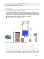
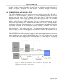
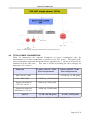
An overview of the instrument and its APEX interfaces is shown in in Figure 1.1.
2 MECHANICAL INTERFACE
2.1
CRYOSTAT AND OPTICAL FRAME
Supercam will install to the APEX standard mounting ring (the invar ring) at the top of the
Cassegrain Cabin (C-cabin). While a floor support is shown in current drawings, it does not
provide significant structural support. The baseline development plan leaves the LABOCA
M3 mirror in place and undisturbed; a protective table will be installed over the mirror to
help support the cryostat during installation and can support the instrument support
electronics during operation. The baseline plan also permits manual operation of the A/B/C
cabin swing arm assembly at zenith only and under physical supervision, as at least one
Supercam mechanical support must be removed to allow the arm to swing into position.
Utilization of the A-cabin will be explicitly supported in November, and B-cabin operation
can be supported beyond that timescale if requirements are requested well in advance.
Design Principles
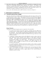
The Supercam mechanical support system is comprised of four assemblies:
1. An octopod open structure using fixed supports, extending from the APEX invar
mounting ring to a smaller-diameter Secondary Mounting Ring that directly supports
the instrument. This Secondary Mounting Ring decouples the location of dewar
supports from mounting points available on the APEX invar ring, as the two are not
naturally coincident.
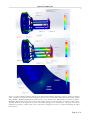
2. A substantial U-shaped support structure that holds the cryostat in place using four
main supports that allow operation of the APEX A/C cabin optical swing arm
assembly. These supports provide distributed support to the Supercam secondary
ring and crucial rigidity at all zenith angles. One support can be removed for
installation of the instrument and for operation of the APEX swing arm. The
removable support will only be removed at the stow position and only for brief
operation of the swing-arm.
3. An extruded aluminum subframe that directly attaches to the cryostat to provide
mounts for all Supercam optical elements (sky beam reimaging lens, Local Oscillator
(LO) imaging lenses, LO mount).
4. An M3 Protection Table to be initially installed to allow work on Supercam without
impact to the LABOCA M3 mirror. It will also be used for mounting of the
Supercam IF system and to provide staging support for the cryostat during its
installation into the U-mount.
Page 5 of 32