1
THE SUPERCAM ARRAY AT APEX:
INTERFACE CONTROL DOCUMENT
Version 2.0
12 October 2014
Supercam at APEX: ICD
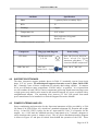
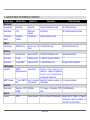
VERSION HISTORY
Version #
1.0
1.1
Implemented
By
Craig Kulesa
Craig Kulesa
Revision
Date
16 July 2014
17 July 2014
1.2
Craig Kulesa
31 July 2014
1.3
Craig Kulesa
31 July 2014
1.4
Craig Kulesa
4 Aug 2014
1.5
Craig Kulesa
24 Aug 2014
1.6
Craig Kulesa
7 Sept 2014
1.7
Craig Kulesa
19 Sept 2014
2.0
Craig Kulesa
12 Oct 2014
Approved
By
Approval
Date
Description of Changes
First complete draft
1. Typographic edits
2. Added 10 MHz reference
3. Added timing interfaces
1. First draft of changes
reflecting discussion at site visit,
up to Software Section.
1. Added brief section on UPS
2. ARTEMIS helium lines
1. Edited software section based
on 31 July discussion
2. Edited Figure 1.1 to eliminate
Arizona A-cabin pickoff
3. Edited roles per discussion
4. Numerous small edits
1. CTI compressor is actually
single phase (all 3 phases go
into the compressor but one leg
is unused internally).
2. First edit of software section
based on initial email discussion
w/ Dirk Muders.
1. Updated mechanical section
including ICD and C-cabin
installations (some
contributions from Ruben and
Paul).
1. Updated mechanical section
with integrated FEA and thread
analysis (RD and CK)
2. Updated electrical section
including documentation of UPS
module, power distribution and
control, and transformer. (CK)
3. Updated software section,
command and control, data
calibration and processing. (CK
and BP)
Minor tweaks following
discussions. Completed
summary table of interface
descriptions. FINAL DRAFT.
Page 2 of 32
Supercam at APEX: ICD
TABLE OF CONTENTS
1 - OVERVIEW..................................................................................................................................4
1.1 - Scope and Purpose of This Document..................................................................................4
1.2 - Description of Instrument Package...................................................................................... 4
2 - MECHANICAL INTERFACE.................................................................................................... 5
2.1 - Cryostat and Optical Frame..................................................................................................5
2.2 - Compressors and Helium Lines......................................................................................... 10
2.3 - Support Electronics Rack................................................................................................... 12
2.4 - Total Installed Weight Into C-Cabin...................................................................................13
3 - OPTICAL INTERFACES..........................................................................................................13
3.1 - Operation of Swing Arm for A-Cabin and B-Cabin...........................................................13
3.2 - Two-Position Calibration Load.......................................................................................... 14
3.3 - Cold Calibrations................................................................................................................14
3.4 - Sky beam Optical Relay..................................................................................................... 15
4 - ELECTRICAL INTERFACES................................................................................................. 15
4.1 - Compressors & Transformers.............................................................................................15
4.2 - Support Electronics............................................................................................................ 16
4.3 - Power Filtering and UPS....................................................................................................16
4.4 - Total Power Consumption.................................................................................................. 18
5 - RF INTERFACES.......................................................................................................................19
5.1 - 10 MHz Reference..............................................................................................................19
5.2 - Synthesizers........................................................................................................................19
5.3 - IF Outputs and the “Supercam Fiducial Pixel”.................................................................. 19
6 - TIMING INTERFACES............................................................................................................ 20
6.1 - Synchronization and Blanking Signals...............................................................................20
6.2 - NTP Time Reference.......................................................................................................... 20
7 - SOFTWARE INTERFACES..................................................................................................... 20
7.1 - Instrument Command and Control..................................................................................... 20
7.1.1 - Low Level Instrument Control................................................................................ 20
7.1.2 - Supercam’s Command and Control Interface to APECS........................................22
7.2 - Supported Observing Modes.............................................................................................. 23
7.3 - Data Flow and Archiving................................................................................................... 24
7.3.1 - Fiducial Single Pixel Interface................................................................................ 24
7.3.2 - Supercam FFTS data............................................................................................... 24
7.4 - Network Interfaces............................................................................................................. 26
8 - PERSONNEL INTERFACES................................................................................................... 26
8.1 - APEX Staff......................................................................................................................... 27
8.2 - Supercam Instrument Team................................................................................................ 27
Page 3 of 32
Supercam at APEX: ICD
8.3 - Observing Run Principal Investigators...............................................................................28
9 - MASTER TABLE OF INTERFACE CONTROLS.................................................................29
1
OVERVIEW
1.1
SCOPE AND PURPOSE OF THIS DOCUMENT
This ICD aims to document and track the information required to define the Supercam system
interface to the APEX telescope. It will relate inputs and outputs from Supercam for all
potential actions. This will give all parties guidance on the architecture of the system to be
integrated in November 2014, and help ensure compatibility between system components. A
Q emblem identifies critical questions that still needs to be addressed.
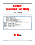
1.2
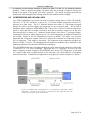
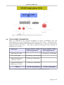
DESCRIPTION OF INSTRUMENT PACKAGE
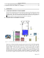
Figure 1.1: Overall block diagram of the Supercam instrument on APEX
Supercam is a 64-beam heterodyne array that operates between 300 and 400 GHz, though the
power output of the current Local Oscillator (LO) restricts this range to 330-365 GHz. The
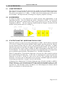
baseline operating mode will observe the 12CO J=3-2 line at 345.795 GHz in the upper
sideband (USB). The focal plane is comprised of eight integrated blocks each with 8
feedhorns, mixers and low noise amplifiers (LNAs), cooled to ~5K through a GiffordsMcMahon (GM) closed cycle cryocooler. 64 stainless-steel coaxial cables bring out the
mixer IFs and are precooled to 15K with a second GM cryocooler. The 4-6 GHz IF outputs
are passed first to IF processor modules and then to a digital FFT spectrometer. The IF
processor filters, amplifies, and downconverts the 5 GHz IF to baseband. Bias voltages for
Page 4 of 32
Supercam at APEX: ICD
each mixer’s SIS device, electromagnet, and LNA are provided by 8-channel bias cards
mounted in a half-height rackmount chassis adjacent to the cryostat. All voltages in the
cryostat are monitored by the bias cards’ macrocontrollers; isolation and noise reduction for
returning signals is provided by a preamplifier between the bias cards and the cryostat. The
instrument is remotely controlled via TCP socket servers over ethernet.
An overview of the instrument and its APEX interfaces is shown in in Figure 1.1.
2 MECHANICAL INTERFACE
2.1
CRYOSTAT AND OPTICAL FRAME
Supercam will install to the APEX standard mounting ring (the invar ring) at the top of the
Cassegrain Cabin (C-cabin). While a floor support is shown in current drawings, it does not
provide significant structural support. The baseline development plan leaves the LABOCA
M3 mirror in place and undisturbed; a protective table will be installed over the mirror to
help support the cryostat during installation and can support the instrument support
electronics during operation. The baseline plan also permits manual operation of the A/B/C
cabin swing arm assembly at zenith only and under physical supervision, as at least one
Supercam mechanical support must be removed to allow the arm to swing into position.
Utilization of the A-cabin will be explicitly supported in November, and B-cabin operation
can be supported beyond that timescale if requirements are requested well in advance.
Design Principles
The Supercam mechanical support system is comprised of four assemblies:
1. An octopod open structure using fixed supports, extending from the APEX invar
mounting ring to a smaller-diameter Secondary Mounting Ring that directly supports
the instrument. This Secondary Mounting Ring decouples the location of dewar
supports from mounting points available on the APEX invar ring, as the two are not
naturally coincident.
2. A substantial U-shaped support structure that holds the cryostat in place using four
main supports that allow operation of the APEX A/C cabin optical swing arm
assembly. These supports provide distributed support to the Supercam secondary
ring and crucial rigidity at all zenith angles. One support can be removed for
installation of the instrument and for operation of the APEX swing arm. The
removable support will only be removed at the stow position and only for brief
operation of the swing-arm.
3. An extruded aluminum subframe that directly attaches to the cryostat to provide
mounts for all Supercam optical elements (sky beam reimaging lens, Local Oscillator
(LO) imaging lenses, LO mount).
4. An M3 Protection Table to be initially installed to allow work on Supercam without
impact to the LABOCA M3 mirror. It will also be used for mounting of the
Supercam IF system and to provide staging support for the cryostat during its
installation into the U-mount.
Page 5 of 32
Supercam at APEX: ICD
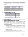
Figure 2.1: Diagram of Supercam installed into the APEX C-cabin. The cryostat is supported from above
via the U-mount and Secondary Mounting Ring, and its supporting electronics are attached to the floor.
Figure 2.2: Cut-away of Supercam in the APEX C-cabin, showing the APEX swing arm in the A-cabin (left) and
C-cabin (right) positions. A single vertical support is removed from the Supercam mount to allow the arm to be
operated, then reinstalled once the swing arm is in place.
Page 6 of 32
Supercam at APEX: ICD
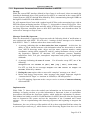
Design Loads, Limits, and Structural Analysis
FEA and fastener analysis was performed on the Supercam mechanical assembly to assess
structural integrity. In response to Action Item 009 from Michael Cantzler, “After review of
antenna documentation and consultation of Vertex Duisburg, the design limits shall be
defined by the estimated worst case accelerations of an earthquake scenario.
The
corresponding values are given in the table below.”
Direction
Acceleration (g)
Safety Factor
Design Limit (g)
Vertical
1.80
2.0
3.60
Horizontal
1.15
2.0
2.30
Table 2.1: Defined load limits per AI0009
Because the allowable bending of the structure is most stringently defined by the optical
tolerancing, it very naturally provides a very high degree of safety in overall integrity. The
FEA analysis begins at the invar ring, assuming that it is fixed, and determines the stresses
and deflections of the Supercam structure from gravity at two elevation angles; zenith and
horizon. The worst-case deflections are naturally present when pointed at the horizon (Figure
2.4). The deflections and structural safety factors assuming A500, A36 structural steel for
the entire assembly and are shown in Table 2.2
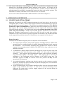
Figure 2.3: Finite Element Analysis (FEA) of the Supercam mechanical mounting structure when pointed
at zenith. (left) von Mises stress plot shows that the highest stress is at the octopod tubes attached to the
Secondary Support Ring. (right) Maximum displacement of the structure is less than 0.1 mm. Safety factors
exceed 20 everywhere.
Page 7 of 32
Supercam at APEX: ICD
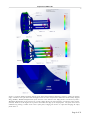
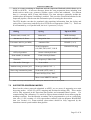
Figure 2.4: Finite Element Analysis (FEA) of the Supercam mechanical mounting structure, pointed at horizon.
(top): von Mises stress plot shows that the highest stress is at the octopod tubes attached to the Secondary Support
Ring. (middle): Maximum displacement of the structure is less than 0.1 mm. Safety factors exceed 20 everywhere.
Maximum displacement of the structure is 0.2 mm. Safety factors for both structures exceed 20 in most regions.
(bottom): Zoom-in on the highest stress point in the model; the edge of an octopod plate. The point stress can be
eliminated by placing a radius at the corner of the plate, bringing the stresses to 3 kpsi and bringing the safety
factor above 5.
Page 8 of 32
Supercam at APEX: ICD
The main structural limitation of the Supercam mechanical assembly is not the main structure
itself, which is clearly designed to the much more stringent optical tolerances. Rather, it is
the thread strength of the fasteners which is the limiting factor.
The cryostat is supported with 4 x 3/4”-16 bolts to the four vertical cryostat supports, with Lbrackets and ¼-20 bolts providing additional support at the top of the cryostat. The vertical
members are attached with a T-interface to the Secondary Support Ring using 6 x 3/8” bolts
each (24 total). The 8 octopod supports mount with 4 x 3/8” bolts to the Secondary Support
Ring and to the Invar Ring with 13 x M12 bolts.
Maximum Deflection
0.1 mm at zenith
0.2 mm at horizon
Maximum stress
Up to 1.6 kpsi
Up to 5 kpsi horizon*
>20 zenith
>6 horizon
Table 2.2: Summary of load analysis of main structural members.
Bolt set
Safety Factor
Thread strength
*
See Figure 2.4 for details.
Max Load
Safety Margin
Lower Cryostat 4 x 3/4”
20000 lb ea
160 lb ea
100
Upper Cryostat 16x3/8”
3600 lb ea
50 lb ea
75
Lower Ring 32x3/8”
3600 lb ea
25 lb ea
150
Upper Ring 13xM12
7200 lb ea
75 lb ea
100
Table 2.3: Fastener analysis assuming uniform load distribution at ZENITH.
Bolt set
Thread stress
limit
Max stress
Safety
Margin
Lower Cryostat 4 x 3/4”
30 kpsi
2 kpsi
15
Upper Cryostat 24x3/8”
30 kpsi
3 kpsi
10
Lower Ring 32x3/8”
30 kpsi
8 kpsi no clamps
4 kpsi clamped
3.75
7.5
Upper Ring 13xM12
30 kpsi
10 kpsi no clamps
5 kpsi clamped
3
6
Table 2.4: Fastener analysis assuming asymmetric load distribution at HORIZON. These loadings are based
on the direct moment arm calculation and upon the FEA stresses at specific points in the structure. To improve
safety margin at the invar ring, clamp fixtures will be added to the invar ring, between the M12 bolts, to reduce
the tension load and eliminate any possibility of thread stripping or shearing.
Page 9 of 32
Supercam at APEX: ICD
A summary of the fastener analysis is shown in Table 2.2 and 2.3 for zenith & horizon
pointing. Grade 5 imperial and grade 9.8 metric bolts are assumed for analysis, though we
intend to use grade 8 and grade 10.9 where possible. The thread strength conservatively
assumes the yield strength as the starting point, not the ultimate tensile strength.
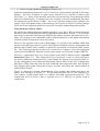
2.2
COMPRESSORS AND HELIUM LINES
Two Gifford-McMahon cryocoolers are used to provide cooling stages at 50K, 15K and 4K.
The first, a CTI-350 cold head, is driven by a CTI-8200 helium compressor located at a
distance up to 20m away. Two 0.5” diameter helium lines with 0.5” self-sealing Aeroquip
fittings are used to provide supply and return gas to the cryocooler head. The second, a
Sumitomo Heavy Industries (SHI) RDK-415D, is driven by a CNA-61C helium compressor,
which is itself split into an indoor electronics unit and an outdoor compressor & fan unit.
Each module has 10 meters of 1” diameter helium transfer line with 0.5” Aeroquip fittings,
combining to 20 meters. Both compressors are air-cooled and require no additional interfaces
for cooling. Based on the low atmospheric pressure at APEX (~525 mbar), care must be
taken that the compressor outdoor unit not be subjected to ambient air temperatures above
20C for operation. This implies a sun shade. The footprints of the compressor modules are
shown in Table 2.5 below. We anticipate that all compressor modules can be installed on the
instrument platform near the other APEX heat exchangers.
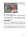
The ARTEMIS helium lines extending through the cable wrap from the compressor loft to the
C-cabin use 3/4” (-12 series) couplings. Supercam uses 1/2” couplings (-8 series). We will
make 4 adapters to allow mating to the ARTEMIS lines for the CTI compressor: a stub with
1/2" female (5400-S5-8) coupling brazed on one side and a 3/4" male (5400-S2-12) coupling
brazed on the other. Helium line arrangement to be deployed is shown in Figure 2.5 below.
Figure 2.5: Helium line arrangement to be baselined for Supercam's APEX
integration. Portions in green must be purchased by the Supercam team; the
orange portion represents the Artemis lines.
Page 10 of 32
Supercam at APEX: ICD
Compressor
Unit
Dimensions
(cm)
Weight
(kg)
Power
Environment
CNA-61C
“indoor”
63 x 27 x 57
45
208V 3Φ @40A
8.0 kW / 50 Hz
9.2 kW / 60 Hz
5C to 35C
CNA-61C
“outdoor”
91 x 103 x 39
115
From indoor unit
-30C to 45C
CTI-8200
51 x 43 x 57
70
230V 1Φ @10A
2.1 kW rms
0C to 40C
Table 2.5: Supercam helium compressor specifications
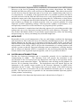
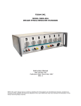
Figure 2.6:
Conceptual diagram of an
isolation mount for Supercam's
compressors. Sandwiched
between two aluminum plates
is a soft rubber plug with 1/420 threaded center. Ratchettype hooks will tie into the
grating floor on the instrument
platform.
Facility UHP helium should be available to charge compressors and helium lines. The static
pressure for the CTI-8200 is 1.7 MPa (250 psi) and the CNA-61C is 1.65 MPa (245 psi).
Page 11 of 32
Supercam at APEX: ICD
Figure 2.7: Diagram showing the C-cabin tie-downs and routing pattern of Supercam’s Sumitomo helium lines.
The right hand drawing shows the clearance of the helium lines through the MKIDS instrument area.
Constraining the helium lines in the B-cabin remains a work in progress and a detailed model of the B-cabin
installation is required.
2.3
SUPPORT ELECTRONICS RACK
Figure 2.8: (Left): Overhead diagram of Supercam electronics installation options atop or adjacent to the M3
protection table. (Right): Conceptual structural support for electronics rack when horizon pointing (full
triangular brace and correct dimensioning is underway).
All of the electronics needed to operate Supercam are to be installed in the C-cabin in close
proximity to the cryostat. The M3 Protection Table will house the IF and FFTS system in
open-frame server racks on the ARTEMIS side of the cryostat (Figure 2.5-left). The DC
electronics will be mounted in the current 18U half-height rack and mount the LO
distribution box, FFTS and IF processor on the table.
Page 12 of 32
Supercam at APEX: ICD
Because of its significant weight, the support electronics rack needs additional anchoring for
horizontal-pointing. This support comes in the form of triangular metal braces that attach to
the floor (Figure 2.5-right). Weights and dimensions of the three modules are shown below
in Table 2.3.
Electronics Module
Dimensions (cm)
Weight
50 x 60 x 100
130 kg
IF processor
45 x 45 x 60
40 kg
FFT spectrometer
50 x 40 x 15
10 kg
Support electronics rack
Table 2.6: Specifications for the three electronics modules to be installed in the C-cabin
2.4
TOTAL INSTALLED WEIGHT INTO C-CABIN
Module
Weight (kg)
Cryostat + U-mount + Optics Subsystem
420
Support Electronics Modules
180
TOTAL
600
Table 2.7: Total weight installed into C-cabin.
3 OPTICAL INTERFACES
3.1
OPERATION OF SWING ARM FOR A-CABIN AND B-CABIN
During poorer summer weather at APEX, it may be necessary to switch to the 230 GHz
receiver (SHFI’s APEX-1) in the A-cabin. We have baselined a mechanical structure that can
support operation of the APEX optical swing-arm assembly with the temporary removal of
one structural member of the Supercam mount. Automatic operation of the swing arm
must be disabled; it must only be done at stow and under direct, manual control. The
nominal procedure is expected to be:
1. Stow telescope and remove one (A-cabin) or both (B-cabin) removable Supercam
vertical truss supports. Use of the swing arm also requires removal of the Supercam
LO beamsplitter and sky lens mounts and should only be done by Supercam
personnel. B-cabin operation is not being supported for the Novermber/December
2014 run but can be discussed for a hypothetical second run if it materializes.
2. Remove beamsplitter mount and upper Supercam lens.
3. Move swing arm into position.
4. Reinstall Supercam vertical support and unstow telescope for operation.
Figure 2.2 illustrates the setup for A-cabin and C-cabin modes and Figure 3.1 shows the Acabin mirror in position from the top.
Page 13 of 32
Supercam at APEX: ICD
Figure 3.1: Illustration of the
A-cabin swing arm in
position, surrounded by the 4
vertical Supercam cryostat
supports.
3.2
TWO-POSITION CALIBRATION LOAD
A rotary stepper motor actuator will be used to insert an aluminum disk lined with multiple
layers of eccosorb AN-72 into the beam for calibration-wheel calibration of the temperature
scale.
Calibrations will be performed at regular intervals, typically every few minutes
depending on the variability of the atmosphere. The actuator will flip between two fixed
positions and the absolute position of the disk will be verified through the use of an internal
encoder, indexer position, and registration of the disk by magnetic Hall-effect sensors at the
clockwise and counter-clockwise limits. The (blackbody) temperature of the load will be
continuously monitored for calibration.
3.3
COLD CALIBRATIONS
At the HHT, manual cold calibrations using a two-layer ~20x20 cm paddle of LN 2-soaked
eccosorb AN-72 are performed whenever the receiver is re-tuned or otherwise about 2-3
times daily. At APEX, it is expected that Supercam will spend nearly all of its time at the
supported 12CO 3-2 frequency (345.795 GHz). Other frequencies will be tested in the lab by
request. Currently the 13CO J=3-2 line at 330 GHz is the only other known requirement for
December 2014. As it may involve a change in hardware and requires cold-calibration,
switching spectral lines can only be done when personnel are on-site.
To facilitate manual cold calibrations, the facilitator will need to bring a laptop computer into
the cabin with a cold-load software application running. The Cold Load application will
listen to APECS for signals to perform a Hot/Cold/Sky calibration and will advise the
facilitator to insert the cold load into position, prompt when the load is in position, and advise
when the load should be removed.
Page 14 of 32
Supercam at APEX: ICD
3.4
SKY BEAM OPTICAL RELAY
The f/8 beam directly arriving from the APEX secondary will be relayed to the Supercam
focal plane by two anti-reflection coated lenses. Because the cryostat was lowered to allow
use of the swing arm, the lower lens can no longer be used as a replacement for the cryostat
window. It now resides atop the beamsplitter mount. UHMW polyethylene will be used as
the lens material and the AR coating will be an 8-mil thick sheet of Zitex G108 (45% pore
volume) with thin LDPE film to be heated as the ‘glue’ layer. The master reference for
coating HDPE with Zitex is Hargrave & Savini, 2010, Proc SPIE, 7741 (Cardiff group).
http://loke.as.arizona.edu/~ckulesa/binaries/supercam/optics/Hargrave_AR_Coat_HDPE.pdf
The
combination of absorptive and reflective losses is not expected to exceed 8% in either lens
and while slightly lossier than a reflective system, will provide the very simplest optomechanical interface to the APEX telescope.
Figure 3.2: Zemax
rendering of
Supercam optical
re l a y f ro m f / 8
Cassegrain focus
to f/5 focal plane.
4 ELECTRICAL INTERFACES
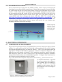
4.1
COMPRESSORS & TRANSFORMERS
The electrical requirements for the CTI and SHI GM cryocooler compressor units are shown
in Table 2.1; a total of 50A at 208 VAC, 50/60 Hz, 3-phase and about 15A at 230V 1-phase.
The currently-adopted plug types are shown in Table 4.1. The CTI can be operated from the
single phase 230VAC 50 Hz with the appropriate switches set inside the compressor. The
Supercam team will identify an isolated 15 kVA transformer needed to supply Supercam’s
SHI compressor with 50 Hz 208V 3-phase power. The transformer should be installed in
advance of the 22 November start of installation if possible. If shipped from North America,
the following isolation transformer may be selected:
http://www.temcoindustrialpower.com/products/Transformers_-_General/T46078.html
An isolation transformer is specified
for safety: to ensure that a failure in
either winding does not transfer to
the other, or that an overvoltage
condition in the primary does not
auto-transform to an overvoltage in
the secondary.
Figure 4.1: Isolation transformer selected for Supercam's
Sumitomo compressor if shipped from North America.
Page 15 of 32
Supercam at APEX: ICD
Attribute
Specification
Phase
3 (primary Delta, secondary Wye)
KVA
15
Windings
Copper
Temperature rise
115C or less
Mechanical
Steel enclosure, 86 kg total
40x60x55 cm
Table 4.1: Isolation transformer specifications
Compressor
Plug type and diagram
CTI-8200
NEMA twist lock
L21-20
SHI CNA-61C
IEC 309
3 pole+N+G = 5 pin
Power rating
20A, 3Ф (Y or Δ), 208 VAC
Note: wired for North
American split-phase; 3 rd leg
is unwired inside compressor!
60A, 3Ф Y, 208 VAC
Table 4.2: Compressor plug types currently used in Supercam
4.2
SUPPORT ELECTRONICS
The three electronics support modules shown in Table 2.2 nominally operate from single
phase 115V AC power. We will adapt all support electronics to use 1 phase, 50 Hz 230V
AC. Naturally, some of these components are already dual-voltage capable. In summer
2014, we will make as many components “230VAC-native” as possible. It is expected that
we will combine all such 230VAC-native components (still using North American plugs) onto
a single power strip which can be mated to the normal European AC power receptacle with a
straightforward adapter. The remaining (few) items at 115 VAC will operate from small
power transformers to be installed in or near the Support Electronics Module.
4.3
POWER FILTERING AND UPS
Power conditioning and protection for the Supercam instrument will be provided by a 1500
VA Eaton 9130 UPS (Figure 4.2), which has a standard rackmount 2U footprint and weighs
20 kg. It has IEC-320-C14 plugs for the AC input and IEC-320-C13 receptacles for the
outputs. At a 1 kW load, the standard run time is anticipated to be 7 minutes; adequate to
safely shut down the system (1 minute or less). The AC power distribution interface diagram
is shown in Figure 4.3 and puts all critical items behind the operation of the UPS. These
Page 16 of 32
Supercam at APEX: ICD
items are also under direct power control of an ethernet-controlled 8-port AC power
distribution box which allows independent subsystems to be turned on and off remotely. This
will allow the system to be powered down in a controlled fashion in the event of power loss.
It further allows the system to be brought up remotely in a controlled fashion. The Supercam
UPS will be programmed to power up after a power loss only once the batteries are recharged
or under manual intervention.
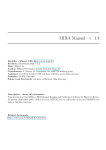
Figure 4.2: (top) UPS system selected for Supercam electronics is a 2U rackmount system with 230VAC
capability and a remote, managed interface. Only the top 2U unit will be used; the bottom module in the
figure is an add-on battery module for extended runtime. (bottom) The back face shows the connectors
needed to interface with the APEX power system. Schuko to IEC cable adapters are baselined.
Page 17 of 32
Supercam at APEX: ICD
Figure 4.3: Block diagram of power distribution system for Supercam.
4.4
TOTAL POWER CONSUMPTION
Table 4.2 summarizes the expected breakdown of power consumption after the
transformation of as many components as possible to 230 VAC power. The listed “peak”
power consumption represents the inrush current, applicable for << 100 ms, if all devices are
switched on at the same time.
This value is useful for defining the (fuse) rating(s) for
Supercam’s AC circuit(s).
Subsystem
SHI CNA-61C (4K)
CTI – 8200 (15K)
Support electronics #1
(230 VAC “native”)
Support electronics #2
(Transform to 115 VAC)
TOTAL
1 phase, 230 VAC, 50 Hz
Power Requirements
-
3 phase, 208 VAC, 50 Hz
Power Requirements
8.2 kW avg (11 kW peak)
2.1 kW avg (2.8 kW peak)
500W avg (700W peak)
-
900W avg (1500W peak)
-
3.5 kW (5.0 kW peak)
8.2 kW (11 kW peak)
Table 4.3: Overall breakdown of Supercam's power consumption, including transformer losses.
Page 18 of 32
Supercam at APEX: ICD
5 RF INTERFACES
5.1
10 MHZ REFERENCE
The Supercam LO system and the downconverter module for the 64-channel IF processor
both require a 10 MHz reference source, to be provided by the facility’s GPS station clock.
The power level required is 6-13 dBm. 7.5 dBm is the current measurement of the power
level available. The Supercam team will bring a low frequency amplifier as backup.
5.2
SYNTHESIZERS
As shown in Figure 5.1, the Supercam LO system operates fully independently of the
supporting telescope. We will continue this mode of operation at APEX. For successful
operation, the Supercam Command and Control system needs access to the sky frequency
computed by APECS. The sky frequency should include the Doppler correction for the
antenna velocity and the observer’s catalog V LSR.
Figure 5.1: Block diagram of Supercam LO subsystem.
5.3
IF OUTPUTS AND THE “SUPERCAM FIDUCIAL PIXEL”
Supercam performs its own IF processing independent of APEX. The IF chain is comprised
of a series of 8-channel IF Processor modules which amplify and filter the 64 IFs from the
cryostat, downconverting from 4-6 GHz to the baseband signal (0-500 MHz, -10 dBm)
required at the input of a 16 GHz wide digital FFT spectrometer (FFTS). 64 output IFs are
power-combined into 32 FFTS inputs, yielding 256 MHz of bandwidth per Supercam “pixel”
in 1024 channels. In reality, the edges of the spectra are trimmed because of overlap in the
power-combined region (typically ~900 channels over ~240 MHz of bandwidth).
While IF independence is important for Supercam, it increases the effort needed to perform
basic commissioning and observing. To this end, it is advantageous to split one pixel from
Supercam to provide a “facility IF” that can be used for basic pointing and focusing
operations. In essence, this so-called fiducial pixel presents a standard single pixel interface
so that Supercam looks like a “normal” receiver to the facility.
A diagram of the “fiducial pixel” IF that the Supercam team will make available to APEX is
shown in Figure 5.2. We will supply the broadest IF possible but degradation above 7.5 GHz
is likely. The output power can be as high as -35 dBm and can be manually attenuated to any
required level. We notionally assume -50 dBm in a 4-6 GHz bandpass as a default, with an
option to run filterless or with a broader filter.
Page 19 of 32
Supercam at APEX: ICD
Figure 5.2: Block diagram of Supercam’s generic single-pixel (a.k.a. ‘fiducial') interface to the
APEX facility IF system.
6 TIMING INTERFACES
6.1
SYNCHRONIZATION AND BLANKING SIGNALS
For beam-switched observations, external synchronization and blanking signals are needed.
The SYNC signal defines the phase for the beam-switched integration (secondary nutation
left or right), and the BLANKING signal is used to mask out the transition time. The
Supercam FFTS requires a minimum 40 msec blanking time; 50 msec is preferred. We
understand that the delayed blanking signals from APEX are to be used for this specification.
We ask to not nutate the subreflector faster than 2 Hz; 1 Hz is ideal. These signals are
brought into the Supercam FFTS over BNC-terminated coax cables from the facility D-sub
connector.
Q The pinout specification and cable length are required.
6.2
NTP TIME REFERENCE
The Supercam data acquisition PC needs to have access to an NTP time server to serve as a
time reference. Q What is the IP address or name of the nearest time server?
7 SOFTWARE INTERFACES
7.1
INSTRUMENT COMMAND AND CONTROL
7.1.1
Low Level Instrument Control
The overall software layout for Supercam as anticipated for APEX is diagrammed in
Figure 7.1. The Supercam instrument hardware is controlled by a series of TCP socket servers
operating from embedded ARM macrocontrollers (supercam1-8), and the Data Acquisition
computer (supercam9) in the Support Electronics Rack. These hardware servers are:
•
biasServer: runs on all 8 Supercam macrocontrollers and controls the bias electronics
cards that supply SIS, electromagnet, and LNA bias voltages to the cryostat.
BiasServer also can monitor any of the sensed voltages in the cryostat. Supercam8
also is wired to handle the synthesizer function that sets the sky frequency for the LO.
•
blankServer: runs on supercam1 and provides the ‘integrate’ TTL signal to the
Omnisys FFT spectrometer that is used for OTF mapping. This signal is locally
generated by blankServer or is switched to an external TTL “blanking” input from the
secondary (for beam-switched observations), and logically inverted as needed.
Page 20 of 32
Supercam at APEX: ICD
•
cryoMon: runs on supercam8 and provides an interface to the Lakeshore 208
temperature monitor that reads the DT470 silicon diodes inside the cryostat.
Basic communication with these servers can be done interactively from the command line via
telnet or netcat to a particular server, interactively by GUI, or non-interactively via higher
level scripts or programs. Supercam is to be operated through a series of single-purpose
scripts which can be invoked through a master GUI. Engineering level GUIs for single-pixel
adjustments will be provided, and monitoring of the instrument through the master GUI or a
remote web page is the expected mode of operation at APEX.
However, all observing sequences operate through higher level ‘glue logic’ interfaces that
monitor the state of the telescope and observing, and keep Supercam’s operation in sync.
This logic is held within SuperComm, the recipient of observing messages from the HHT.
Using an orchestral analogy, SuperComm acts as the central conductor who keeps the various
socket servers playing on-time and in-tune. Its sidekick, Monitor, harvests information from
the various socket servers to maintain knowledge of the current state of the instrument.
In its software implementation for the HHT, Supercam is passive to the underlying telescope
control system; it only receives messages and never sends commands. It only sends
unsolicited messages to the log system when it is having difficulties and wants to notify the
cognizant observer or telescope operator. We anticipate the same interface at APEX.
Figure 7.1: Block diagram of Supercam's command and control system, from hardware to APECS interface.
Page 21 of 32
Supercam at APEX: ICD
7.1.2 Supercam’s Command and Control Interface to APECS
Strategy
While the current HHT interface defined in SuperComm is well tested, it does not match the
formalized distributed object (DO) model used at APEX, as canonized in the current APEX
Control System (APECS), through DOs defined by IDLs, communicating through CORBA at
the high level and SCPI at the hardware level.
We will augment SuperComm with a python-based SCPI-to-socket messaging layer with an
HHT-like output messaging interface. In Figure 7.1, this module is shown as apex2hht. Here,
we leave SuperComm mostly intact and only add a SCPI layer to scan for APEX messages
involving Supercam, transform them to their HHT equivalents, and rebroadcast them via
socket server messages to SuperComm.
Messages Needed By Supercam
When an observation is requested, Supercam needs the following kinds of notifications to
stay synchronized with APEX. We will seek 1:1 analogs of these messages to be obtained
from APECS. Table 7.1 indicates where these items can be found.
1. A message indicating that an observation has been requested. At this time, the
ability to fill an internal structure with information about the observation is needed
from APECS: observing mode, object and line name, sequence number, catalog
coordinates, catalog offsets, antenna EL and AZ, catalog & antenna velocity, rest and
sky frequencies, sideband, UT date/time, LST, temperature, pressure, humidity,
subreflector focus, Tcal, pwv, atmospheric temperature and opacity in signal/image
sidebands.
2. A message indicating the start of a scan.
following:
For all modes except OTF, one of the
Integrate for <x> seconds on {SIG | REF | Sky | Vane | Cold Load}
For OTF, we look for two messages: Prepare for OTF raster of length <x>
seconds, followed by a Start.
3. Ending the scan requires either a successful “complete” message or an “abort”.
4. Before and during observations, other messages that impact Supercam might be
“Antenna On/Off Target” or “Antenna in +BEAM (or -BEAM) position”.
5. For OTF mapping, Supercam needs a way to receive a stream of antenna telemetry
of RA and DEC.
Implementation
While Table 7.1 shows where the needed scan information can be harvested, the highest
challenge is figuring out how to get this information to Supercam in time to synchronize
observations and inform the Supercam pipeline, which wants this information in advance.
Dirk Muders has kindly provided a Virtual Machine for APECS that will allow the Supercam
team to characterize the system and test the integration of the Command and Control
software. We are experimenting with observing sequences and beginning to integrate the
system.
Furthermore, the core of the apex2hht module will be a short script that Dirk has written for
us (monitorSupercamScans.py), which listens to the Observing Engine from observer3 and
Page 22 of 32
Supercam at APEX: ICD
reacts to events pertaining to Supercam and the Supercam Backend (which shows up as
SCBE in APECS). It harvests messages about the scan preparation phase including scan
details such as mode, type, geometry, wobbler, source, offset, and command. Per subscan
there is a message when it starts and finishes. The start messages optionally include the
wobbler phase description if wobbling is enabled. This provides essential information for the
Supercam pipeline, which wants this information prior to starting the observation.
The FITS headers can then be populated with remaining information from the obslog and
syslog files (if necessary) and the top level FITS files as appropriate (Table 7.1). These can
be accumulated by, or in parallel with, the level 1 processor (scarfer).
Obslog
Source name, coords, vel
Syslog
Top level FITS
Subscan #
MJD timestanp
Antenna az, el, focus
Integration time
LONGOFF, LATOFF
Line name and freq (to MHz)
Antenna offset
PHASE (1 or 2)
Source offsets
OFF (ref) position
Scan number, # subscans
Scan time
Obs mode / Scan type
Scan Designation
ON, REF, SKY, HOT, COLD
PARANGLE (deg)
Source velocity & frame
Earth velocity & frame
Sky frequency LSB & USB
Scan number
Ambient temp, pressure, pwv
Scan type (MAP, CAL ...)
Observing command w/parms
Scan mode (OTF, raster...)
Last CAL Tsys, Trec, Tcal...
Most recent MBFITS subscan
Table 7.1: List of scan information available from APECS and where it can be found.
7.2
SUPPORTED OBSERVING MODES
Based on the science proposals submitted to APEX, we are aware of supporting two main
observing modes: On the Fly (OTF) mapping and Position-Switching (PS). These modes
will be fully supported in the Supercam data pipeline and command/control system. For
commissioning and calibration, it is useful to support beam-switched observations using the
nodding secondary. Provided that the secondary can be programmed to cycle at a sufficiently
slow rate (1-2 Hz, creating a 2-4 Hz spectrometer cadence) with an adequate BLANKING
time (see Section 6.1), beam-switched observations should be fully supported by the
instrument control system and the data pipeline.
Page 23 of 32
Supercam at APEX: ICD
7.3
DATA FLOW AND ARCHIVING
7.3.1 Fiducial Single Pixel Interface
Supercam can provide a single pixel IF output centered at 5 GHz and at -30 to -60 dBm to a
supported facility IF processor and backend. In this manner, one of Supercam’s pixels can
follow the expected data flow for an APEX receiver, through apexOnlineFitsWriter and
apexOnlineCalibrator and apexCalibDisplayServer. These data products will flow through
the standard APEX portals, from display2 at the summit to Sequitor and then daily through
the esodata archiving tool at the ESO data archive in Santiago and then on to ESO/Garching,
with both MBFITS and CLASS data outputs. This basic data flow is shown in Figure 7.2
and is independent of the specific handling of the 64-beam Supercam FFTS data described in
the following Section (7.3.2).
Figure 7.2: Data flow for Supercam's fiducial pixel, routed through the APEX
facility IF system to a facility spectrometer (XFFTS2 or AFFTS). These data
follow the standard flow for APEX and would provide quick-look data for one of
Supercam's IFs.
7.3.2 Supercam FFTS data
Supercam’s 64-beam spectral data are acquired independently of APEX systems and are
automatically processed through a two-stage pipeline that takes the data to flux-calibrated and
velocity-calibrated spectra. The data processing levels are defined as:
•
Level 0: Raw spectrometer bandpasses (stateless binary files).
•
Level 0.5: Raw bandpasses with header information, written as SDFITS.
•
Level 1: Calibrated spectra, in (S-R)/R format, optionally baselined, in SDFITS.
•
Level 2: Baseline-subtracted, regridded spectral line FITS cubes.
Page 24 of 32
Supercam at APEX: ICD
•
Level 3: Science products (catalogs of objects, etc.).
Supercam automatically generates Level 0.5 and Level 1 data products through its two-stage
pipeline. The Level 0 pipeline is called scooper and the Level 1 pipeline is called scarfer
(see Figure 7.1). These are not normally run by the user interactively except during the initial
phases of commissioning. In contrast, the level 2 pipeline is not run automatically but rather
run interactively by the observer offline. Two Level 2 pipeline options will be available; one
using CLASS, and another using a Supercam-specific rework of ATNF’s Gridzilla package.
These will be the supported options for science PIs using the standard Supercam pipeline.
What will be provided at APEX?
By default, the standard Supercam pipeline through Level 1 data is fully operational and can
already be used (with appropriate APECS notifications and headers, Section 7.1.2) to feed the
data archive at Sequitor with Supercam SDFITS data ready to baseline and regrid into Level 2
maps. This strategy is also compatible with the limited manpower on the Supercam team that
would be needed to implement a new data system.
However, this approach comes with a disadvantage: it is foreign to the standard APEX data
interface and archiving system. It comes with different reduction software requirements and
different data formats, and is unlikely to match the expectations of seasoned APEX science
PIs. The Supercam team does not have the resources to re-engineer a new data acquisition
system based on MBFITS, when the current system works very well with (simpler) SDFITS.
However, a compromise may serve some portions of the APEX audience better: a parallel
datastream (Figure 7.3). Here, Supercam’s Level 0 processor (scooper) will also provide a
raw binary datastream comprised of 64 x 900 channel IFs directly to apexOnlineFitsWriter.
For the configuration of the Supercam Distributed Objects (DOs) in the ACS Configuration
Data Base (CDB), hosts and ports for both commands and science data have been defined.
The backend data stream format that scooper provides will follow the format defined in
APEX-MPI-ICD-0005.
Figure 7.3 shows the expected implementation of the parallel data stream, and shows the
archive flow analogous to Figure 7.2. The uncompressed data rate for OTF mapping at a
3 Hz cadence in dual-stream mode is 12 Mbit/s and could represent the peak rate. The
compression level for level 0 data is expected to be 2:1 with gzip or greater using xz
compression.
Page 25 of 32
Supercam at APEX: ICD
Figure 7.3: Dual-channel data flow for Supercam's 64-beam FFTS data. APEX-standard MBFITS
and CLASS files will pass to ESO through the Archive, while the standard Supercam pipeline data
in SDFITS format will likely stop at Sequitor and be archived with the final survey products at
Arizona and IPAC.
7.4
NETWORK INTERFACES
Supercam’s network structure is ‘hidden’ behind a 16-port 10/100 Mbit ethernet switch,
which presents internal 192.168.1.xxx and 192.168.2.xxx subnets for instrument use. Only
supercam9, the master data acquisition computer, requires a static IP address from the APEX
network. Several IP addresses are required by the installation and commissioning team for
personal laptops via ethernet and/or 802.11. However, dynamic allocation from a pool of
addresses (e.g. DHCP) is adequate as these machines do not need to have static or stable
addresses.
8 PERSONNEL INTERFACES
It is important to establish the general roles and responsibilities and overall structure of the
work effort. In particular, here we would like to identify how the observing run is to be
performed, by whom, in order to assess the requirements for the deploying team.
Installation and commissioning is a fairly straightforward work effort that necessarily leans
heavily on the Supercam Instrument team. The overarching question is how observations will
be undertaken and how the Supercam and APEX teams will be involved in planning them,
scheduling them, carrying them out, and supporting them to publication.
Page 26 of 32
Supercam at APEX: ICD
Based on discussions, Supercam will be considered a PI instrument by the APEX facility.
However, at the level of planning and performing the science observations, the Chilean,
Swedish and ESO time will be each carried out in a Service mode. This reduces the need for
several observers from the Supercam team to be present once commissioning ends, however,
it is important for 1-2 members of the Supercam team to be available to process the data in
real time and work with the ESO and OSO observers to verify that good data are being taken
and that the target goals of the observations are being achieved. Furthermore, to best prepare
for the run, it is suggested that ESO/OSO/Chilean PIs and observers work with Supercam
team members to examine the awarded proposals, write up a general guideline for using
Supercam at APEX (submitting catalogs, observing modes, updates on performance, etc.),
and optionally contact PIs to solicit and answer any program-specific questions.
Once the instrument is commissioned and observing appears to be proceeding smoothly, then
perhaps only one or two Supercam personnel need to be at the summit or at Sequitor. The
role of these individuals would be to specifically support Supercam, follow the data taking
and processing very closely, and manage any issues that might arise.
8.1
APEX STAFF
Responsible for the overall management of the run, and helping coordinate the Instrument
team and observer PIs to allow the run to be efficiently scheduled and executed. The APEX
Station Manager has the final say in all matters involving the APEX facility, will make all
final decisions on the implementation and perform risk assessments for the continued safety
and operation of the facility. APEX will provide documentation of existing hardware and
software systems so that the Supercam instrument team can implement a working interface
plan in advance of shipment. APEX is responsible for the processing and archiving of data
written outside of the supported Supercam pipeline, such as to apexOnlineFitsWriter.
8.2
SUPERCAM INSTRUMENT TEAM
Provides the Supercam instrument and is responsible primarily for its installation and
commissioning at APEX.
The laboratory team will prepare the instrument to the
specifications of this ICD and prepare the deployment team with its full operation and be
available for remote and online support. The laboratory team will help provide guidance for
observer PIs in planning observations. The deployment team will unpack and test the
instrument to the greatest extent possible in the telescope laboratory at APEX before
installation into the C-cabin. This staging effort will occur outside of the APEX telescope
well prior to the start of November run, so that installation downtime may be as short as
possible. The Supercam team is responsible for the instrument-standard Supercam pipeline,
its data products, and archiving.
A draft schedule of the Supercam deployment team is shown below in Figure 8.1.
Page 27 of 32
Supercam at APEX: ICD
Figure 8.1: Supercam deployments, color-coded by speciality. Gray = mechanical and installation, Blue
= instrument hardware, Red = instrument software and data systems.
8.3
OBSERVING RUN PRINCIPAL INVESTIGATORS
Responsible for the detailed planning and documentation of the awarded observing time. PIs
will work with APEX staff and the Supercam instrument team in assuring that the
observations planned are compatible with the facility and instrument capabilities. Any
instrumental deviations need to be coordinated with the instrument team with the greatest
possible advanced notice (e.g. tuning to a line other than CO J=3-2).
Page 28 of 32
9 MASTER TABLE OF INTERFACE CONTROLS
Interface Type
Mechanical
Dewar Mount
Invar Ring
Supercam
Supercam mechanical mount
M12 bolts and clamps
Rack Mount
Floor
Floor Mount
M12 bolts and reinforcing frame
Compressor
Mount
Instrument
platform
Electronics
Cabinet
Compressors
Optical
Optical relay
APEX f/8 focus
Supercam f/5
focus
2 refractive lens relay
Removed for A-cabin ops
Electrical
AC power 1
Instrument rack
Supercam UPS
230VAC 50 Hz Schuko to IEC
Supercam electronics
AC power 2
C-cabin
120VAC inverter
120VAC to fans and incidentals
Subreflector
C-cabin DB15
Supercam FFTS
7 meter DB15M to coax
APECS
Supercam events
SuperComm
Supercam FFTS
(SCBE)
FitsWriter
TCP stream of Supercam FFTS
data
For APEX pipeline
APEX
Supercam switch
Cat5 or cat6 with RJ45 termination
Single static IP address to supports
supercam's internal network on
192.168.1.x and 192.168.2.x
C&C Software
apex2hht
MBFITS reader
Data Flow
Data stream
Network
ethernet
Interface From…
Interface To…
Description
Other Information
Vibration isolation mounts
Delayed SYNC and BLANK
Python script running on
observer3. Listens for Supercam
events and communicates
messages to Supercomm
st
1 level MBFITS Level 1 processor Read list of antenna positions for For supercam pipeline
files
for supercam
interpolation
Page 29 of 32
Supercam at APEX: ICD
Appendix A: Approval
Signature:
Date:
Print Name:
Title:
Role:
Signature:
Date:
Print Name:
Title:
Role:
Signature:
Print Name:
Title:
Role:
Date:
Supercam at APEX: ICD
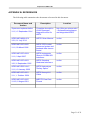
APPENDIX B: REFERENCES
The following table summarizes the documents referenced in this document.
Document Name and
Version
Supercam-Implementation
Description
Location
V1.5, 12 September 2014
Complete description
of the Supercam
integration effort for
APEX.
http://loke.as.arizona.edu/
~ckulesa/binaries/superc
am/integration/APEX/
APEX-MPI-MAN-0011
APECS User Manual
online
APEX SCPI socket
command syntax and
backend data stream
format
online
APEX Instruments
Generic CORBA IDL
Interfaces
online
APEX Standard
Hardware Interfaces
online
APEX Heterodyne
Tertiary Optics
online
APEX Nasmyth A
Cabin
online
MBFITS Raw Data
Format
online
V3.0, 21 July 2014
APEX-MPI-ICD-0005
V1.0, 29 March 2006
APEX-MPI-ICD-0004
V1.9, 3 April 2007
APEX-MPI-ICD-0003
V0.5, 6 September 2002
APEX-MPI-DSD-0012
V1.0, 10 January 2006
APEX-MPI-ICD-0001
V1.1, 1 October 2004
APEX-MPI-ICD-0002
V1.63, 5 August 2011
Page 31 of 32
Supercam at APEX: ICD
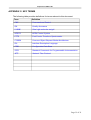
APPENDIX C: KEY TERMS
The following table provides definitions for terms relevant to this document.
Term
Definition
C&C
Command and Control
QA
Quality Assurance
UHMW
Ultra high molecular weight
APECS
APEX Control System
FFTS
Fast Fourier Transform Spectrometer
CORBA
Common Object Request Broker Architecture
IDL
Interface Description Language
CDB
Configuration Data Base
SCPI
Standard Commands for Programmable Instrumentation
NTP
Network Time Protocol
Page 32 of 32