1
MIPS® SEAD™-3 Basic RTL User’s
Manual
Document Number: MD00693
Revision 01.00
March 10, 2010
MIPS Technologies, Inc.
955 East Arques Avenue
Sunnyvale, CA 94085-4521
Copyright © 2009, 2010 MIPS Technologies Inc. All rights reserved.
Copyright © 2009, 2010 MIPS Technologies, Inc. All rights reserved.
Unpublished rights (if any) reserved under the copyright laws of the United States of America and other countries.
This document contains information that is proprietary to MIPS Technologies, Inc. ("MIPS Technologies"). Any copying, reproducing, modifying or use of
this information (in whole or in part) that is not expressly permitted in writing by MIPS Technologies or an authorized third party is strictly prohibited. At a
minimum, this information is protected under unfair competition and copyright laws. Violations thereof may result in criminal penalties and fines.
Any document provided in source format (i.e., in a modifiable form such as in FrameMaker or Microsoft Word format) is subject to use and distribution
restrictions that are independent of and supplemental to any and all confidentiality restrictions. UNDER NO CIRCUMSTANCES MAY A DOCUMENT
PROVIDED IN SOURCE FORMAT BE DISTRIBUTED TO A THIRD PARTY IN SOURCE FORMAT WITHOUT THE EXPRESS WRITTEN
PERMISSION OF MIPS TECHNOLOGIES, INC.
MIPS Technologies reserves the right to change the information contained in this document to improve function, design or otherwise. MIPS Technologies does
not assume any liability arising out of the application or use of this information, or of any error or omission in such information. Any warranties, whether
express, statutory, implied or otherwise, including but not limited to the implied warranties of merchantability or fitness for a particular purpose, are excluded.
Except as expressly provided in any written license agreement from MIPS Technologies or an authorized third party, the furnishing of this document does not
give recipient any license to any intellectual property rights, including any patent rights, that cover the information in this document.
The information contained in this document shall not be exported, reexported, transferred, or released, directly or indirectly, in violation of the law of any
country or international law, regulation, treaty, Executive Order, statute, amendments or supplements thereto. Should a conflict arise regarding the export,
reexport, transfer, or release of the information contained in this document, the laws of the United States of America shall be the governing law.
The information contained in this document constitutes one or more of the following: commercial computer software, commercial computer software
documentation or other commercial items. If the user of this information, or any related documentation of any kind, including related technical data or manuals,
is an agency, department, or other entity of the United States government ("Government"), the use, duplication, reproduction, release, modification, disclosure,
or transfer of this information, or any related documentation of any kind, is restricted in accordance with Federal Acquisition Regulation 12.212 for civilian
agencies and Defense Federal Acquisition Regulation Supplement 227.7202 for military agencies. The use of this information by the Government is further
restricted in accordance with the terms of the license agreement(s) and/or applicable contract terms and conditions covering this information from MIPS
Technologies or an authorized third party.
MIPS, MIPS I, MIPS II, MIPS III, MIPS IV, MIPS V, MIPS-3D, MIPS16, MIPS16e, MIPS32, MIPS64, MIPS-Based, MIPSsim, MIPSpro, MIPS Technologies
logo, MIPS-VERIFIED, MIPS-VERIFIED logo, 4K, 4Kc, 4Km, 4Kp, 4KE, 4KEc, 4KEm, 4KEp, 4KS, 4KSc, 4KSd, M4K, M14K, 5K, 5Kc, 5Kf, 24K, 24Kc,
24Kf, 24KE, 24KEc, 24KEf, 34K, 34Kc, 34Kf, 74K, 74Kc, 74Kf, 1004K, 1004Kc, 1004Kf, R3000, R4000, R5000, ASMACRO, Atlas, "At the core of the
user experience.", BusBridge, Bus Navigator, CLAM, CorExtend, CoreFPGA, CoreLV, EC, FPGA View, FS2, FS2 FIRST SILICON SOLUTIONS logo, FS2
NAVIGATOR, HyperDebug, HyperJTAG, JALGO, Logic Navigator, Malta, MDMX, MED, MGB, microMIPS, OCI, PDtrace, the Pipeline, Pro Series, SEAD,
SEAD-2, SmartMIPS, SOC-it, System Navigator, and YAMON are trademarks or registered trademarks of MIPS Technologies, Inc. in the United States and
other countries.
All other trademarks referred to herein are the property of their respective owners.
Template: nB1.03, Built with tags: 2B
MIPS® SEAD™-3 Basic RTL User’s Manual, Revision 01.00
Copyright © 2009, 2010 MIPS Technologies Inc. All rights reserved.
Table of Contents
Chapter 1: Introduction .......................................................................................................................... 9
1.1: Features ...................................................................................................................................................... 9
1.2: Block Diagram ............................................................................................................................................. 9
Chapter 2: X-Bus Controller ................................................................................................................ 11
2.1: First-level Address Mapping ...................................................................................................................... 11
2.2: DDR2-SDRAM at Start of Memory ............................................................................................................ 12
2.3: X-Bus Controller Internal Architecture ....................................................................................................... 12
Chapter 3: Memory Map and Register Access Rules ........................................................................ 15
3.1: Uncached Access of Registers.................................................................................................................. 16
3.2: Accesses to Illegal/Reserved Addresses .................................................................................................. 16
3.3: Register Macros ........................................................................................................................................ 16
3.4: Alignment................................................................................................................................................... 17
3.5: Reserved Bits ............................................................................................................................................ 17
3.6: SEAD3 CFG Register................................................................................................................................ 17
Chapter 4: Peripheral Bus Controller ................................................................................................. 19
4.1: Peripheral Bus Controller Internal Registers ............................................................................................. 20
4.1.1: Timing Parameters for Other External Peripherals .......................................................................... 21
4.1.2: SRAM Timing Parameters ............................................................................................................... 22
4.1.3: NMI Interrupt Latch Status Register................................................................................................. 22
4.1.4: NMI Interrupt Acknowledge Register ............................................................................................... 23
4.1.5: SW Board Reset Register ................................................................................................................ 23
4.1.6: PIC32 USB Status Register ............................................................................................................. 24
4.1.7: SW Endian Register......................................................................................................................... 24
4.2: External Peripheral Bus Registers............................................................................................................. 25
4.2.1: P-SWITCH ....................................................................................................................................... 25
4.2.2: F-SWITCH........................................................................................................................................ 26
4.2.3: P-LED............................................................................................................................................... 26
4.2.4: F-LED............................................................................................................................................... 27
4.2.5: NEWSC-LIVE................................................................................................................................... 27
4.2.6: NEWSC-REG................................................................................................................................... 28
4.2.7: NEWSC-CTRL ................................................................................................................................. 28
4.2.8: Revision Info .................................................................................................................................... 29
4.2.9: 2-line 16-character Alphanumeric LCD Display ............................................................................... 29
4.2.10: Device Reset Register ................................................................................................................... 30
4.2.11: UARTs............................................................................................................................................ 30
Chapter 5: DDR2 SDRAM Controller ................................................................................................... 31
5.1: CPU Accessible Registers......................................................................................................................... 32
5.1.1: DDR2 SDRAM Presence Detected Configuration ........................................................................... 32
5.1.2: DDR2 SDRAM Presence Detected Read Address Register............................................................ 32
5.1.3: DDR2 SDRAM Presence Detected Transfer Register ..................................................................... 33
Chapter 6: USB-HS 2.0 Controller ....................................................................................................... 35
MIPS® SEAD™-3 Basic RTL User’s Manual, Revision 01.00
Copyright © 2009, 2010 MIPS Technologies Inc. All rights reserved.
3
6.1: CPU-accessible USB Registers ................................................................................................................ 35
Chapter 7: Interrupt Controller ............................................................................................................ 37
7.1: MIPS Global Interrupt Controller (GIC) Interface....................................................................................... 37
Appendix A: References ...................................................................................................................... 39
Appendix B: Revision History ............................................................................................................. 41
4
MIPS® SEAD™-3 Basic RTL User’s Manual, Revision 01.00
Copyright © 2009, 2010 MIPS Technologies Inc. All rights reserved.
List of Figures
Figure 1.1: SEAD-3 Basic RTL Block Diagram ....................................................................................................... 10
Figure 2.1: EC/AHB/OCP-to-X-bus Controller Internal Datapath............................................................................ 13
Figure 4.1: Default Access Timing for Peripheral Bus Devices............................................................................... 20
Figure 5.1: DDR2 SDRAM Controller Block Diagram ............................................................................................. 31
Figure 6.1: USB-HS 2.0 Controller Block Diagram ................................................................................................. 35
Figure 7.1: Interrupt Interface to GIC ..................................................................................................................... 38
MIPS® SEAD™-3 Basic RTL User’s Manual, Revision 01.00
Copyright © 2009, 2010 MIPS Technologies Inc. All rights reserved.
5
6
MIPS® SEAD™-3 Basic RTL User’s Manual, Revision 01.00
Copyright © 2009, 2010 MIPS Technologies Inc. All rights reserved.
List of Tables
Table 2.1: SEAD-3 X-bus Controller First-level Address Map ................................................................................ 11
Table 3.1: SEAD-3 Physical Memory Map.............................................................................................................. 15
Table 3.2: SEAD3 CFG register.............................................................................................................................. 17
Table 4.1: PI_TIMOTHER Register......................................................................................................................... 21
Table 4.2: PI_TIMSRAM Register........................................................................................................................... 22
Table 4.3: PI_NMISTATUS Register....................................................................................................................... 23
Table 4.4: PI_NMIACK register............................................................................................................................... 23
Table 4.5: PI_SWRESET register ........................................................................................................................... 23
Table 4.6: PI_PIC32_USB_STATUS Register........................................................................................................ 24
Table 4.7: PI_SOFTENDIAN Register .................................................................................................................... 24
Table 4.8: PSWITCH Register ................................................................................................................................ 25
Table 4.9: FSWITCH Register ................................................................................................................................ 26
Table 4.10: PLED Register ..................................................................................................................................... 26
Table 4.11: FLED Register ..................................................................................................................................... 27
Table 4.12: NEWSC-LIVE Register ........................................................................................................................ 27
Table 4.13: NEWSC-REG Register ........................................................................................................................ 28
Table 4.14: NEWSC-CTRL Register....................................................................................................................... 28
Table 4.15: REVISION Register ............................................................................................................................. 29
Table 4.16: ASCII Display Registers....................................................................................................................... 29
Table 4.17: PI_DEVRST register ............................................................................................................................ 30
Table 4.18: UART Registers ................................................................................................................................... 30
Table 5.1: DDR2 SDRAM Controller Module Registers, BASE = 0x1B00.0000..................................................... 32
Table 5.2: SD_SPDCNF Register ........................................................................................................................... 32
Table 5.3: SD_SPDADR register ............................................................................................................................ 32
Table 5.4: SD_SPDDAT Register ........................................................................................................................... 33
Table 6.1: USB Slave Interface Register Sets Base at 0x1b20.0000 ..................................................................... 36
Table 7.1: Direct Mapped Interrupt Scheme ........................................................................................................... 37
Table 7-1: GIC Global Interrupt Source Pin Mapping ............................................................................................. 38
MIPS® SEAD™-3 Basic RTL User’s Manual, Revision 01.00
Copyright © 2009, 2010 MIPS Technologies Inc. All rights reserved.
7
8
MIPS® SEAD™-3 Basic RTL User’s Manual, Revision 01.00
Copyright © 2009, 2010 MIPS Technologies Inc. All rights reserved.
Chapter 1
Introduction
This document describes the capabilities of the SEAD™-3 Basic RTL source code included in the MIPS SEAD-3
Basic Package, as seen from the programmer’s point of view. This source code is a sample design which interfaces to
the CPU core and implements all necessary control logic for the external resources including SDRAM.
The SEAD-3 Basic RTL is intended for demonstration purposes and as inspiration for the user. It enables the user to
bring-up the board as a fully functional CPU system, and to to exercise the board’s functionality, while developing
their own RTL.
Note that future versions of the SEAD-3 Basic RTL may be totally different from the current version, and MIPS does
not support any user-modified RTL. The SEAD-3 Basic RTL is therefore delivered “as is”.
This document assumes that the reader has read the the SEAD™-3 Basic RTL Reference Manual [1], the SEAD™-3
Board User’s Manual [2], and SEAD-3™ Board Getting Started [3].
1.1 Features
The SEAD-3 Basic RTL code implements the following features:
•
Interface to the CPU core bus (EC /AHB/OCP interface) for 32-bit CPUs
•
Interface to Xilinx DDR2 -SDRAM controller
•
Peripheral bus controller
•
Interface to Synopsys USB-HS 2.0 OTG controller
•
Interface to MIPS Global Interrupt Controller
All the RTL code is written in Verilog.
The Basic RTL and YAMON ROM monitor support dual endianness without any need to recompile. The RTL can be
compiled for a 32-bit CPU.
The SEAD-3 Basic RTL has two clock domains. The DDR2-SDRAM controller is in domain 1, and all other modules
are in domain 2 (the DDR2-SDRAM controller domain is synthesized to run upto 266 MHz1, and the maximum frequency of domain 2 is 83 MHz).
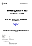
1.2 Block Diagram
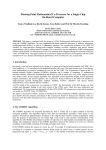
A block diagram of the Basic RTL is shown in Figure 1.1.
1 The
SEAD-3 Basic RTL requires that the domain 1 supplied frequency is half the domain frequency MHz.
MIPS® SEAD™-3 Basic RTL User’s Manual, Revision 01.00
Copyright © 2009, 2010 MIPS Technologies Inc. All rights reserved.
9
Introduction
Figure 1.1 SEAD-3 Basic RTL Block Diagram
Board Interrupts
MIPS
Global Interrupt Controller
MIPS
M14K/c
CPU
EC / AHB/OCP
EC/AHB/OCP-to-X-Bus Controller
SI_Int
O C P Slave
Peripheral
Bus
X-bus #1
Controller
X-bus #3
X-bus #2
X-bus #0
USB
BVCI Master/Slave
User Interface
Xilinx
DDR2-SDRAM Controller
Optional
Peripheral
Bus
DDR2 Bus
Synopsys
USB-HS 2.0 Controller
UPLI Bus
All the blocks shown in the figure are described in detail in later chapters of this document.
The CPU has access to four slaves that are mapped to the X-bus: the Peripheral bus controller, DDR2-SDRAM controller, Global Interrupt Controller, and US-HS 2.0 OTG controller. The X-bus is a 32-bit fully synchronous, single-master-multi-target, non-tristate bus (see [2] for details). The DDR2-SDRAM controller can be accessed from the
USB or CPU—USB has the higher priority, though if the CPU is in the middle of a burst access, USB must wait until
the burst trasaction is complete.
In the Basic RTL, all blocks other than Peripheral bus controller and the EC/AHB/OCP-to-X-bus controller are
optional and must be selected as build-time options.
To select an internal MIPS CPU, users must have access to the RTL source for the MIPS32 M14K CPU. The Basic
RTL will select a external CPU module when present on the CoreBus connector.
The Basic RTL provides an interface to the Xilinx DDR2-SDRAM controller and Synopsys USB-HS 2.0 OTG controller. The user must have access to the RTL for the respective option if they are selected in the build.
Interrupts on the board are directly mapped to processor interrupts when the Global Interrupt Controller option is not
selected. See Chapter 7, “Interrupt Controller” on page 37.
The Basic RTL is a fully synchronous design; all flops are clocked on the positive edge of the global clock. There are
no latches, no tri-states, no asynchronous resets, no gated clocks, or other design practices that make implementing an
ASIC difficult.
10
MIPS® SEAD™-3 Basic RTL User’s Manual, Revision 01.00
Copyright © 2009, 2010 MIPS Technologies Inc. All rights reserved.
Chapter 2
X-Bus Controller
The X-bus controller supports either an EC, AHB, or OCP front-end interface and four X-bus master ports, as illustrated in Figure 1.1. Although four separate busses are shown in the Figure, the address bus and write data bus originating from the X-bus controller are actually shared between the X-bus targets. However, in order to avoid tri-state
busses, each of the four targets has its own read data bus. As a build time option, the user can select either an EC- ,
AHB-, or OCP-based bus on the CPU bus interface.
2.1 First-level Address Mapping
The X-bus controller contains a fixed (hardcoded) first-level address mapping, which maps the physical address
space from the CPU to the X-bus ports. An X-bus may be used for data transfers (typically memories) and/or register
accesses. For X-busses with both types of functions, the X-bus controller decodes two segments. The address mapping is shown in Table 2.1.
Table 2.1 SEAD-3 X-bus Controller First-level Address Map
Physical Address Range
Type
Function
0x0.0000.0000 - 0x0.0FFF.FFFF
Data
X-bus #0 (DDR2-SDRAM controller)
0x0.1000.0000 - 0x0.1AFF.FFFF
Data
X-bus #0 (DDR2-SDRAM controller)
0x0.1B00.0000 - 0x0.1B0F.FFFF
Registers
X-bus #0 (DDR2-SDRAM controller)
0x0.1B10.0000 - 0x0.1B1F.FFFF
Registers
X-bus #1 (GIC)
0x0.1B20.0000 - 0x0.1B2F.FFFF
Registers
X-bus #2 (USB-HS 2.0 OTG)
0x0.1B30.0000 - 0x0.1BFF.FFFF
-
0x0.1C00.0000 - 0x0.1EFF.FFFF
Data
X-bus #3 (Peripheral bus controller)
0x0.1F00.0000 - 0x0.1F00.01FF
Registers
X-bus #3 (Peripheral bus controller)
0x0.1F00.0200 - 0x0.1FFF.FFFF
Data
X-bus #3 (Peripheral bus controller)
Reserved
The X-bus controller only decodes address bits 28:20 (in the case of target 3 register decode, bits 28:9) in order to
map the accesses to the correct target ports. Because the EC interface address bits 35:29 or AHB or OCP interface
address bits 31:29 are not included in the address decoding, the address segment 0x0.0000.0000-0x0.1FFF.FFFF will
be “mirrored” to 0x0.2000.0000-0x0.3FFFF.FFFF and 0x0.4000.0000-0x0.5FFF.FFFF, etc.
In CPUs with a fixed mapping MMU, the virtual base address of the user segment (useg/kuseg) 0x0.0000.0000 maps
to physical base address 0x0.4000.0000, which will be mirrored to address 0x0.0000.0000 in the SEAD-3 Basic RTL.
The kseg0 and kseg1 kernel segments both map to the physical address segment 0x0.0000.0000-0x0.1FFF.FFFF, so
care should be taken in order to avoid mirroring user code and data onto the same physical addresses as the kernel
code and data. User code should therefore not be linked to virtual base address 0x0.0000.0000, but should be linked
to some higher address, which is certain not to be mirrored onto kernel code and data.
MIPS® SEAD™-3 Basic RTL User’s Manual, Revision 01.00
Copyright © 2009, 2010 MIPS Technologies Inc. All rights reserved.
11
X-Bus Controller
2.2 DDR2-SDRAM at Start of Memory
Because all exception vectors are located at the bottom of memory following boot, some sort of memory device must
be mapped to the beginning of the physical address space. In the SEAD-3 Basic RTL, memory-device mapping is
selected by the sram_map_zero switch on the SEAD-3 board, Switch position sram_map_zero ON will map SRAM
to physical address 0x0; DDR2-SDRAM is mapped to the beginning of memory(address 0x0) when this switch position is OFF. If the DDR2-SDRAM option is not selected during build, then SRAM will be mapped to zero, regardless
of the switch position.
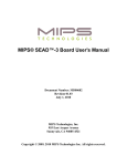
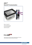
2.3 X-Bus Controller Internal Architecture
The X-bus controller separates read and write requests in such a way that it permits simultaneous outstanding reads
on one port and active write requests on another port. The “data path” of the X-bus controller is illustrated in the
Figure 2.1. Address and write data originating from the EC/AHB/OCP interface is either directly output to the
addressed X-bus target (through an optional set of output flops, to improve timing), or it is saved in registers until it
can be accepted by the X-bus target. Read data returned from an X-bus target is simply passed directly to the
EC/AHB/OCP interface (however we need a mux, because each X-bus target has its own read data bus). Timing is
relaxed by adding a level of registers on the read data path, but no changes are needed in the control/protocol logic.
The control logic is quite complex (see [2]).
12
MIPS® SEAD™-3 Basic RTL User’s Manual, Revision 01.00
Copyright © 2009, 2010 MIPS Technologies Inc. All rights reserved.
2.3 X-Bus Controller Internal Architecture
Figure 2.1 EC/AHB/OCP-to-X-bus Controller Internal Datapath
EC/AHB/OCP-to-X-bus controller
optional output flops
X-bus shared address bus
reg’s
reg’s
EC/AHB/OCP write data bus
mux
X-bus shared write data bus
reg’s
reg’s
mux
EC/AHB/OCP read data bus
MIPS® SEAD™-3 Basic RTL User’s Manual, Revision 01.00
Copyright © 2009, 2010 MIPS Technologies Inc. All rights reserved.
Individual read data busses
for each X-bus target
EC/AHB/OCP Interface
mux
EC/AHB/OCP address bus
13
X-Bus Controller
14
MIPS® SEAD™-3 Basic RTL User’s Manual, Revision 01.00
Copyright © 2009, 2010 MIPS Technologies Inc. All rights reserved.
Chapter 3
Memory Map and Register Access Rules
The default physical memory map as seen from the CPU core is shown in Table 3.1 below. This map can be modified
by users; no mapping restrictions are imposed by hardware.
Table 3.1 SEAD-3 Physical Memory Map
Base address
Size
Function
0x0000.0000
32 - 256 Mbytes
0x1000.0000
176 Mbytes
0x1B00.0000
1 Mbyte
DDR2-SDRAM controller registers
0x1B10.0000
1 Mbyte
SEAD-3 CFG and GIC registers
0x1B20.0000
1 Mbyte
USB-HS 2.0 OTG registers
0x1B30.0000
13 Mbytes
Reserved
0x1C00.0000
32 Mbyte
Flash (memory)
0x1E00.0000
4 Mbytes
SRAM (memory)
0x1E40.0000
4 Mbytes
SRAM(memory), if available
0x1E80.0000
8 Mbytes
Reserved
0x1F00.0000
512 bytes
Peripheral bus controller internal registers
0x1F00.0200
56 bytes
P-SWITCH
DDR2-SDRAM SODIMM(memory)
DDR2-SDRAM SODIMM(memory), accessible only
when 512MB single rank SODIMM is used
F-SWITCH
P-LED
F-LED
NEWSC-LIVE
NEWSC-REG
NEWSC-CTRL
Reserved
0x1F00.0240
448 bytes
Reserved
0x1F00.0400
16 bytes
LCD Data register
0x1F00.0410
8 bytes
CPLD LCD Status register
0x1F00.0418
8 bytes
CPLD LCD Data register
0x1F00.0480
8 bytes
Device Reset register
0x1F00.0500
256 bytes
Reserved
0x1F00.0600
256 bytes
PIC32 device
0x1F00.0700
256 bytes
Reserved
0x1F00.0800
256 bytes
UART #0
MIPS® SEAD™-3 Basic RTL User’s Manual, Revision 01.00
Copyright © 2009, 2010 MIPS Technologies Inc. All rights reserved.
15
Memory Map and Register Access Rules
Table 3.1 SEAD-3 Physical Memory Map (Continued)
Base address
Size
Function
0x1F00.0900
256 bytes
UART #1
0x1F00.0A00
62 Kbytes
Reserved
0x1F01.0000
64 Kbytes
ETHERNET device
0x1F02.0000
3.896 Mbytes
0x1F40.0000
4 Mbytes
USER Board
0x1F80.0000
2 Mbytes
Reserved, FPGA-ROM space
0x1FA0.0000
6 Mbytes
SW-EPROM (Boot PROM memory),
REVISION register at address 0x1FC0.0010
Reserved
Note: To ensure future compatibility, address 1FC0.0010 is “special”, in the sense that it does NOT decode to an
address in the SW-EPROM, but rather to register address REVISION. The YAMON ROM monitor uses the REVISION register to identify the hardware platform and configure its drivers accordingly.
3.1 Uncached Access of Registers
To avoid cache coherency problems, all registers internal to Basic RTL modules and in the peripheral bus devices
must be accessed in uncached mode. Such problems can arise, for example, when a dynamically changing status register is polled.
If the program runs in kernel mode, these registers can be accessed via kseg1 mapping, since kseg1 is non-cacheable.
In the rest of this document, only 32-bit physical register addresses are provided; a 32-bit physical address can be
converted to a 32-bit kseg1 address by OR’ing it with 0xA000.0000. For example, if the peripheral bus controller register PI_TIMSRAM has physical address 0x1F00.0010, the virtual kseg1 address, which kernel mode programs
should use, is (0x1F00.0010 | 0xA000.0000) = 0xBF00.0010.
3.2 Accesses to Illegal/Reserved Addresses
If the CPU attempts to access any of the above reserved areas, the X-bus controller will map those accesses to X-bus
target #2 as type “Data”. This targets normal function is “Register” only, so it is easy for this target to detect these
illegal accesses (and thus make a simpler X-bus controller implementation). The X-bus targets will generally signal
“read bus error” to the master, in case of illegal read accesses. The master will forward any read bus error to the CPU
(via the EC/AHB/OCP interface), which will take an exception. In order to make sure that any illegal write access is
noticed, all the X-bus targets are required to issue a “write access error pulse” to NMI logic in the peripheral bus controller when they detect an illegal write access. The NMI logic forces the CPU to take an NMI exception when a
“write access error pulse” from any of the targets is detected (see section Chapter 3, “Memory Map and Register
Access Rules” on page 15).
3.3 Register Macros
Though explicit addresses are listed in the following sections, it is recommended to use the macros in the “sead.h”
header file, which is included with the YAMON source code. Note that all register defines in this header file are prefixed with “SEAD_”, to be able to easily distinguish these hardware-specific defines from other defines.
16
MIPS® SEAD™-3 Basic RTL User’s Manual, Revision 01.00
Copyright © 2009, 2010 MIPS Technologies Inc. All rights reserved.
3.4 Alignment
3.4 Alignment
All registers are addressed as 32-bit words on 64-bit word boundaries. This convention prevents any problems due to
Endianness (see the X-bus specification in [2] for details).
3.5 Reserved Bits
Register bits marked as “reserved” are reserved for future use. To ensure software compatibility with future versions
of the SEAD-3 Basic RTL, software should always write 0 to reserved bits and ignore reserved bits on reads.
Reserved bits will return 0 on reads; however, this may change in future versions of the SEAD-3 Basic RTL.
3.6 SEAD3 CFG Register
Name:
Address:
Access:
SEAD3_CFG
0x1B10.0110
RO
The SEAD3_CFG register describes BRTL and Board Configuration. BRTL configuration is set in the rtl build process. SRAM_MAP_ZERO and FPGA_OPT are switches on the SEAD3 board.
Table 3.2 SEAD3 CFG register
Fields
Name
Bits
Description
0
31:5
Must be written as zero; return zero on read.
RO
USB_PRESENT
4
0 = Not present, no usb support
1 = Present, USB-HS 2.0 Controller Interface
RO
DDR2_PRESENT
3
0 = Not present, no dram support and sram will be mapped to
address 0x0
1 = Present, DRAM interface is DDR2
RO
SRAM_SIZE
2
0 = sram size is 4MB, FPGA_OPT switch in OFF position
1 = sram size is 8MB, FPGA_OPT switch in ON position
RO
GIC_PRESENT
1
0 = Not present, Interrupts are directly mapped
1 = Present, Interrupt Controller is GIC
RO
ADDRESS_0X0_
DEVICE
0
0 = dram mapped to address 0x0, SRAM_MAP_ZERO switch in
OFF position
1 = sram mapped to address 0x0, SRAM_MAP_ZERO switch in
ON position
RO
MIPS® SEAD™-3 Basic RTL User’s Manual, Revision 01.00
Copyright © 2009, 2010 MIPS Technologies Inc. All rights reserved.
Access
17
Memory Map and Register Access Rules
18
MIPS® SEAD™-3 Basic RTL User’s Manual, Revision 01.00
Copyright © 2009, 2010 MIPS Technologies Inc. All rights reserved.
Chapter 4
Peripheral Bus Controller
The Peripheral bus controller connects the CPU to all SEAD-3 peripherals on the external peripheral bus. The
peripheral bus is a simple asynchronous, no-handshake, non-burst bus.
The following peripherals are connected to the SEAD-3 peripheral bus:
•
6 MByte SW-PROM (Boot EPROM)
•
32 MByte Flash
•
4 MByte SRAM
•
16 software readable DIP switches (P-SWITCH, F-SWITCH)
•
16-bar software controlled LEDs (P-LED, F-LEDs)
•
2-line 16-character alphanumeric LCD display
•
PIC32 device that controls I2C, SPI, ADC, GPIO interface
•
Ethernet controller
•
CPLD board controller
•
2 UARTs (TL16C550)
•
Board part of REVISION register
Note that the peripheral bus on the SEAD-3 board can be disconnected from the FPGA by means of configurable
CBT-switches. This is described in [2].
The peripheral bus access timing can be programmed via two internal registers in the Peripheral bus controller. The
Peripheral bus controller also handles the NMI interrupt debouncing, latching, and the board reset. These registers are
all described in section Section 4.1 “Peripheral Bus Controller Internal Registers” below.
Each of the X-bus targets in the Basic RTL outputs a “write access error pulse” signal to logic residing in the Peripheral controller module, which ORs all these signals onto the SI_NMI signal. This ensures that the CPU takes an NMI
exception whenever an illegal write access is detected by the Basic RTL. Illegal read accesses are signalled on the
EC/AHB/OCP interface using the read bus error signal. See also Section 3.2 “Accesses to Illegal/Reserved
Addresses”.
The interrupt lines from the UARTs are also part of the peripheral bus; these are connected to the interrupt controller
source, and are simply passed through the SEAD-3 Basic RTL directly to the interrupt lines on the CPU. Interrupt
mapping is described in Chapter 7, “Interrupt Controller” on page 37.
MIPS® SEAD™-3 Basic RTL User’s Manual, Revision 01.00
Copyright © 2009, 2010 MIPS Technologies Inc. All rights reserved.
19
Peripheral Bus Controller
All the registers and programming details for the external devices attached to the peripheral bus are listed in section
Section 4.2 “External Peripheral Bus Registers” below.
4.1 Peripheral Bus Controller Internal Registers
The peripheral bus is a simple asynchronous, non-burst bus, which has the following data and control signals1:
•
PI_A[24:0]- address bus
•
PI_D[31:0]- bidirectional data bus
•
PI_SEL[4:0]- device select (mapped from address)
•
PI_CS_N- common chip select
•
PI_RD_N- read strobe
•
PI_BE_N[3:0]- byte enable strobes
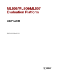
Figure 4.1shows the basic timing of read and write accesses (back-to-back read followed by write) for all devices on
the peripheral bus except SRAM.
Figure 4.1 Default Access Timing for Peripheral Bus Devices
gclk
gclk cycle
0
1
2
3
4
5
6
7
8
0
1
2
3
4
5
6
PI_A[24:0]
read address valid
write address valid
PI_SEL[4:0]
read select valid
write select valid
7
8
write data valid
PI_D[31:0]
PI_CS_N
PI_RD_N
PI_BE_N[3:0]
1111
asserted
1111
The Peripheral bus controller contains two bus-timing registers (with identical layout); the first register controls the
bus timing for SRAM accesses, and the other register is a common bus-timing register for all the other devices on the
peripheral bus. It is therefore possible to use a fast access timing for the SRAM, while having a slow timing for the
remaining devices.
The “gclk cycle” counter in Figure 4.1 illustrates how an internal access counter is used to control when to assert /
de-assert the various peripheral bus control signals. This counter equals the “ADH” field of the timing register in the
1 The
interrupt lines from the UARTs, PI_UART<n>_INT_N, are also part of the peripheral bus, but they are not related to the
peripheral bus accesses. In the Basic RTL, they are wired directly to the CPU interrupt lines 0 and 1.
20
MIPS® SEAD™-3 Basic RTL User’s Manual, Revision 01.00
Copyright © 2009, 2010 MIPS Technologies Inc. All rights reserved.
4.1 Peripheral Bus Controller Internal Registers
last clock cycle of a peripheral bus access (see Section 4.1.2 “SRAM Timing Parameters” and Section
4.1.1 “Timing Parameters for Other External Peripherals”).
The default timing for accessing all peripherals except the SRAM is as follows:
For both read and write accesses, PI_A[] and PI_SEL[] are valid one clock cycle before PI_CS_N is asserted,
and stay valid until one clock cycle after PI_CS_N is deasserted. For read accesses, the read data is sampled
when PI_RD_N is deasserted (at the end of cycle 6 in Figure 4.1 above), so the read data does not have to be
valid until the last asserted cycle of PI_RD_N. For write accesses, the write data is valid when PI_CS_N is
asserted, and stays valid until one clock cycle after PI_CS_N is deasserted. The write strobes, PI_WE_N[], are
deasserted one clock cycle after PI_CS_N, and are deasserted one clock cycle before PI_CS_N.
This behavior can be changed by modifying the contents of the PI_TIMOTHER register. But note that it is possible to program access timing setups which will not work in practice, so care should be taken when the peripheral bus timing is changed from the default.
4.1.1 Timing Parameters for Other External Peripherals
Name:
Address:
Access:
Reset Value:
PI_TIMOTHER
0x1F00.0020
R/W
0x61469354
The PI_TIMOTHER register controls the timing of accesses to all external peripherals on the peripheral bus, except
the SRAM (which has its own timing register, PI_TIMSRAM). The slowest device on the peripheral bus thus dictates
the timing of all the remaining devices (except for the SRAM). The default value assumes that the system is not running faster than 83 MHz. All field values are interpreted as a number of clock cycles counting from the access start
time, as illustrated for the PI_TIMOTHER default values in Figure 4.1.
Table 4.1 PI_TIMOTHER Register
Bits
Field name
Function
Initial Value
31:26
ADH
Address and write data hold time
Legal values: CS2+1 to 63 (inclusive)
0x18
25:20
WE2
Write enable deassertion time
Legal values: WE1+1 to ADH-1 (inclusive)
0x14
19:17
WE1
Write enable assertion time
Legal values: CS1+1 to WE2-1 (inclusive)
0x3
16:11
RD2
Read strobe deassertion time
Legal values: RD1+1 to ADH-1 (inclusive)
0x12
10:8
RD1
Read strobe assertion time
Legal values: CS1+1 to RD2-1 (inclusive)
0x3
7:2
CS2
Chip select deassertion time
Legal values: max(RD2,WE2)+1 to ADH-1
(inclusive)
0x15
1:0
CS1
Chip select assertion time
Legal values: 0 to min(RD1,WE1)-1 (inclusive)
0x0
MIPS® SEAD™-3 Basic RTL User’s Manual, Revision 01.00
Copyright © 2009, 2010 MIPS Technologies Inc. All rights reserved.
21
Peripheral Bus Controller
4.1.2 SRAM Timing Parameters
Name:
Address:
Access:
Reset Value:
PI_TIMSRAM
0x1F00.0010
R/W
0x30703824
The PI_TIMSRAM register controls the timing of accesses to the SRAM. All field values are interpreted as a number
of clock cycles counting from the access start time. Check your oscillator frequency and the SRAM data sheet before
changing values in the PI_TIMSRAM register.
Table 4.2 PI_TIMSRAM Register
Bits
Field name
Function
Initial Value
31:26
ADH
Address and write data hold time
Legal values: CS2+1 to 63 (inclusive)
0xC
25:20
WE2
Write enable deassertion time
Legal values: WE1+1 to ADH-1 (inclusive)
0x7
19:17
WE1
Write enable assertion time
Legal values: CS1 to WE2-1 (inclusive)
0x0
16:11
RD2
Read strobe deassertion time
Legal values: RD1+1 to ADH-1 (inclusive)
0x7
10:8
RD1
Read strobe assertion time
Legal values: CS1 to RD2-1 (inclusive)
0x0
7:2
CS2
Chip select deassertion time
Legal values: max(RD2,WE2) to ADH-1 (inclusive)
0x9
1:0
CS1
Chip select assertion time
Legal values: 0 to min(RD1,WE1) (inclusive)
0x0
4.1.3 NMI Interrupt Latch Status Register
Name:
Address:
Access:
Reset Value:
PI_NMISTATUS
0x1F00.0040
RO
0x00000000
The Peripheral bus controller contains logic to generate an NMI-pulse if either of two cases occurs:
•
the user presses the “ON/OFF” push button
•
a write access to an illegal address is detected
In either case, the FLAG field of the PI_NMISTATUS register is set when an NMI-exception is generated. If the
NMI-exception is generated due to an illegal write access, the WERR bit will also be set.
If an NMI-pulse is signalled to the CPU, the CPU will restart execution from the reset handler. The CPU is then able
to detect that it has restarted due to an NMI interrupt (as opposed to a cold reset) by noting that the PI_NMISTATUS
FLAG bit is set. The CPU can also check the WERR bit to see whether the NMI-exception was generated by an illegal write access or by the user pressing the ON/OFF push button.
22
MIPS® SEAD™-3 Basic RTL User’s Manual, Revision 01.00
Copyright © 2009, 2010 MIPS Technologies Inc. All rights reserved.
4.1 Peripheral Bus Controller Internal Registers
The CPU can clear both PI_NMISTATUS bits by writing a 1 to register PI_NMIACK (see section Section
4.1.4 “NMI Interrupt Acknowledge Register”). Pressing the ON/OFF button will only generate an NMI-interrupt if
PI_NMISTATUS is cleared.
If the ON/OFF button is kept pressed for more than two seconds, the SEAD-3 board will power off. This is controlled
by a on-board timer and does not depend on the system frequency nor the Basic RTL.
Table 4.3 PI_NMISTATUS Register
Bits
31:2
Field name
Initial Value1
Function
Reserved
N/A
1
WERR
Write access error
0
FLAG
Latched NMI status
0x0 - no write access error
0x1 - write access error
0x0 - after cold reset
0x1 - after NMI reset
1. In this case, “Initial value” is the value the CPU sees after any “reset” (including NMI exceptions)
4.1.4 NMI Interrupt Acknowledge Register
Name:
Address:
Access:
Reset Value:
PI_NMIACK
0x1F00.0048
WO
N/A
The CPU can clear the two PI_NMISTATUS bits by writing a 1 to register PI_NMIACK (see also section Section
4.1.3 “NMI Interrupt Latch Status Register”).
Table 4.4 PI_NMIACK register
Bits
31:1
0
Field name
Function
Initial Value
Reserved
N/A
ACK
Acknowledge NMI, and clear PI_NMISTATUS
N/A
4.1.5 SW Board Reset Register
Name:
Address:
Access:
Reset Value:
PI_SWRESET
0x1F00.0050
WO
N/A
Table 4.5 PI_SWRESET register
Bits
Field name
31:8
Reserved
7:0
SWRST
Function
Initial Value
N/A
Writing 0x4D to this register field will generate
a board reset.
MIPS® SEAD™-3 Basic RTL User’s Manual, Revision 01.00
Copyright © 2009, 2010 MIPS Technologies Inc. All rights reserved.
0x0
23
Peripheral Bus Controller
4.1.6 PIC32 USB Status Register
Name:
Address:
Access:
Reset Value:
PI_PIC32_USB_STATUS
0x1F00.0060
RO
N/A
Table 4.6 PI_PIC32_USB_STATUS Register
Bits
31
Field name
USB
Function
Initial Value
USB device interrupt. This field is set to 1’b1
when usb device need to interrupt cpu
0x0
30:4
Reserved
N/A
3
INTID2
PIC32 GPIO Port B interrupt pin
0x0
2
INTID1
PIC32 GPIO Port A interrupt pin
0x0
2
INTID0
PIC32 SPI interrupt pin
0x0
0
IORDY
This field indicates that the pending PIC32 operation has been completed and a status byte is
available in the PIC32 interface read buffer at
address 0.
0x1
4.1.7 SW Endian Register
Name:
Address:
Access:
Reset Value:
PI_SOFTENDIAN
0x1F00.0070
R/W, RO
N/A
Table 4.7 PI_SOFTENDIAN Register
Bits
Function
Initial Value
31
SOFTCONTROL Software control of Endianness and EIC Mode
is supported.
RO
0x1
30
CFGPRESENT
0x1
29:3
2
24
Field name
SEAD-3 CFG register is preset at 0x1b10.0110.
RO
Reserved
EICPresent
N/A
This field is set to zero during power on reset. A
value of 1 will set up CPU in EIC mode. After
power on this bit can be updated only writing to
this register.
RW
0x0
MIPS® SEAD™-3 Basic RTL User’s Manual, Revision 01.00
Copyright © 2009, 2010 MIPS Technologies Inc. All rights reserved.
4.2 External Peripheral Bus Registers
Table 4.7 PI_SOFTENDIAN Register (Continued)
Bits
Field name
Function
Initial Value
1
DONE
This field is set on write to bit0 or bit2, cleared
on write to PI_SWRESET register.
RO.
0x0
0
ENDIAN
This field indicates board switch position
sw_bigend during power on reset, After power
on this bit can be updated only writing to this
register.
RW
N/A
4.2 External Peripheral Bus Registers
The following sections describe the programming of the devices attached to the peripheral bus.
4.2.1 P-SWITCH
Name:
Address:
Access:
Reset Value:
PSWITCH
0x1F00.0200
RO
N/A
This register allows software to monitor the state of the 8 bit P-SWITCH (S3) on the peripheral bus.
Table 4.8 PSWITCH Register
Bits
Field name
31:8
Reserved
7:0
VAL
Function
Initial Value
N/A
8 P-SWITCH bits (physical switches are numbered 8 to 1).
0: OFF/Open
1: ON/Closed
MIPS® SEAD™-3 Basic RTL User’s Manual, Revision 01.00
Copyright © 2009, 2010 MIPS Technologies Inc. All rights reserved.
N/A
25
Peripheral Bus Controller
4.2.2 F-SWITCH
Name:
Address:
Access:
Reset Value:
FSWITCH
0x1F00.0208
RO
N/A
This register allows software to monitor the state of the 8 bit F-SWITCH (S4) on the peripheral bus.
Table 4.9 FSWITCH Register
Bits
Field name
31:8
Reserved
7:0
VAL
Function
Initial Value
N/A
N/A
8 F-SWITCH bits (physical switches are numbered 8 to 1).
0: OFF/Open
1: ON/Closed
4.2.3 P-LED
Name:
Address:
Access:
Reset Value:
PLED
0x1F00.0210
R/W
0x00000000
The PLED register allows software to program the state of the 8 P-LED bits on the peripheral bus.
Table 4.10 PLED Register
Bits
26
Field name
31:8
Reserved
7:0
VAL
Function
Initial Value
N/A
8 bits corresponding to the 8 P-LED bits.
0: Off
1: On
0x0
(all P-LED bits off)
MIPS® SEAD™-3 Basic RTL User’s Manual, Revision 01.00
Copyright © 2009, 2010 MIPS Technologies Inc. All rights reserved.
4.2 External Peripheral Bus Registers
4.2.4 F-LED
Name:
Address:
Access:
Reset Value:
FLED
0x1F00.0218
R/W
0x00000000
The FLED register allows software to program the state of the 8 F-LED bits on the peripheral bus.
Table 4.11 FLED Register
Bits
Field name
31:8
Reserved
7:0
VAL
Function
Initial Value
N/A
8 bits corresponding to the 8 F-LED bits.
0: Off
1: On
0x0
(all P-LED bits off)
4.2.5 NEWSC-LIVE
Name:
Address:
Access:
Reset Value:
NEWSC-LIVE
0x1F00.0220
RO
N/A
The NEWSC-LIVE register allows software to read the present state of NEWSC switch. This is an 8-bit wide register.
Table 4.12 NEWSC-LIVE Register
Bits
7:5
Field name
Function
Initial Value
Reserved
N/A
4
sw_cpld_n
Switch position North
N/A
3
sw_cpld_e
Switch position East
N/A
2
sw_cpld_w
Switch position West
N/A
1
sw_cpld_s
Switch position South
N/A
0
sw_cpld_c
Switch position Center
N/A
MIPS® SEAD™-3 Basic RTL User’s Manual, Revision 01.00
Copyright © 2009, 2010 MIPS Technologies Inc. All rights reserved.
27
Peripheral Bus Controller
4.2.6 NEWSC-REG
Name:
Address:
Access:
Reset Value:
NEWSC-REG
0x1F00.0228
RO
N/A
The NEWSC-REG register allows software to read the state of NEWSC switch after debounce. This is an 8-bit wide
register.
Table 4.13 NEWSC-REG Register
Bits
7:5
Field name
Function
Initial Value
Reserved
N/A
4
sw_cpld_n
Switch position North after debounce
N/A
3
sw_cpld_e
Switch position East after debounce
N/A
2
sw_cpld_w
Switch position West after debounce
N/A
1
sw_cpld_s
Switch position South after debounce
N/A
0
sw_cpld_c
Switch position Center after debounce
N/A
4.2.7 NEWSC-CTRL
Name:
Address:
Access:
Reset Value:
NEWSC-CTRL
0x1F00.0230
RW
N/A
The NEWSC-CTRL register allows software to switch debounce time. This is an 8-bit wide register.
Table 4.14 NEWSC-CTRL Register
Bits
28
Field name
7:3
Reserved
2:0
DEBOUNCE
Function
Initial Value
N/A
This field indicates debounce count used in
reading NEWSC switch values
0x6
MIPS® SEAD™-3 Basic RTL User’s Manual, Revision 01.00
Copyright © 2009, 2010 MIPS Technologies Inc. All rights reserved.
4.2 External Peripheral Bus Registers
4.2.8 Revision Info
Name:
Address:
Access:
Reset Value:
REVISION
0x1FC0.0010
RO
N/A
Table 4.15 REVISION Register
Bits
Field name
Function
Initial Value
31:26
RTLID
6-bit binary number gives RTL ID
0x1 for Basic RTL
25:19
RTLMAJ
18:12
RTLMIN
These two 7-bit binary numbers give the RTL
version as “RTLMAJ.RTLMIN”.
For example, if RTLMAJ = 1 and RTLMIN =
24, then the SEAD-3 Basic RTL version is 1.24.
11:8
Reserved
7:4
PROID
4-bit binary number gives board ID
0x4
3:0
PRORV
4-bit binary number gives board revision.
rev
revmajor
revminor
N/A
The REVISION register is used by the YAMON ROM monitor to identify the board and RTL. The PROID and
PRORV fields are read from the external peripheral bus, while the RTLID, RTLMAJ and RTLMIN fields are supplied by the peripheral bus controller RTL2.
4.2.9 2-line 16-character Alphanumeric LCD Display
ASCII Address Base:
0x1F00.0400
The registers are 8 bits wide. and are used to display characters. LCD Status and Data register reside in the CPLD.
Table 4.16 ASCII Display Registers
Name
Offset Address
Access
Function
LCD Read/Write Control
0x0000.0000
R/W
LCD read/write control register
LCD Read/Write Data
0x0000.0008
R/W
LCD read/write data register
CPLD LCD Status
0x0000.0010
RO
8b wide register. bit 7 reflects lcd
data port bit7, bit 1 is a 10ms pulse
used in linux kernel to calculate cpu
frequency, bit 0 is the BUSY bit,
when set to 1, it indicates that LCD
controller is busy processing a
read/write transaction.
CPLD LCD Data
0x0000.0018
RO
ASCII character in position 3
See the documentation from HP for additional information on how to program the HDSP-2532 ASCII display.
2 The
RTLMAJ and RTLMIN constants are defined in the synthesis Makefile.
MIPS® SEAD™-3 Basic RTL User’s Manual, Revision 01.00
Copyright © 2009, 2010 MIPS Technologies Inc. All rights reserved.
29
Peripheral Bus Controller
4.2.10 Device Reset Register
Name:
Address:
Access:
Reset Value:
PI_DEVRST
0x1F00.0480
WO
0x0
The CPU/USB can reset pic32 by writing 0x01 to PI_DEVRST register, and pic32 can be brought out of reset by
writing 0x0 to PI_DEVRST register.
Table 4.17 PI_DEVRST register
Bits
Field name
31:1
Function
Initial Value
Reserved
0
N/A
PIC32_RST
0 = assert PIC32 reset
1= deassert PIC32 reset
0
4.2.11 UARTs
UART#0 address base:
0x1F00.0800
UART#1 address base:
0x1F00.0900
The registers of the UARTs, which have a native width of 8 bits, are all memory mapped on 64-bit aligned boundaries
as follows:
Table 4.18 UART Registers
Name
Offset Address
Access
Function
RXTX
0x0000.0000
R/W
Receive / Transmit char register
INTEN
0x0000.0008
R/W
Interrupt enable register
IIFIFO
0x0000.0010
R/W
Read: Interrupt identification
Write: FIFO control
LCTRL
0x0000.0018
R/W
Line control register1
4.18.1 MCTRL
0x0000.0020
R/W
Modem control register
4.18.2 LSTAT
0x0000.0028
R/W
Line status register
4.18.3 MSTAT
0x0000.0030
R/W
Modem status register
4.18.4 SCRATCH
0x0000.0038
R/W
Scratch register
1. The Divisor Latch registers are accessible through RXTX and INTEN registers when bit 7
(Divisor Latch Access Bit) of the Line Control Register is set.
30
MIPS® SEAD™-3 Basic RTL User’s Manual, Revision 01.00
Copyright © 2009, 2010 MIPS Technologies Inc. All rights reserved.
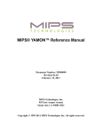
Chapter 5
DDR2 SDRAM Controller
The SEAD-3 Basic RTL uses the DDR2 SDRAM controller from Xilinx. The DDR2 SDRAM is not full-featured
with respect to all the different configurations of DDR2-SDRAM SODIMMs on the market, but is limited to support
single rank/sided SODIMMs only. In order to use the complete DRAM address space on SEAD-3 board, a
512-MByte single rank SODIMM is required.
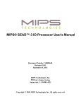
Figure 5.1 DDR2 SDRAM Controller Block Diagram
XILINX
DDR2 SDRAM
CPU Master
Controller
Master
USB-2.0 HS
Controller
USB Bus
App Bus
PHYSICAL LAYER
DDR2 SDRAM
Interface
CONTROLLER
X-bus Target#0
USER INTERFACE
X-Bus
Controller
DDR2 Bus
Figure 5.1 illustrates SEAD-3 Basic RTL implementation of DDR2 SDRAM module. There are two master data ports
and one master register port in the interface controller. The CPU accesses the memory controller from a master data
port or a master register port. USB access to the memory controller is only from a master data port. CPU access
DDR2 SDRAM Interface controller registers from a register port. All data port accesses are forwarded to the Xilinx
DDR2 SDRAM controller. USB will have highest priority to access memory, only exception is when cpu has started
a burst read or write transaction. ??
The DDR2-SDRAM controller can be accessed from the USB or CPU—USB has the higher priority, though if the
CPU is in the middle of a burst access, USB must wait until the burst trasaction is complete.
USB access will then have to wait for burst transaction to complete in the interface controller. The transaction is signalled as complete when it is forwarded to the DDR2 SDRAM controller. The RTL source, User Guide, and implementation details can be obtained from www.xilinx.com. Memory Interface Generator (MIG) utility is invoked from
Xilinx Coren to generate DDR2 Controller. DDR2 controller is configured to work with Micron SODIMM
mt4htf3264hy_667. However, controller has been tested using SODIMM (single rank, upto 512MB, CAS 5) from
other vendors.
MIPS® SEAD™-3 Basic RTL User’s Manual, Revision 01.00
Copyright © 2009, 2010 MIPS Technologies Inc. All rights reserved.
31
DDR2 SDRAM Controller
5.1 CPU Accessible Registers
The internal register maps and programming details for the DDR2 SDRAM device installed in the DDR2 SDRAM
SODIMM socket are listed in Table 5.1. The DDR2 SDRAM controller module has 53 presence detection registers
that are accessible by the CPU via the X-bus:
Table 5.1 DDR2 SDRAM Controller Module Registers, BASE = 0x1B00.0000
Name
Offset Address
Access
Function
SD_SPDCNF
0x0040
R/W
Presence Detect Configuration
SD_SPDADR
0x0048
R/W
Presence Detect Read Address register
SD_SPDDAT
0x0050
RO
Presence Detect Read Data register
5.1.1 DDR2 SDRAM Presence Detected Configuration
Name:
Address:
Access:
Reset Value:
SD_SPDCNF
0x1B00.0040
R/W
0x00000000
Table 5.2 SD_SPDCNF Register
Bits
31:10
9:0
Field name
Function
Initial value
Reserved
CPDIV
N/A
Clock Down Scale Factor
0x0
This register must be set by software to specify the clock down scale for the Serial Presence Detect controller.
The SPD controller must run at a lower clock frequency to provide safe timing margins at the serial interface.
To achieve a safe clock rate to the EEPROM, CPDIV should be set to 10*gclk(frequency in MHz), for example,
gclk==83Mhz => CPDIV=830
5.1.2 DDR2 SDRAM Presence Detected Read Address Register
Name:
Address:
Access:
Reset Value:
SD_SPDADR
0x1B00.0048
R/W
0x00000000
Table 5.3 SD_SPDADR register
Bits
Field name
31:8
Reserved
7:0
RDADR
Function
Initial value
N/A
Read Address
0x0
The SD_SPDCNF register must be set before accessing this register.
32
MIPS® SEAD™-3 Basic RTL User’s Manual, Revision 01.00
Copyright © 2009, 2010 MIPS Technologies Inc. All rights reserved.
5.1 CPU Accessible Registers
5.1.3 DDR2 SDRAM Presence Detected Transfer Register
Name:
Address:
Access:
Reset Value:
SD_SPDDAT
0x1B00.0050
RO
0x00000000
Table 5.4 SD_SPDDAT Register
Bits
Field name
Function
Initial value
31:10
Reserved
N/A
9
RDERR
Missing acknowledge from EEPROM
0x0
8
BUSY
Read Access in progress
0x0
7:0
RDATA
Read Data
0x0
The SD_SPDCNF register must be set before accessing this register.
Software can read DDR2 SDRAM SODIMM configuration data from the SODIMM Serial EEPROM in this register.
To do so, the software must write the desired read (byte-) address to the SD_SPDADR register. This will trigger the
SPD controller to read data from this address in the SODIMM EEPROM; while processing, the BUSY bit is set to
one. When the BUSY bit has returned to zero, read data will be presented in the RDATA field. The RDERR bit is set
if read data is corrupted.
MIPS® SEAD™-3 Basic RTL User’s Manual, Revision 01.00
Copyright © 2009, 2010 MIPS Technologies Inc. All rights reserved.
33
DDR2 SDRAM Controller
34
MIPS® SEAD™-3 Basic RTL User’s Manual, Revision 01.00
Copyright © 2009, 2010 MIPS Technologies Inc. All rights reserved.
Chapter 6
USB-HS 2.0 Controller
The SEAD-3 Basic RTL supports the BVCI interface to the Synopsys USB-HS 2.0 OTG controller. The USB-HS 2.0
Interface controller has one master port and one slave port. CPU accesses USB-HS 2.0 controller registers using slave
port. Master port is used for memory data transfer. Figure 6.1 illustrates the interface of US-HS 2.0 OTG controller
Figure 6.1 USB-HS 2.0 Controller Block Diagram
TARGET
Synopsys
USB-HS 2.0
Controller
BVCI
USB X-BUS
Slave
Interface
X-bus
Target # 2
VUSBHS
CORE
INITIATOR
ULPI
USB BVCI
Interface Controller
BVCI
USB DDR2
Master
Interface
EC/AHB/OCP Bus
X-BUS
Controller
X-bus
Target #0
X-bus USB
DDR2 SDRAM
Controller
DDR2 SDRAM
Bus
Dual Port SRAM
6.1 CPU-accessible USB Registers
Slave accesses from the CPU enables access to the configuration, control, and status registers. The USB register base
address is 0x1b20.0000. Register offset definitions are listed in Table 6.1 below.
Configuration, control, and status registers are divided into three categories: identification, capability, and operational.
MIPS® SEAD™-3 Basic RTL User’s Manual, Revision 01.00
Copyright © 2009, 2010 MIPS Technologies Inc. All rights reserved.
35
USB-HS 2.0 Controller
Identification registers are used to declare the slave interface presence along with complete set of the hardware configuration parameters.
Static, read-only registers define the software limits, restrictions, and capabilities of the host/device controller.
Operational registers consists of dynamic control and status registers that may be read-only, read/write, or read/write
to clear.
EHCI registers are listed along side device registers to show the complementary nature of host and device control.
Host-mode EHCI compatibility registers begin at offset 0x100.
Table 6.1 USB Slave Interface Register Sets Base at 0x1b20.0000
Address Offset
Register Set
Function
0x000 to 0x0FC Identification Registers
Slave Interface Presence, Hardware configuration parameters
0x100 to 0x124
Capabilities, limits, and restrictions
of a host/device controller implementation
Capability Registers
0x140 to 0x1FC Operational Registers
Control and monitor operational
state of the host/device controller
Refer to the Synopsys document
CI13420_CI13520_CI13620_CI13720_IPCS_PM_HighSpeedControllerCore_20A.pdf for a detailed descriptions of
all registers,
36
MIPS® SEAD™-3 Basic RTL User’s Manual, Revision 01.00
Copyright © 2009, 2010 MIPS Technologies Inc. All rights reserved.
Chapter 7
Interrupt Controller
The SEAD-3 Basic RTL supports an interface to the MIPS Global Interrupt Controller (GIC). The GICPresent bit in
the SEAD3_CFG register (0x1B10.0110) indicates the presence or absence of the GIC.
When the GIC option is not selected, board and controller interrupts are directly mapped to processor interrupts, as
shown in Table 7.1
Table 7.1 Direct Mapped Interrupt Scheme
System Interrupts
Description
CPU Interrupts
PIC32 (gpioa, gpiob, spi), USB
Interrupts from PIC32 and USB controller
SI_Int[0]
I2C RTC
Interrupt from Real Time Clock on I2C bus
SI_Int[1]
uart #0, uart #1
UART interrupts on Peripheral bus
SI_Int[2]
NEWSC Switch
Activity detected on NEWSC switch
SI_Int[3]
Ethernet
Interrupt from Ethernet controller
SI_Int[4]
SI_TimerInt
Timer Interrupt from processor
SI_Int[5]
7.1 MIPS Global Interrupt Controller (GIC) Interface
The Global Interrupt Controller (GIC) is mapped to X-bus Target #1 address space (see Chapter 3, “Memory Map and
Register Access Rules” on page 15. The GIC base address on the SEAD-3 board is 0x1B1C.0000.
The GIC is configured as follows:
• 1 VPE
• 24 global interrupt sources
• Supports EIC or direct mapping
• Local Software, Timer, and Performance Counter interrupts
Refer to the MIPS Global Interrupt Controller User’s Manual [4] for a description of the GIC and programming
details.
Figure 7.1 illustrates the SEAD-3 Basic RTL interface to the GIC.
The EIC Mode in the GIC is disabled on reset. Software can enable EIC mode by setting the EICPresent bit in the
Soft Endian Register. Writes to this register reset the board, and on resumption, software can enable EIC Mode in the
GIC.
MIPS® SEAD™-3 Basic RTL User’s Manual, Revision 01.00
Copyright © 2009, 2010 MIPS Technologies Inc. All rights reserved.
37
Interrupt Controller
Figure 7.1 Interrupt Interface to GIC
X-BUS
Controller
X-Bus
Target #1
Internal
Interrupt
Controller
System
Interrupts
MIPS
Global
Interrupt
Controller
(GIC)
OCP
SI_Int
MIPS
CPU
Processor
GIC_INT
Interrupts
SI_EICPresent
Soft Endian Register
System and processor interrupts are mapped to the GIC source pins as shown in Table below.
Table 7-1 GIC Global Interrupt Source Pin Mapping
38
System Interrupt
Global Interrupt
Source
PIC32 GPIO Port A Interrupt
GIC_Int[8]
PIC32 GPIO Port B Interrupt
GIC_Int[7]
PIC32 SPI Interrupt
GIC_Int[6]
USB-HS 2.0 Controller Interrupt
GIC_Int[5]
I2C RTC Interrupt
GIC_Int[4]
UART device #1 Interrupt
GIC_Int[3]
UART device # 0 Interrupt
GIC_Int[2]
NEWS Switch Interrupt
GIC_Int[1]
Ethernet Controller Interrupt
GIC_Int[0]
MIPS® SEAD™-3 Basic RTL User’s Manual, Revision 01.00
Copyright © 2009, 2010 MIPS Technologies Inc. All rights reserved.
Appendix A
References
1
MIPS® SEAD™-3 Basic RTL Reference Manual
MIPS Document: MD00692
2
MIPS® SEAD™-3 Board User’s Manual
MD00682
MIPS Technologies, Inc.
3
SEAD™-3 Board Getting Started
MIPS Document: MD00687
4
MIPS® Global Interrupt Controller User's Manual
MIPS Document: MD00695
5
USB 2.0 High Speed Controller
CI13720
Synopsys
6
Memory Interface Generator (MIG) User Guide
UG086
Xilinx Corporation
MIPS® SEAD™-3 Basic RTL User’s Manual, Revision 01.00
Copyright © 2009, 2010 MIPS Technologies Inc. All rights reserved.
39
References
40
MIPS® SEAD™-3 Basic RTL User’s Manual, Revision 01.00
Copyright © 2009, 2010 MIPS Technologies Inc. All rights reserved.
Appendix B
Revision History
Change bars (vertical lines) in the margins of this document indicate significant changes in the document since its last
release. Change bars are removed for changes that are more than one revision old.
This document may refer to Architecture specifications (for example, instruction set descriptions and EJTAG register
definitions), and change bars in these sections indicate changes since the previous version of the relevant Architecture
document.
Revision
Date
Comments
01.00
March 10, 2010
Initial release
MIPS® SEAD™-3 Basic RTL User’s Manual, Revision 01.00
Copyright © 2009, 2010 MIPS Technologies Inc. All rights reserved.
41