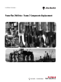
1
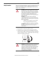
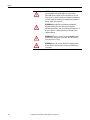
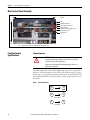
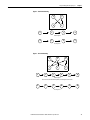
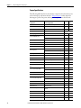
Installation Instructions
PowerFlex 700 Drive - Frame 7 Components Replacement
Important User Information
Solid-state equipment has operational characteristics differing from those of electromechanical equipment. Safety
Guidelines for the Application, Installation and Maintenance of Solid State Controls (publication SGI-1.1 available from
your local Rockwell Automation sales office or online at http://www.rockwellautomation.com/literature/) describes some
important differences between solid-state equipment and hard-wired electromechanical devices. Because of this difference,
and also because of the wide variety of uses for solid-state equipment, all persons responsible for applying this equipment
must satisfy themselves that each intended application of this equipment is acceptable.
In no event will Rockwell Automation, Inc. be responsible or liable for indirect or consequential damages resulting from the
use or application of this equipment.
The examples and diagrams in this manual are included solely for illustrative purposes. Because of the many variables and
requirements associated with any particular installation, Rockwell Automation, Inc. cannot assume responsibility or
liability for actual use based on the examples and diagrams.
No patent liability is assumed by Rockwell Automation, Inc. with respect to use of information, circuits, equipment, or
software described in this manual.
Reproduction of the contents of this manual, in whole or in part, without written permission of Rockwell Automation,
Inc., is prohibited.
Throughout this manual, when necessary, we use notes to make you aware of safety considerations.
WARNING: Identifies information about practices or circumstances that can cause an explosion in a hazardous environment,
which may lead to personal injury or death, property damage, or economic loss.
ATTENTION: Identifies information about practices or circumstances that can lead to personal injury or death, property
damage, or economic loss. Attentions help you identify a hazard, avoid a hazard, and recognize the consequence.
SHOCK HAZARD: Labels may be on or inside the equipment, for example, a drive or motor, to alert people that dangerous
voltage may be present.
BURN HAZARD: Labels may be on or inside the equipment, for example, a drive or motor, to alert people that surfaces may
reach dangerous temperatures.
IMPORTANT
Identifies information that is critical for successful application and understanding of the product.
Allen-Bradley, Rockwell Software, Rockwell Automation, and TechConnect are trademarks of Rockwell Automation, Inc.
Trademarks not belonging to Rockwell Automation are property of their respective companies.
Table of Contents
Important User Information . . . . . . . . . . . . . . . . . . . . . . . . . . . . . . . . . . . . . . . 2
Summary of Changes
New and Updated Information. . . . . . . . . . . . . . . . . . . . . . . . . . . . . . . . . . . . . 5
Preface
Introduction . . . . . . . . . . . . . . . . . . . . . . . . . . . . . . . . . . . . . . . . . . . . . . . . . . . . . . 7
Component Kits . . . . . . . . . . . . . . . . . . . . . . . . . . . . . . . . . . . . . . . . . . . . . . . . . . 7
Recommended Tools . . . . . . . . . . . . . . . . . . . . . . . . . . . . . . . . . . . . . . . . . . . . . . 8
Safety Precautions . . . . . . . . . . . . . . . . . . . . . . . . . . . . . . . . . . . . . . . . . . . . . . . . . 9
Important Initial Steps . . . . . . . . . . . . . . . . . . . . . . . . . . . . . . . . . . . . . . . . . . . 11
Chapter 1
Component Diagrams and Torque
Specs
Drive Components . . . . . . . . . . . . . . . . . . . . . . . . . . . . . . . . . . . . . . . . . . . . . . .
Inverter Section . . . . . . . . . . . . . . . . . . . . . . . . . . . . . . . . . . . . . . . . . . . . . . . . . .
Main Control Panel Assembly. . . . . . . . . . . . . . . . . . . . . . . . . . . . . . . . . . . . .
Fastener Torque Specifications . . . . . . . . . . . . . . . . . . . . . . . . . . . . . . . . . . . .
Torque Sequence . . . . . . . . . . . . . . . . . . . . . . . . . . . . . . . . . . . . . . . . . . . . .
Torque Specifications . . . . . . . . . . . . . . . . . . . . . . . . . . . . . . . . . . . . . . . . .
13
15
16
16
16
18
Chapter 2
Basic Component Removal
Procedures
Remove Main Control Panel Assembly. . . . . . . . . . . . . . . . . . . . . . . . . . . . .
Remove Stacking Panel . . . . . . . . . . . . . . . . . . . . . . . . . . . . . . . . . . . . . . . . . . .
Remove Precharge Board Assembly . . . . . . . . . . . . . . . . . . . . . . . . . . . . . . . .
Remove Transitional Bus Bar. . . . . . . . . . . . . . . . . . . . . . . . . . . . . . . . . . . . . .
21
22
23
23
Chapter 3
Component Replacement Procedures Precharge Board. . . . . . . . . . . . . . . . . . . . . . . . . . . . . . . . . . . . . . . . . . . . . . . . . . 25
Main Control Board. . . . . . . . . . . . . . . . . . . . . . . . . . . . . . . . . . . . . . . . . . . . . .
T-Comm Board . . . . . . . . . . . . . . . . . . . . . . . . . . . . . . . . . . . . . . . . . . . . . . . . . .
Switch Mode Power Supply Board . . . . . . . . . . . . . . . . . . . . . . . . . . . . . . . . .
Power Interface Board . . . . . . . . . . . . . . . . . . . . . . . . . . . . . . . . . . . . . . . . . . . .
Fan . . . . . . . . . . . . . . . . . . . . . . . . . . . . . . . . . . . . . . . . . . . . . . . . . . . . . . . . . . . . .
Fan Transformer . . . . . . . . . . . . . . . . . . . . . . . . . . . . . . . . . . . . . . . . . . . . . . . . .
Current Transducer . . . . . . . . . . . . . . . . . . . . . . . . . . . . . . . . . . . . . . . . . . . . . .
Inverter Snubber Board . . . . . . . . . . . . . . . . . . . . . . . . . . . . . . . . . . . . . . . . . . .
Inverter Snubber Resistor . . . . . . . . . . . . . . . . . . . . . . . . . . . . . . . . . . . . . . . . .
Inverter Power Module (IGBT) . . . . . . . . . . . . . . . . . . . . . . . . . . . . . . . . . . .
Main Control Panel Thermal Sensor. . . . . . . . . . . . . . . . . . . . . . . . . . . . . . .
Heatsink Thermal Sensor . . . . . . . . . . . . . . . . . . . . . . . . . . . . . . . . . . . . . . . . .
Bus Fuse . . . . . . . . . . . . . . . . . . . . . . . . . . . . . . . . . . . . . . . . . . . . . . . . . . . . . . . . .
Bus Capacitor. . . . . . . . . . . . . . . . . . . . . . . . . . . . . . . . . . . . . . . . . . . . . . . . . . . .
Converter Snubber Board - AC Input Only . . . . . . . . . . . . . . . . . . . . . . . .
Converter Power Module (SCR) - AC Input Only . . . . . . . . . . . . . . . . . .
MOV - AC Input Only . . . . . . . . . . . . . . . . . . . . . . . . . . . . . . . . . . . . . . . . . . .
DC Link Choke - AC Input Only . . . . . . . . . . . . . . . . . . . . . . . . . . . . . . . . .
Precharge SCR Module Snubber Board - DC Input Only. . . . . . . . . . . .
Precharge SCR Module - DC Input Only . . . . . . . . . . . . . . . . . . . . . . . . . .
Rockwell Automation Publication 20B-IN017B-EN-P - September 2011
26
27
30
31
32
35
35
38
40
42
45
46
48
49
50
51
54
55
56
57
3
Table of Contents
Notes:
4
Rockwell Automation Publication 20B-IN017B-EN-P - September 2011
Summary of Changes
This manual contains new and updated information.
New and Updated
Information
This table contains the changes made to this revision.
Topic
Page
Added Heatsink Fan Transformer kit, 1336-T-SP5A, to table of component kits.
(Instructions were already in this manual, but the kit was not listed in the table.)
7
Added T-Comm Board kit, SK-G9-TCOMM, to table of component kits.
7
Added T-Comm Board removal and installation instructions.
27
Rockwell Automation Publication 20B-IN017B-EN-P - September 2011
5
Summary of Changes
Notes:
6
Rockwell Automation Publication 20B-IN017B-EN-P - September 2011
Preface
Introduction
This publication provides guidelines for replacing the major components in the
PowerFlex 700 Frame 7 drive.
Component Kits
All kits include necessary components, ESD wrist strap and hardware (if
required), and thermal grease (if required).
Description
Precharge Board
Heatsink Fan
Heatsink Fan Transformer
Current Transducer
Inverter Power Module (IGBT)
Kit Catalog No.
SK-G9-PRE1-V480
1336-PB-SP22C
SK-G9-VMCB1-D0
SK-G9-VMCB1-C0
SK-G9-TCOMM
SK-G9-PWRS1-D0
SK-G9-GDB1-D292
SK-G9-GDB1-D325
SK-G1-FAN1-F7
1336-T-SP5A
SK-G1-CT1-F7
SK-G1-QOUT1-F7
Inverter Snubber Kit
SK-G1-INVSNB1-F7
SCR Snubber Kit
SK-G1-SCRSNUBRB
Converter Power Module (SCR)
SK-G1-SCR1-F7
DC Precharge SCR Module
SK-G1-SCR2-F7
Thermal Sensors
SK-G1-THM1-F7
Bus Fuse
Bus Capacitor
MOV
DC Link Choke
Balancing Resistor
1336-F1-SP6A
SK-G1-BUSCAP1-F7
SK-G1-MOV1-F7
SK-G1-DCCHOKE1-F7
1336-RLOAD-SP4A
Main Control Board
T-Comm Board
Switch Mode Power Supply Board
Power Interface Board
Notes
AC input
DC input
115V I/O
24V I/O
292A Drives
325A Drives
480 to 120 Auto transformer (fan only)
Includes one Transducer.
Includes
·Two IGBTs.
·Two Gate Interface Boards.
Includes:
·One Snubber Board.
·One Resistor.
AC input requires three kits.
DC input requires one kit.
AC input.
Kit includes three SCR Modules.
DC input.
Kit includes one SCR Module
Includes:
·Main Control Panel Thermal Sensor
·Heatsink Thermal Sensor.
Includes one Capacitor.
AC input.
AC input.
Includes one Resistor.
Refer to the master parts list for the most up-to-date information:
http://www.ab.com/support/abdrives/powerflex70/PF7ReleasedParts.pdf
Rockwell Automation Publication 20B-IN017B-EN-P - September 2011
7
Preface
Recommended Tools
The following list of tools is provided for your reference to disassemble and
assemble the drive and components. This list may not be all-encompassing for
your situation. Not all tools are needed for some components. Refer to pertinent
sections for details.
Description
Notes
Torque wrench (metered in lb•in or N-m), T30 and T40 bits
Torque seal or colored marker
Screwdrivers (standard, Phillips, star – various sizes)
Magnetic screwdriver, long
Socket set, metric
Cylindrical pick-up magnet
Pliers, regular and needle-nose
Wire cutters
Volt ohm meter
Used to test Inverter Snubber Resistors
Isopropyl alcohol
Nylon tie wraps
Pencil
14 or 16 gauge wire, about 10 cm (4 in.)
Two (2) #10 wire lugs, either fork or ring
8
Rockwell Automation Publication 20B-IN017B-EN-P - September 2011
Needed whenever IGBT gates are exposed. Used to
short the gates.
Preface
Safety Precautions
The precautions and general installation requirements provided in the PowerFlex
700 Frame 7-10 Installation Instructions (publication 20B-IN014) and the
PowerFlex 700 User Manual (publication 20B-UM002) must be followed in
addition to those included here.
ATTENTION: To avoid an electric shock hazard, ensure that all power has
been removed before proceeding. In addition, before servicing, verify
that the voltage on the bus capacitors has discharged. Check the DC bus
voltage at the Power Terminal Block by measuring between the DC+ &
DC– terminals, between the DC+ terminal and the chassis, and
between the DC– terminal and the chassis. The voltage must be zero for
all three measurements.
ATTENTION: Remove power before making or breaking cable
connections. When you remove or insert a cable connector with power
applied, an electrical arc may occur. An electrical arc can cause personal
injury or property damage by:
· sending an erroneous signal to your system’s field
devices, causing unintended machine motion.
· causing an explosion in a hazardous environment.
ATTENTION: Electrical arcing causes excessive wear to contacts on both
the module and its mating connector. Worn contacts may create
electrical resistance.
1. Turn off and lock out input power. Wait five minutes.
2. Verify that there is no voltage at the drive’s input power terminals.
3. Check the DC bus voltage at the Power Terminal Block by measuring
between the DC+ and DC– terminals, between the DC+ terminal and
the chassis, and between the DC– terminal and the chassis. The voltage
must be zero for all three measurements.
L1
L2
L3
I
O
ATTENTION: This assembly contains parts and sub-assemblies that are
sensitive to electrostatic discharge. Static control precautions are
required when servicing this assembly. Component damage may result
if you ignore electrostatic discharge control procedures. If you are not
familiar with static control procedures, reference Allen-Bradley
Publication 8000-4.5.2 Guarding Against Electrostatic Damage, or any
other applicable ESD protection handbook.
Rockwell Automation Publication 20B-IN017B-EN-P - September 2011
9
Preface
ATTENTION: The information in this publication is merely a guide for
proper installation. Rockwell Automation, Inc. cannot assume
responsibility for the compliance or the noncompliance to any code
(national, local, or otherwise) for the proper installation of this drive or
associated equipment. A hazard of personal injury and/or equipment
damage exists if codes are ignored.
ATTENTION: Only qualified personnel familiar with adjustable
frequency AC drives and associated machinery should plan or
implement the installation, start-up, and subsequent maintenance of
the system. Failure to comply may result in personal injury and/or
equipment damage.
ATTENTION: HOT surfaces can cause severe burns. Do not touch the
heatsink surface during operation of the drive. After disconnecting
power, allow time for cooling.
ATTENTION: Replace all protective shields before applying power to
the drive. Failure to replace protective shields may result in death or
serious injury.
10
Rockwell Automation Publication 20B-IN017B-EN-P - September 2011
Preface
Important Initial Steps
Read and follow these statements before performing any service on the drive.
· Read and follow the precautions in Safety Precautions on page 9.
· Identify components to be replaced using the figures in Component
Diagrams and Torque Specs on page 13.
· Remove protective shields only as necessary.
· Before disconnecting any wire or cable, verify that it is labeled. Also, when
removing components, note hardware type and location.
· When torquing any fasteners, use a colored marker or torque seal to mark
each screw after torquing so you know when all are done and to indicate
signs of any subsequent tampering.
· Refer to the product installation documentation for startup and other
instructions after servicing.
Rockwell Automation Publication 20B-IN017B-EN-P - September 2011
11
Preface
Notes:
12
Rockwell Automation Publication 20B-IN017B-EN-P - September 2011
Chapter
1
Component Diagrams and Torque Specs
AC input drive is shown.
Drive Components
Transitional Bus Bar
HIM
Gate Interface Board (U)
(V and W not shown)
Current Transducer
Inverter Snubber Boards (U,
V, W)
Bus Fuse
! CAUTION
HOT SURFACES
PE
ALLEN-BRADLEY
U
V
W
J1
DC Link Choke
DANGER
RISK OF SHOCK
REPLACE AFTER
SERVICING
Converter Snubber Boards (3)
with Converter Power SCR
Modules underneath
Precharge Board
Assembly
Capacitor
for Fan
AC Bus Bars (R, S, T)
Transformer
MOV Location
PE
R-L1
S-L2
T-L3
U-M1
V-M2
W-M3
W Phase
PE
V Phase
-DC
TORQUE LARGE TERMINALS TO 10 N-m (87LB-IN)
T Phase
+DC
USE 75° COPPER WIRE ONLY
U Phase
Power Terminal Block
S Phase
!
Inverter Snubber Resistors
J2
R Phase
J3
Motor Bus Bars
Balancing Resistors
TB11
MADE IN U.S.A.
Inverter Power Module IGBTs
(U, V, W) (under Inverter
Snubber Board)
Communications
Module
TB11
25 AMPERES RMS
MAXIMUM
TB2
Switch Mode Power Supply Board (under Power Interface Board
(under Main Control Panel)
Main Control Panel)
Main Control
Panel Thermal
Sensor
Heatsink Thermal
Sensor location
Main Control Panel
(Stacking Panel (underneath)
Main Control Panel Assembly
DC Capacitor Bank
(under Transitional Bus Bar)
AC Power Input
Connections
Motor
Connections
Rockwell Automation Publication 20B-IN017B-EN-P - September 2011
13
Chapter 1
Component Diagrams and Torque Specs
AC input drive is shown.
DC Capacitor Bank
(under Transitional Bus Bar)
Current Transducer
(quantity: 3)
Heatsink Thermal
Sensor location
Gate Interface Board
Transitional Bus Bar
Inverter Snubber Board (U)
(V and W not visible in this image)
Inverter Power Module IGBT (U)
(V and W below U)
IGBT Gate Harness and
CT Harness
Bus Fuse
U
Motor Bus Bars (U, V, W)
V
Power Interface Board
location (under Main
Control Panel)
W
Main Control Panel Thermal Sensor
Wire
Ribbon Cable - Main
Control Board to Power
Interface Board
HIM
(Blank shown on this Drive)
Ribbon Cable Main Control Board
to Comm Board
Main Control Board
(under HIM mounting)
DC Link Choke
Communications Panel
Switch Mode Power
Supply Board (under
Main Control Panel)
Main Control Panel
TB11
Capacitor for Fan
Transformer
Precharge Board Assembly
MOV Location
AC Power Input Connections
14
W Phase
V Phase
U Phase
T Phase
S Phase
R Phase
Power Terminal Block
Motor Connections
Rockwell Automation Publication 20B-IN017B-EN-P - September 2011
Component Diagrams and Torque Specs
Chapter 1
Inverter Section
Current Transducers
Current Transducer Mounting Clamps
Inverter Snubber Boards
Motor Bus Bars
Gate Interface Boards
Inverter Power Module IGBTs
Bottom of Drive
Top of Drive
Current Transducers
(behind Mounting Clamps)
Motor Bus Bars
Inverter Snubber Boards
IGBT Bus Bars
Gate Interface Boards
Inverter Power Module IGBTs
Note: Components are shown as seen from right side without drive covers.
Rockwell Automation Publication 20B-IN017B-EN-P - September 2011
15
Chapter 1
Component Diagrams and Torque Specs
Main Control Panel Assembly
Bottom of Drive
Top of Drive
Components are listed left to right for
each level
Front
HIM
Communications Panel
TB11 and Main Control Board
Main Control Panel
Switch Mode Power Supply Board and
Power Interface Board
Stacking Panel
Back
Note: Components are shown as seen from right side without drive covers.
Fastener Torque
Specifications
Torque Sequence
ATTENTION: When mounting components to a drive’s heat sink,
component fastener torque sequences and tolerances are crucial to
component-to-heat sink heat dissipation.
Components can be damaged if initial tightening procedure is not
performed to specification.
The following illustrates initial and final tightening sequences for components
fastened to a heat sink using two, four, and six screws. Initial torque is 1/3 (33%)
of final torque, except six-point mountings, which require 0.7 N•m (6 lb•in) The
numeric illustration labels are for your assistance. Drive components do not carry
these labels.
Figure 1 - Two-Point Mounting
1
2
1
2
Initial Sequence
2
1
Final Sequence
16
Rockwell Automation Publication 20B-IN017B-EN-P - September 2011
Component Diagrams and Torque Specs
Chapter 1
Figure 2 - Four-Point Mounting
1
3
4
2
2
1
3
4
2
1
Initial Sequence
4
3
Final Sequence
Figure 3 - Six-Point Mounting
1
2
6
2
4
3
1
5
3
4
5
6
Initial Sequence
Do not exceed 0.7 Newton-meters (6 lb•in) on initial torque of all six screws.
1
2
3
4
5
6
Final Sequence
Rockwell Automation Publication 20B-IN017B-EN-P - September 2011
17
Chapter 1
Component Diagrams and Torque Specs
Torque Specifications
The following table lists fastener locations by component, how the fasteners are
used, and torque specifications. Refer to Torque Sequence in this chapter for
fastening two-point, four-point, and six-point components to the heat sink.
Component
Fastener Application
Torque
lb•in
Torque
N•m
Fan Motor
Motor to Fan Cover Assembly
14
2
Fan Cover Assembly
Assembly to chassis
26
3
3
Fan Transformer
Transformer to chassis
26
Fan Capacitor
Capacitor to chassis
Hand tighten
MOV Surge Suppressor
MOV to chassis
14
2
6
0.7
Resistor to heat sink
Inverter Snubber Resistor
Final sequence: 26
3
Inverter Snubber Resistor
Wires to Capacitor Bus Bar Assembly
50
6
Inverter Snubber Bracket
Bracket to Power Module
80
9
Inverter Snubber Board
Board to Brackets
50
6
Converter Snubber Board
Board to Input Rectifier
50
6
6
0.7
Resistor to heat sink
Balancing Resistor
Initial sequence:
Final sequence: 26
3
Balancing Resistor
Wires to Capacitor Bus Bar Assembly
50
6
Heatsink Thermal Sensor
Thermistor to heatsink
14
2
Bus Capacitor Holder
Holder to Bus Capacitors
26
3
Capacitor Bus Bar Assembly
Assembly to Bus Capacitors
50
6
Gate Interface Board
Board to Power Modules
14
2
Inverter Power Module (IGBT) Bus
Bar
Bus Bar to Power Modules
80
9
6
0.7
Module to heat sink
Inverter Power Module (IGBT)
Initial sequence:
Final sequence: 32
3.6
DIN Rail (TB1)
Rail to chassis
50
6
PE Shortening Bar
Bar to TB1
80
9
6
0.7
SCR to heat sink
Converter Power Module (SCR)
18
Initial sequence:
Initial sequence:
Final sequence: 50
6
Transitional Bus Bar Assembly
Assembly to Power Module Bus Bar Assembly
80
9
Bus Fuse F1
Fuse to Transitional Bus Bar
80
9
DC Bus Inductor L1
Inductor to chassis
50
6
Bus Bar Cable Adaptor
Adaptor to Transitional Bus Bar and DC Bus
Inductor
80
9
Converter Bus and Motor Bus Bars
Bus Bars to all connections
80
9
Wires (PE)
Wires to Ground Stud
80
9
Wires
Wires to TB1
80
9
Wire (TE)
Wire to TB1
50
6
Rockwell Automation Publication 20B-IN017B-EN-P - September 2011
Component Diagrams and Torque Specs
Chapter 1
Component
Fastener Application
Torque
lb•in
Torque
N•m
Wires
Wires to TB2
7
0.8
Wires
Wires to TB3
8 – 10
0.9 – 1.1
CT Mounting Plate
Mounting Plate to CT Clamping Plate
14
2
CT Clamping Plate
Clamping Plate to Bus Bar
26
3
Power Cables
Cables to terminals
80
9
Main Control, Gate Driver, Precharge
Board Mounting Plates
Plates to chassis
26
3
High Voltage Guard
Guard to chassis
26
3
Rockwell Automation Publication 20B-IN017B-EN-P - September 2011
19
Chapter 1
Component Diagrams and Torque Specs
Notes:
20
Rockwell Automation Publication 20B-IN017B-EN-P - September 2011
Chapter
2
Basic Component Removal Procedures
The procedures in this section are required by many of the replacement
procedures described in this manual in addition to replacement of these
components themselves.
DO NOT perform any of the procedures in this section unless specified by the
instructions for the component you are replacing.
Remove Main Control Panel
Assembly
Refer to the figures in Component Diagrams and Torque Specs on page 13 for
these instructions.
Remove Components
1. Read and follow the Safety Precautions on page 9 and Important Initial
Steps on page 11.
2. Remove safety shields as needed.
3. Remove the ribbon cable going from the Main Control Board ( J2) to
the Power Interface Board ( J1).
4. Remove the two screws on the Main Control Panel below TB11 for the
Main Control Board.
5. Verify that all wiring to lower side of TB11 is properly labeled and then
disconnect wiring from TB11.
Rockwell Automation Publication 20B-IN017B-EN-P - September 2011
21
Chapter 2
Basic Component Removal Procedures
6. Remove the two nuts at the top of the Main Control Panel.
! CAUTION
HOT SURFACES
7. Remove Main Control Panel; support.
8. Disconnect wire harnesses from TB11 to the Switch Mode Power
Supply Board ( J4 connector) and at TB1 and TB2 on the Power
Interface Board.
9. Label and disconnect all customer wiring from TB11.
10. Carefully set the Main Control Panel aside.
Install Components
When instructed for the component you are replacing, reinstall the Main
Control Panel Assembly components in the reverse order of removal.
Remove Stacking Panel
Refer to the figures in Component Diagrams and Torque Specs on page 13 for
these instructions.
Remove Components
1. Perform Remove Main Control Panel Assembly on page 21.
2. Remove remaining wiring harnesses from the Power Interface Board. Do
not disconnect the wiring between the Power Interface Board and the
Switch Mode Power Supply Board.
Connector
Connected Components
J14, J15, J16
U, V, W Phase CT
J24
+Bus IN of Power Interface Board to J1 of Precharge Board
J7
Main Control Panel Thermal Sensor
J18
U, V, W negative gates
J23
U, V, W positive gates
3. Disconnect the Main Control Panel Assembly Thermal Sensor wire
from the Monitor Wire. (See diagram at the start of Main Control Panel
Thermal Sensor on page 45.)
4. Remove the two screws at the bottom of the Stacking Panel for the
Power Interface and the Switch Mode Power Supply Boards. Remove the
panel by sliding it up and out.
22
Rockwell Automation Publication 20B-IN017B-EN-P - September 2011
Basic Component Removal Procedures
Chapter 2
Install Components
When instructed for the component you are replacing, reinstall the Stacking
Panel components in the reverse order of removal.
Refer to the figures in Component Diagrams and Torque Specs on page 13 for
these instructions.
Remove Precharge Board
Assembly
Remove Components
1. Read and follow the Safety Precautions on page 9 and Important Initial
Steps on page 11.
2. Using pliers if needed, remove the three (3) wiring/harnesses ( J1, J2, J3)
at the top of the board.
Note: Some connectors may not be labeled. Be sure to label them.
3. For DC input only: Verify that customer wiring to TB2 is properly
labeled and then disconnect wiring from TB2.
4. Unscrew the two mounting screws at the top of the mounting panel.
5. Slide the board and mounting plate out by pulling down and out.
Install Components
When instructed for the component you are replacing, reinstall the Precharge
Board Assembly components in the reverse order of removal.
Remove Transitional Bus Bar
Refer to the figures in Component Diagrams and Torque Specs on page 13 for
these instructions.
Remove Components
1. Read and follow the Safety Precautions on page 9 and Important Initial
Steps on page 11.
2. Remove the upper safety cover (four screws).
3. Locate the Transitional Bus Bar.
Rockwell Automation Publication 20B-IN017B-EN-P - September 2011
23
Chapter 2
Basic Component Removal Procedures
Remove these screws
Figure 4 - Screws on Panel over Transitional Bus Bar
TIP
When you remove the screws in the next step, you will remove
the Bus Fuse as well. There is a plate over the top end of the Bus
Fuse which will be free upon removal of the screws. Do not let
the plate fall.
4. Using Figure 4 -, remove the seventeen (17) screws for the Transitional
Bus Bar.
5. Slide the Transitional Bus Bar to the left and out.
This allows access to the wire connections below it if needed.
Install Components
When instructed for the component you are replacing, reinstall the Transitional
Bus Bar components in the reverse order of removal.
Only torque screws after all components are in place.
24
Rockwell Automation Publication 20B-IN017B-EN-P - September 2011
Chapter
3
Component Replacement Procedures
Precharge Board
Refer to the figures in Component Diagrams and Torque Specs on page 13 for
these instructions.
Remove Components
1. Read and follow the Safety Precautions on page 9 and Important Initial
Steps on page 11.
2. Remove the safety cover over the Precharge Board.
3. For DC input only: Verify that customer wiring to TB2 is properly
labeled and then disconnect wiring from TB2.
4. Using pliers if needed, remove the three (3) wiring/harnesses ( J1, J2, J3)
at the top of the board.
Note: Some connectors may not be properly labeled. Be sure to label
them appropriately.
5. Remove the Precharge Board mounting star screw located at the lower
left corner of the Precharge Board.
6. For AC input: Using your fingers or
needle-nose pliers, squeeze the wings
of each of the three spacers and
separate the Precharge Board from
the mounting plate.
7. For DC input: Turn each of the six
(6) lock screws 1/4 turn
counterclockwise to unlock.
Screw
8. Remove the Precharge Board.
Spacers
AC Input Shown
Install Components
1. Install the new Precharge Board.
2. Reconnect wiring.
3. Replace all safety shields and enclosure covers before applying power to
the drive.
Rockwell Automation Publication 20B-IN017B-EN-P - September 2011
25
Chapter 3
Component Replacement Procedures
Main Control Board
Refer to the figures in Component Diagrams and Torque Specs on page 13 for
these instructions.
Remove Components
1. Read and follow the Safety Precautions on page 9 and Important Initial
Steps on page 11.
2. Remove safety shields as needed.
Nuts
Communications Panel
(Located over Main Control Panel)
Ground Wire
Screws and Washers
Release Cable from
Clamp
Main Control Board
(Shown larger than in image above)
Ribbon
Cables
Screws
To TB11
3. Unscrew the green/yellow ground wire from the Communications
Panel.
4. Remove the two nuts and two screws and washers for the
Communications Panel.
5. Disconnect both ribbon cables from the left side of the Main Control
Board.
6. Holding the Communications Panel, release the cable at the bottom of
the panel from its clamp and set the Communications Panel aside.
7. If needed, unscrew and disconnect the wire set going to TB11 from the
Main Control Board.
8. Unscrew the six (6) screws holding the Main Control Board.
9. Remove the Main Control Board.
26
Rockwell Automation Publication 20B-IN017B-EN-P - September 2011
Component Replacement Procedures
Chapter 3
Install Components
1. Install the new Main Control Board.
2. Reassemble all components in the reverse order of removal.
3. Reconnect all cables.
4. Replace all safety shields and enclosure covers before applying power to
the drive.
T-Comm Board
See Component Diagrams and Torque Specs on page 13 to locate the component
detailed in these instructions.
Remove Components
1. Read and follow the Safety Precautions on page 9 and Important Initial
Steps on page 11.
2. Remove the Main Control Board:
a. Remove the HIM board from its slot (if used).
b. Disconnect the ribbon cable from the Main Control Board (connects
to J1on Power Interface Board).
c. Disconnect the wiring connector from the Main Control Board
(connects to 8-pin serial port in the lower-right corner of Main Control
Board panel).
d. Remove and save the grounding-wire screw (connects to PE on TB11).
e. Remove and save the two mounting screws for the Main Control
Board.
Rockwell Automation Publication 20B-IN017B-EN-P - September 2011
27
Chapter 3
Component Replacement Procedures
f. Remove the Main Control Board.
HIM Board slot
Ribbon Cable Connector
Mounting Screw
Ribbon Cable Connection to T-Comm Board
Wiring Connector
Grounding-Wire Screw
Optional 20-Comm-x Board Detail
Mounting Screws (4)
Mounting Screw
3. Remove the 20-Comm-x Board (if used):
a. Disconnect the ribbon cable between the 20-Comm-x Board and
T-Comm board; disconnect only from the T-Comm board.
b. Remove and save the four mounting screws.
4. If the 20-Comm-x Board is not used, remove the screw securing the
T-Comm grounding tab.
T-Comm grounding tab screw
T-Comm grounding tab flat
T-Comm grounding tab upright
5. Place the tip of a flathead screwdriver between the T-Comm grounding
tab and screw mount.
Gently pry up until the grounding tab is in an upright position or about 90
degrees from the screw mount.
28
Rockwell Automation Publication 20B-IN017B-EN-P - September 2011
Component Replacement Procedures
Chapter 3
6. If needed, use the same flathead screwdriver tip to pry the seven locking
tabs away from the T-Comm Board.
T-Comm Board Locking Tab Locations
Five locking tabs are on the back side of the Main Control Board (above); two are on the front side in the area between
the optional HIM and 20-Comm-x board slots (upper right).
NOTE: Use a flathead screwdriver tip to pry the locking tabs away from the T-Comm Board (lower right).
7. Remove the T-Comm Board from the Main Control Board; return or
dispose of it properly.
Install Components
1. Install the new T-Comm Board.
2. Verify the board is locked into all seven locking tabs.
3. Carefully bend the T-Comm grounding tab until it is flush with the screw
mount on the Main Control Board.
4. Reassemble all components in the reverse order of removal.
5. Reconnect all cables, safety shields and enclosure covers before applying
power to the drive.
Rockwell Automation Publication 20B-IN017B-EN-P - September 2011
29
Chapter 3
Component Replacement Procedures
Switch Mode Power Supply
Board
Refer to the figures in Component Diagrams and Torque Specs on page 13 for
these instructions.
Remove Components
1. Perform Remove Main Control Panel Assembly on page 21.
2. Disconnect all cables ( J2, J4, J3, J1) from the Switch Mode Power
Supply Board.
3. Remove the Switch Mode
Power Supply Board
mounting star screw
located at the lower right
corner of the board.
Spacers
4. Using your fingers or
needle-nose pliers, squeeze
Screw
the wings of each of the
three spacers and separate
the Switch Mode Power Supply Board from the mounting plate.
5. Remove the Switch Mode Power Supply Board.
Install Components
1. Install the new Switch Mode Power Supply Board.
Tighten board screws to 1.7 N•m (15 lb•in)
2. Reconnect all cables.
3. Reassemble all components in the reverse order of removal.
Tighten sheet metal screws to 3.2 N•m (28 lb•in)
4. Reconnect the ribbon cable going from the Power Interface Board ( J1)
to the Main Control Board ( J2).
5. Replace all safety shields and enclosure covers before applying power to
the drive.
30
Rockwell Automation Publication 20B-IN017B-EN-P - September 2011
Component Replacement Procedures
Power Interface Board
Chapter 3
Refer to the figures in Component Diagrams and Torque Specs on page 13 for
these instructions.
Remove Components
1. Read and follow the Safety Precautions on page 9 and Important Initial
Steps on page 11.
2. Perform Remove Main Control Panel Assembly on page 21.
3. Remove remaining wiring
harnesses from the Power
Interface Board, including the
wiring between the Power
Interface Board and the
Switch Mode Power Supply
Board.
J2
J1
TB1
J7
TB2
J10
J18
J16
J15
J14
J24
J23
J13
Connector
J12
Connected Components
J1
Main Control Board
J10
Precharge Board (only on DC input systems)
J16
W Phase CT
J15
V Phase CT
J14
U Phase CT
J24
+Bus IN of Power Interface Board
to J1 of Precharge Board
J13
Switch Mode Power Supply Board
J12
Switch Mode Power Supply Board
J23
U, V, W positive gates (upper phase)
J18
U, V, W negative gates (lower phase)
TB2
TB11
J7
Monitor Wire to thermal sensors
TB1
TB11
4. Remove the two Power Interface
Board mounting star screws
located at the upper right and
lower left corners of the board.
Screws
5. Using your fingers or needle-nose
pliers, squeeze the wings of each
of the nine (9) spacers and
remove the Power Interface Board
from the mounting plate.
Rockwell Automation Publication 20B-IN017B-EN-P - September 2011
31
Chapter 3
Component Replacement Procedures
Install Components
1. Install the new Power Interface Board.
Tighten board screws to 1.7 N•m (15 lb•in)
2. Reconnect all wiring except the ribbon cable going from the Power
Interface Board ( J1) to the Main Control Board ( J2).
3. Reinstall the Main Control Panel Assembly.
Tighten sheet metal screws to 3.2 N•m (28 lb•in)
4. Reconnect the ribbon cable going from the Power Interface Board ( J1)
to the Main Control Board ( J2).
5. Replace all safety shields and enclosure covers before applying power to
the drive.
Fan
The Fan is located behind the Main Control Panel assembly and Precharge
Board.
Fan Assembly
Refer to the figure below and the figures in Component Diagrams and Torque
Specs on page 13 for these instructions.
32
Rockwell Automation Publication 20B-IN017B-EN-P - September 2011
Component Replacement Procedures
Chapter 3
Remove Components
1. Read and follow the Safety Precautions on page 9 and Important Initial
Steps on page 11.
2. Perform Remove Main Control Panel Assembly on page 21.
3. Perform Remove Stacking Panel on page 22.
4. Perform Remove Precharge Board Assembly on page 23.
5. Verify that all wiring to Power Terminal Block is properly labeled and
then remove all nuts and disconnect accompanying wires from the
Power Terminal Block, including the DC+ and DC– Bus cables, the PE
jumper cable to chassis ground, and the PE Bus Bar (located over the
third and fourth Terminal Blocks).
TIP
For easier removal of the PE jumper cable, flex the cable to
relieve the strain on lug.
Remove these nuts
and wiring.
PE
DC–
DC+
Label and remove all
wiring here.
6. Remove the single screws on
the right end of U, V, and W
Current Transducer bus bars.
The Current Transducer
assemblies do not need to be
removed.
7. Remove the U, V, and W Bus
Bars.
To do so, move the top end of the bar to the right and the bottom end of
the bar to the left, pull down on a angle, then rotate the bar 180° and
fully remove the bar.
Rockwell Automation Publication 20B-IN017B-EN-P - September 2011
33
Chapter 3
Component Replacement Procedures
8. Remove the screws and accompanying wires for
R, S, and T Bus Bars at the SCR.
9. Remove the R, S, T Bus Bars.
TIP
Label Bus Bars for correct
orientation when reinstalling later.
10. Remove at least two terminal blocks from the
R, S, T Bus Bars at SCR
DIN rail by pushing down on the metal tab on
top of the terminal block while lifting the bottom of the terminal block
out toward you and up.
TIP
If desired for ease of access to individual terminal blocks,
remove barriers between terminal blocks by pulling out on a
slight down- or upward angle.
11. Remove the three screws for
the DIN rail, two toward the
left end and one at the right
end.
TIP
Slide remaining
terminal blocks
sideways as needed
to access screws.
Screws at Left End of DIN Rail
12. Remove the DIN rail.
13. Unplug Fan wire.
14. Remove the 12 screws at the exterior of
fan cover.
Do not remove screws near Fan cable at
this time.
15. Remove the Fan cover and the Fan.
You may need to pry the cover from the
drive enclosure.
16. Remove the four screws near Fan cable
that hold the Fan and cover together.
Install Components
1. If needed, remove the old gasket from Fan cover and replace gasket.
2. Mate cover and new Fan, positioning Fan cable in notch of opening in
cover.
34
Rockwell Automation Publication 20B-IN017B-EN-P - September 2011
Component Replacement Procedures
Chapter 3
3. Install the four screws that hold the Fan and cover together.
4. Place Fan unit in position, locating Fan
wire in bottom left corner.
5. Install the 12 screws at the exterior of
fan cover.
6. Reconnect Fan wire.
7. Reassemble remaining components in reverse order.
TIP
When replacing Motor Bus Bars, remove nearby terminal
block barriers to provide additional maneuvering space.
8. Replace all safety shields and enclosure covers before applying power to
the drive.
Fan Transformer
Refer to the figures in Component Diagrams and Torque Specs on page 13 for
these instructions.
Remove Components
1. Read and follow the Safety Precautions on page 9 and Important Initial
Steps on page 11.
2. Perform Remove Precharge Board Assembly on page 23.
3. Label and unscrew or disconnect wires for the Transformer.
4. Unscrew Transformer mounting brackets.
Install Components
1. Install new Transformer by screwing mounting brackets to drive.
2. Reconnect all wires and connectors for the Transformer.
3. Reassemble remaining components in reverse order.
4. Replace all safety shields and enclosure covers before applying power to
the drive.
Current Transducer
Refer to the figures in Component Diagrams and Torque Specs on page 13 for
these instructions.
Remove Components
1. Read and follow the Safety Precautions on page 9 and Important Initial
Steps on page 11.
2. Remove the safety cover.
Rockwell Automation Publication 20B-IN017B-EN-P - September 2011
35
Chapter 3
Component Replacement Procedures
3. Locate the Current Transducer to be replaced.
W Phase
V Phase
U Phase
4. Disconnect the wiring harness from the transducer board. Clip the wire
tie and remove the wiring harness.
5. Remove the three button
head screws that secure the
bus bar. Move the bus bar
and transducer to an ESDsafe flat surface for working
with it.
6. Using your fingers or
needle-nose pliers, squeeze
the wings of each of the
four spacers and separate
the transducer and board
from the mounting clamp.
Spacers
7. Loosen the two screws that
hold the two sections of the
CT mounting clamp, but
do not take the screws
completely out. Only
loosen them so that the end
is flush with the bottom of
the CT mounting clamp.
8. Remove mounting clamp
from the bus bar by sliding
the gentle bend of the bus
bar (the end with only one
screw hole) through the
assembly, taking care not to
damage the transducer or the insulation on the bus bar.
36
Rockwell Automation Publication 20B-IN017B-EN-P - September 2011
Component Replacement Procedures
Chapter 3
9. Remove transducer
assembly (transducer and
board) from the bus bar by
sliding the gentle bend of
the bus bar (the end with
only one screw hole)
through the assembly,
taking care not to damage
the insulation on the bus
bar or loosen the wiring.
Discard old transducer.
Install Components
1. Position the mounting bar with the end with two screw holes to your
right.
2. Orient the transducer with
the wiring socket away
Wiring
from you and its board to
Socket
your left. Slide transducer
onto the bus bar by sliding
the gentle bend of the bus
bar through the assembly, taking care not to damage the insulation on
the bus bar and not to loosen the wiring.
3. Orient the transducer
mounting clamp with the
smaller section on the
bottom and the notch
toward you.
Notch
4. Slide the mounting clamp
onto the bus bar by sliding
the gentle bend of the bus
bar (the end with only one screw hole) through the assembly, taking care
not to damage the insulation on the bus bar or loosen the wiring.
5. Attach the new transducer
to the spacers. Verify that
each spacer locks. Tighten
the clamp screws of the
mounting bracket finger
tight.
6. Position the CT assembly
and bus bar into place.
Tighten its three screws
and torque to 1.6 N•m (14
Spacers
lb•in.) Use a colored
marker or torque seal to mark each screw after torquing so you know
when all are done and to indicate signs of any tampering.
Rockwell Automation Publication 20B-IN017B-EN-P - September 2011
37
Chapter 3
Component Replacement Procedures
7. Loosen the mounting bracket screws and align the CT assembly on the
bus bar with the remaining transducers.
8. Torque the mounting bracket screws to 5.9 N•m (52 lb•in)
9. Reconnect the wiring harness. Secure with a wire tie.
10. Replace all safety shields and enclosure covers before applying power to
the drive.
Inverter Snubber Board
Important: The Inverter Snubber Board and its associated Resistor do not need
to be replaced at the same time.
Refer to the figures in Component Diagrams and Torque Specs on page 13 for
these instructions.
Remove Components
1. Read and follow the Safety Precautions on page 9 and Important Initial
Steps on page 11.
2. Perform Remove Main Control Panel Assembly on page 21.
3. Perform Remove Stacking Panel on page 22.
4. Perform Remove Precharge Board Assembly on page 23.
5. Locate the Inverter Snubber Board to be replaced.
6. Remove the Current Transducer assembly mounted over the board to be
replaced.
a. Disconnect the wiring harness from the transducer board. Clip the
wire tie and remove the wiring harness.
b. Remove the three
button head screws
that secure the bus bar.
Move the bus bar and
transducer to an ESDsafe flat surface.
38
Rockwell Automation Publication 20B-IN017B-EN-P - September 2011
Component Replacement Procedures
Chapter 3
7. For all Snubber Boards, remove the U-Phase Motor Bus Bar to gain
access to the board being replaced.
TIP
Depending on spacing, it may be required that all three CTs
and Bus Bars be removed before the U Phase Bus Bar can be
removed.
a. Remove the top nut at the U-Phase output terminal block.
b. If not already removed, disconnect the U-Phase Current Transducer
at its top end.
c. Slide the Motor Bus Bar out of the notch at the top.
d. Slide the bar out of the enclosure if possible, or at least down and
out of the way. To do so, move the top end of the bar to the right and
the bottom end of the bar to the left, pull down on a angle, then
rotate the bar 180° and fully remove the bar.
8. For the W-Phase Snubber Board, follow the sub-steps in Step 7. above to
remove the V-Phase Motor Bus Bar.
9. Use needle-nose pliers to remove the wire at J1 from Snubber Board to
be replaced.
10. Remove the ten (10) T30 hex screws that secure the Snubber Board.
Remove the board and discard.
Install Components
1. Install the new Snubber Board with the J1 terminal lug towards the right
side of the drive. Torque screws to 5.6 N•m (50 lb•in) Reconnect wire at
J1.
2. Reposition any Motor Bus Bars that were removed, but do Not tighten
screws at this time.
3. Position the CT assembly and bus bar into place. Tighten its three
screws and torque to 1.6 N•m (14 lb•in) Use a colored marker or torque
seal to mark each screw after torquing so you know when all are done
and to indicate signs of any tampering.
4. Torque screws for any Motor Bus Bars that were removed to 9.0 N•m
(80 lb•in)
5. Reassemble remaining components in reverse order.
6. Replace all safety shields and enclosure covers before applying power to
the drive.
Rockwell Automation Publication 20B-IN017B-EN-P - September 2011
39
Chapter 3
Component Replacement Procedures
Inverter Snubber Resistor
Important: The Inverter Snubber Board and its associated Resistor do not need
to be replaced at the same time. Test the Resistor as instructed below
before replacing it.
Refer to the figures in Component Diagrams and Torque Specs on page 13 for
these instructions.
Remove Components
1. Read and follow the Safety Precautions on page 9 and Important Initial
Steps on page 11.
2. Remove safety shields as needed.
3. Test all Snubber Resistors.
a. Using pliers, remove the push-on J1 connector from the Inverter
Snubber Board. Place one probe of a volt ohm meter inside the
connector.
b. At the bottom right of the DC capacitor bank, under the
Transitional Bus Bar, locate the screw with several connections
(typically three, with one for each Snubber Resistor). Place the other
probe of the volt ohm meter on that screw. The reading should be 8
ohms.
Shown with
Transitional Bus Bar
and other
components
removed
Inverter
Snubber
Resistors
Test Screw
(common point)
c. If the reading is 8 ohms, the Inverter Snubber Resistor does not need
to be replaced and this test and this procedure are complete; do not
perform the remainder of this procedure.
d. If the reading is other than 8 ohms, continue with the instructions in
Step 4.…Step 10. to replace any faulty Resistor.
40
Rockwell Automation Publication 20B-IN017B-EN-P - September 2011
Component Replacement Procedures
Chapter 3
4. Perform Remove Main Control Panel Assembly on page 21.
5. Perform Remove Stacking Panel on page 22.
6. Perform Remove Transitional Bus Bar on page 23.
7. Using pliers, remove the wire with push-on connector from the Snubber
Board associated with the Resistor to be replaced.
To locate its Resistor, follow the wire from the Snubber Board to its
Resistor, carefully clipping the wire ties along the way.
8. Follow the other Resistor wire going from the Resistor to the Positive
Inverter Bus (beneath the Negative Inverter Bus), carefully clipping the
wire ties along the way. Remove the screw for the Resistor wire.
9. Remove the Resistor to be replaced by unscrewing it from the heatsink.
10. Using isopropyl alcohol, clean any grease off of the location where the
Resistor is to be mounted.
Install Components
1. Apply a thin bead of thermal grease to the full length of the metal
bottom of the new Resistor. Spread grease evenly.
2. Align the wire with push-on connector to the right and align the wire
with the ring lug connector to the left.
3. Mount the new Resistor on heatsink with screws. Torque to 2.9 N•m
(26 lb•in)
4. Connect the wire with the ring lug connector to the original location on
the Positive Inverter Bus.
5. Connect the wire with push-on connector to J1 of its Inverter Snubber
Board.
6. Replace all wire ties.
7. Reassemble remaining components in reverse order.
8. Replace all safety shields and enclosure covers before applying power to
the drive.
Rockwell Automation Publication 20B-IN017B-EN-P - September 2011
41
Chapter 3
Component Replacement Procedures
Inverter Power Module
(IGBT)
Important: Kit includes two (2) IGBT modules and two (2) Gate Interface
Boards. It is recommended that both IGBT modules for a phase be
replaced at the same time.
Refer to the figures in Component Diagrams and Torque Specs on page 13 for
these instructions.
Remove Components
1. Read and follow the Safety Precautions on page 9 and Important Initial
Steps on page 11.
2. Locate the Inverter Power Module to be replaced.
3. Perform Remove Transitional Bus Bar on page 23.
4. Perform Remove Components on page 38 for the Inverter Snubber
Board over the IGBT modules to be replaced, but do not discard the
Inverter Snubber Board.
5. Remove the two Inverter Snubber brackets (two screws each) for each
board. Set aside.
Inverter Snubber Brackets
6. Disconnect the positive and negative IGBT bus bars (four T40 screws
each).
7. Using a pencil, mark the sides of the IGBT Bus Bar to note location for
later installation.
Exact positioning is critical for alignment of other components,
especially the Transitional Bus Bar unit.
8. Remove the IGBT Bus Bar from the modules. Set aside.
9. Disconnect connections for the Gate Interface Boards.
42
Rockwell Automation Publication 20B-IN017B-EN-P - September 2011
Component Replacement Procedures
Chapter 3
10. Remove the Gate Interface Boards (three (3) screws) and discard.
11. Remove the six (6) screws for the IGBT modules.
12. Remove the IGBT modules by tipping the top edge out first. Discard.
Note: Picture shows
new IGBT modules
with conductive
tape, but existing
modules will not
have conductive
tape.
Install Components
1. Perform the following steps for one IGBT module at a time.
a. Using isopropyl alcohol, thoroughly clean the surface of the
Heatsink.
Important: The replacement IGBT modules are supplied with a
conductive tape across the terminals. Do Not remove the
tape until instructed.
b. Verify that the mounting surface of the new IGBT module is clean.
If not, clean with isopropyl alcohol.
c. Using a 3" putty knife or similar tool, apply a thin even coating of
the supplied thermal grease to the mounting surface of the IGBT
module.
Use enough thermal grease to create a conductive coating, but not
so much that the two surfaces can rock.
Important: In the next step, take care to not disturb any of the thermal grease on
the IGBT module.
d. Place the IGBT module on the Heatsink and install with supplied
screws and tighten using this torque sequence:
➍
➎
IGBT Torque Sequence
➋
➊
➏
➌
Rockwell Automation Publication 20B-IN017B-EN-P - September 2011
First Sequence: 0.7 N-m (6.0 lb.-in.)
Final Sequence: 3.6 N-m (32 lb.-in.)
43
Chapter 3
Component Replacement Procedures
e. Remove the conductive tape from the IGBT module and
immediately install a new Gate Interface Board.
After the conductive tape is removed, the IGBT module’s gate terminals
must not be exposed longer than one minute.
2. Repeat Step 1. for the second IGBT module.
3. Reconnect the Gate Interface Board connections.
4. Place the IGBT Bus Bar on the IGBT modules (over the Gate Interface
Boards) with its flanges fitting over and under the Transitional Bus Bar.
IGBT Bus Bar
Flanges
Transitional Bus Bar fits here
Step 4.
Step 5.
IGBT Bus Bar
screws
Inverter Snubber Brackets
Be sure to orient brackets as
shown.
5. Install M6 screws for the IGBT module Bus Bar but do not torque at
this time.
6. Install the Inverter Snubber Brackets parallel to each other but do not
torque at this time.
7. Install remaining M6 screws for the IGBT module and Bus Bar.
Step 8.
DC+
Step 6., Step 7.
Remaining IGBT Bus
Bar screws
DC–
8. Torque all screws on the Inverter Snubber Brackets and on the IGBT
module Bus Bar to 9.0 N•m (80 lb•in)
9. Torque DC+ and DC– M6 screws to 5.9 N•m (52 lb•in)
10. Install the new Snubber Board with the terminal lug towards the outside
of the drive. Torque screws to 5.6 N•m (50 lb•in)
11. Position each Motor Bus Bar but do not torque mounting screws yet.
12. Position each Current Transducer and install screws but do not torque
yet.
44
Rockwell Automation Publication 20B-IN017B-EN-P - September 2011
Component Replacement Procedures
Chapter 3
13. Torque the left screws for each Current Transducer to 5.9 N•m (52
lb•in)
14. Set each Motor Bus Bar in final position and torque the remaining
Current Transducer screw to 5.9 N•m (52 lb•in)
15. Torque each Motor Bus Bar mounting screw (at the bottom) to 9.0 N•m
(80 lb•in)
16. Reassemble remaining components in reverse order.
17. Replace all safety shields and enclosure covers before applying power to
the drive.
Main Control Panel Thermal
Sensor
The Main Control Panel Thermal Sensor is located at the upper left of the Main
Control Panel Assembly and is connected to the Heatsink Thermal Sensor by the
Monitor Wire. Refer to the diagram below and to the figures in Component
Diagrams and Torque Specs on page 13 for these instructions.
Main Control Panel Thermal Sensor
To Power
Interface
Board
Monitor Wire
To
Stacking
Panel
To
Heatsink
Thermal
Sensor
Remove Components
1. Read and follow the Safety Precautions on page 9 and Important Initial
Steps on page 11.
2. Perform Remove Main Control Panel Assembly on page 21.
3. Perform Remove Stacking Panel on page 22.
4. Unscrew one end of the sensor from the Stacking Panel.
Note: This screw and nut are small. Take care that they do not drop.
5. Disconnect the other end from the Monitor Wire.
Install Components
1. Apply thermal grease to the metal side of the new Main Control Panel
Thermal Sensor and install it with supplied screw with star washer
toward the panel. Torque screw to 1.7 N•m (15 lb•in)
2. Reconnect the Monitor Wire.
3. Reinstall the Main Control Panel Assembly.
4. Replace all safety shields and enclosure covers before applying power to
the drive.
Rockwell Automation Publication 20B-IN017B-EN-P - September 2011
45
Chapter 3
Component Replacement Procedures
Heatsink Thermal Sensor
The Heatsink Thermal Sensor is located at the top of the Heatsink under the
U Phase Gate Interface Board, with beige insulated wiring. It is connected to the
Power Interface Board assembly by the Monitor Wire.
Heatsink Thermal Sensor
Refer to the diagram above and to the figures in Component Diagrams and
Torque Specs on page 13 for these instructions.
Remove Components
1. Read and follow the Safety Precautions on page 9 and Important Initial
Steps on page 11.
2. Make a jumper wire consisting of wire plus two (2) #10 wire lugs, either
fork or ring, illustrated below.
14 or 16 gauge wire, about 10 cm (4 in.)
3. Perform Remove Main Control Panel Assembly on page 21.
4. Perform Remove Stacking Panel on page 22.
5. Perform Remove Precharge Board Assembly on page 23.
6. To gain access to the wire harness in a later step, you must remove the
Current Transducers over the U, V, and W Phase Bus Bars. Unscrew the
button head screws on each transducer bus bar. Move the transducers to
a safe location.
7. On the input power terminal block, remove the top nuts securing the U,
V, and W Phase Motor Bus Bars.
8. Slide the top of each bus bar to the right, unlocking it from the ground,
and remove each bus bar from the unit.
9. Remove the U Phase Inverter Snubber Board.
10. Remove the two Inverter Snubber Board brackets.
11. Remove the IGBT module bus.
Important: Read and follow the Safety Precautions on page 9 and Important
Initial Steps on page 11.
ATTENTION: The IGBT gate terminals must not be exposed longer than
one minute. Do not let the gate connections remain disconnected longer
than one minute.
Locate jumper wire (from Step 2.) before proceeding to the next step.
46
Rockwell Automation Publication 20B-IN017B-EN-P - September 2011
Component Replacement Procedures
Chapter 3
12. Remove the left Gate Interface Board located over the Heatsink
Thermal Sensor. You do not need to disconnect the connector.
13. Connect the jumper wire to gate connections on the IGBT module.
➍
Jumper
here
➎
IGBT Torque Seque
➋
➊
➏
➌
First Sequence: 0.7 N-m
Final Sequence: 3.6 N-m
14. Carefully cut the wire ties securing the Heatsink Thermal Sensor. Do
Not cut the harness.
15. Access the sensor connector to the Monitor Wire, located approximately
under the W Phase Current Transducer Bus Bar at the right side of the
unit. Disconnect the sensor connector.
16. Using a 5/16” offset open-end wrench, remove the sensor.
Install Components
1. Install the new Heatsink Thermal Sensor.
2. Torque sensor to 1.6 N•m (14 lb•in)
3. Connect the other end of the sensor wire to the Monitor Wire.
4. Replace all wire ties to secure the wiring harness.
5. Remove the jumper wire to gate connections on the IGBT module and
immediately reinstall the left Gate Interface Board onto the IGBT
module.
6. Reassemble remaining components in reverse order.
7. Replace all safety shields and enclosure covers before applying power to
the drive.
Rockwell Automation Publication 20B-IN017B-EN-P - September 2011
47
Component Replacement Procedures
Bus Fuse
The Bus Fuse is located on the
Transitional Bus Bar.
Refer to the figure here and the figures in
Component Diagrams and Torque
Specs on page 13 for these instructions.
Remove Components
Bus Fuse Screws
Chapter 3
1. Read and follow the Safety
Precautions on page 9 and
Important Initial Steps on
page 11.
TIP
Bus
Fuse
Bus Fuse
Ground
Cable
When you remove the screws in the next step, you will
remove the Bus Fuse as well. There is a plate over the top end
of the Bus Fuse that will be free upon removal of the screws.
Do not let the plate fall.
2. Remove the four screws (noted in diagram above) for the Bus Fuse.
3. Remove Fuse.
Install Components
1. Install new Bus Fuse.
2. Torque screws to 9.0 N•m (80 lb•in)
3. Reassemble remaining components in reverse order.
4. Replace all safety shields and enclosure covers before applying power to
the drive.
48
Rockwell Automation Publication 20B-IN017B-EN-P - September 2011
Component Replacement Procedures
Bus Capacitor
Chapter 3
Refer to the figures in Component Diagrams and Torque Specs on page 13 for
these instructions.
Remove Components
1. Read and follow the Safety Precautions on page 9 and Important Initial
Steps on page 11.
2. Perform Remove Transitional Bus Bar on page 23.
3. Label and remove all wires and connectors from the Bus Capacitor Bus
Bar.
4. Remove nuts and washers fastening the Bus Capacitor Bus Bar.
5. Remove the Bus Capacitor Bus Bar.
6. Remove Capacitors by pulling them out.
Install Components
1. Replace screw posts for each new Capacitor using a 3 mm angle hex
wrench.
2. Place Capacitors into position in drive.
3. Place Capacitor bank bus onto Capacitors.
4. Install washers and nuts onto posts.
Note: Install all posts, washers, and nuts before tightening.
5. Reconnect all wires and connectors.
6. Reassemble remaining components in reverse order.
7. Replace all safety shields and enclosure covers before applying power to
the drive.
Rockwell Automation Publication 20B-IN017B-EN-P - September 2011
49
Chapter 3
Component Replacement Procedures
Converter Snubber Board - AC
Input Only
Refer to the figures in Component Diagrams and Torque Specs on page 13 for
these instructions.
Remove Components
1. Read and follow the Safety Precautions on page 9 and Important Initial
Steps on page 11.
2. Locate the Converter Snubber Board to be replaced. (Some wires below
shown disconnected.)
T
R
S
3. Perform Remove Main Control Panel Assembly on page 21.
4. Perform Remove Stacking Panel on page 22.
5. Perform Remove Precharge Board Assembly on page 23.
6. For the T-Phase Converter Snubber Board, if the U-Phase Motor Bus
Bar must be removed for space considerations, then
•
If space allows, remove the U-Phase Current Transducer and then
disconnect both ends of the U Phase Motor Bus Bar and remove it
to gain access to the Converter Snubber Board.
•
Otherwise if space does not allow, using the instructions in
Step 2. … Step 5. in Component Replacement Procedures on
page 25, remove all three Current Transducer assemblies and move
them to a safe location, but do not disassemble them.
7. Label and disconnect any push-on wire connector from the Converter
Snubber Board to be replaced.
8. Remove the two (2) T30 screws that secure the board. Remove the
board and discard.
Install Components
1. Install the new Snubber Board. Torque screws to 2.9 N•m (26 lb•in)
2. Reconnect all wires.
3. If removed, reinstall the U Phase Motor Bus Bar and torque screws to
9.0 N•m (80 lb•in)
4. Reassemble remaining components in reverse order.
5. Replace all safety shields and enclosure covers before applying power to
the drive.
50
Rockwell Automation Publication 20B-IN017B-EN-P - September 2011
Component Replacement Procedures
Converter Power Module
(SCR) - AC Input Only
Chapter 3
Important: If any SCR module fails, all three SCR modules should be replaced.
(Kit includes all three modules.)
Refer to the figures in Component Diagrams and Torque Specs on page 13 for
these instructions.
Remove Components
1. Read and follow the Safety Precautions on page 9 and Important Initial
Steps on page 11.
2. Locate the Converter SCR modules (R, S, T) to be replaced.
Converter SCR
Modules
3. Perform Remove Main Control Panel Assembly on page 21.
4. Perform Remove Stacking Panel on page 22.
5. Using the instructions in Converter Snubber Board - AC Input Only on
page 50, remove all three Converter Snubber Boards.
6. Label and note the position of the SCR module leads. Remove the leads.
7. Remove the two (2) M6 screws that hold the AC Bus Bar to SCR, one
(1) screw per SCR.
8. Remove the top nut at the input power terminal block.
9. Remove the three AC Bus Bars (R, S, T).
10. Remove the six Snubber Board Mounting Brackets (M6 T40 screws).
11. Remove the four (4) M6 screws from the DC Link Choke terminal (1)
and (4).
Rockwell Automation Publication 20B-IN017B-EN-P - September 2011
51
Chapter 3
Component Replacement Procedures
12. Remove the Converter Bus Bars (DC+ and DC–).
DC–
DC+
DC Choke
Connectors
Snubber Board
Mounting Bracket
Converter
Bus Bars
SCR module
13. Disconnect the SCR gate leads.
14. Remove the four (4) Phillips screws that hold each SCR to the Heatsink.
15. Remove the SCR modules.
Install Components
1. Using isopropyl alcohol, thoroughly clean the surface of the Heatsink.
2. Verify that the mounting surface of each new SCR module is clean. If
not, clean with isopropyl alcohol.
3. Using a 3" putty knife or similar tool, apply a thin even coating of the
supplied thermal grease to the mounting surface of each SCR module.
Use enough thermal grease to create a conductive coating, but not so
much that the two surfaces can rock.
Important: In the next step, take care to not disturb any of the thermal grease on
the SCR module.
4. Install each new SCR module with supplied screws and tighten using
this torque sequence:
➊
SCR Torque
SCR Torque
First Sequence:
0.7 N-m (6.0 lb.-in.)
Final Sequence:
5.6 N-m (50 lb.-in.)
➍
52
➌
➋
Rockwell Automation Publication 20B-IN017B-EN-P - September 2011
➍
➋
➊
➌
Component Replacement Procedures
Chapter 3
5. Install the SCR module leads from the Precharge Board J2 and J3. For
each SCR module, the left connection is for the J3 lead and the right
connection is for the J2 lead.
Note: J3 has its red wire on the left and white wire on the right, while J2
has its red wire on the right and white wire on the left.
J3 Lead
Connection
J2 Lead
Connection
6. Install the Converter Bus Bars (DC+ and DC–) per the diagram in Step
12. on page 52 but do not torque screws at this time.
7. Install the Snubber Board
Mounting Brackets oriented as
in the diagram to the right,
Torque to 9.0 N•m (80 lb•in)
Snubber Board
Mounting Bracket
Serial
Number
Label
8. Install Snubber Boards, oriented
with the serial number as shown
in the diagram to the right.
Torque to 2.9 N•m (26 lb•in)
9. Replace leads.
10. Install AC Bus Bars (R, S, T). Torque both ends to 9.0 N•m (80 lb•in)
11. Torque screws for Converter Bus Bars to 9.0 N•m (80 lb•in)
12. Reassemble remaining components in reverse order.
13. Replace all safety shields and enclosure covers before applying power to
the drive.
Rockwell Automation Publication 20B-IN017B-EN-P - September 2011
53
Chapter 3
Component Replacement Procedures
MOV - AC Input Only
Refer to the figures in Component Diagrams and Torque Specs on page 13 for
these instructions.
Remove Components
1. Read and follow the Safety Precautions on page 9 and Important Initial
Steps on page 11.
2. Locate the MOV assembly.
3. Perform Remove Precharge Board Assembly on page 23.
4. Note wire placement and connections. Disconnect the MOV ground
wire and its R, S, and T wires at the top nut on the input power terminal
block.
5. Unscrew MOV mounting brackets.
6. Remove the MOV assembly.
Install Components
1. Install the new MOV assembly. Tighten the MOV mounting screw to
2.9 N•m (26 lb•in)
2. Reconnect all wires and connectors for the MOV.
3. Torque the R, S, and T Phase power terminal block nuts to 9.8 N•m (80
lb•in)
4. Reinstall the Precharge Board.
5. Replace all safety shields and enclosure covers before applying power to
the drive.
54
Rockwell Automation Publication 20B-IN017B-EN-P - September 2011
Component Replacement Procedures
DC Link Choke - AC Input Only
Chapter 3
Refer to the figures in Component Diagrams and Torque Specs on page 13 for
these instructions.
Remove Components
1. Read and follow the Safety Precautions on page 9 and Important Initial
Steps on page 11.
2. Locate the DC Link Choke.
3. Perform Remove Main Control Panel Assembly on page 21.
4. Perform Remove Stacking Panel on page 22.
5. Using the instructions in Converter Snubber Board - AC Input Only on
page 50, remove all three Converter Snubber Boards.
6. Remove the six Snubber Board mounting brackets (M6 T40 screws).
7. Remove the four (4) M6 screws from the DC Link Choke terminals
labeled 1 and 4.
8. Remove the Converter Bus Bars (DC+ and DC–).
–
DC–
DC Choke
Connectors
Snubber Board
Mounting Bracket
Converter
Bus Bars
SCR module
9. Perform Remove Transitional Bus Bar on page 23
10. Remove the four (4) screws for the DC Link Choke mounting brackets.
11. Remove the DC Link Choke.
Install Components
1. Install new DC Link Choke by screwing mounting brackets to drive.
2. Torque screws to 9.0 N•m (80 lb•in)
3. Reassemble remaining components in reverse order.
4. Replace all safety shields and enclosure covers before applying power to
the drive.
Rockwell Automation Publication 20B-IN017B-EN-P - September 2011
55
Chapter 3
Component Replacement Procedures
Precharge SCR Module
Snubber Board - DC Input
Only
Figure 5 - Precharge SCR Module Location (DC Input Drive Shown)
Precharge SCR
Module and
Snubber
Refer to the figures in Component Diagrams and Torque Specs on page 13 and
Figure 5 - above for these instructions.
Remove Components
1. Read and follow the Safety Precautions on page 9 and Important Initial
Steps on page 11.
2. Locate the Precharge SCR module Snubber Board to be replaced.
3. Remove the upper and lower safety shields.
4. Perform Remove Main Control Panel Assembly on page 21.
5. Perform Remove Stacking Panel on page 22.
6. Remove the push-on lead from the Snubber Board.
7. Unscrew and remove the Snubber Board from its bus bar. Set aside.
56
Rockwell Automation Publication 20B-IN017B-EN-P - September 2011
Component Replacement Procedures
Chapter 3
Install Components
1. Replace washers on Snubber Board Bus Bar studs.
2. Replace insulation over washers.
3. Place new Snubber Board over insulation.
4. Install M6 nuts on studs with star washer side facing Snubber Board. Do
not tighten yet.
5. Center insulation around washers so it is not pinched between the Bus
Bar and any washer or nut.
6. Torque M6 nuts to 2.9 N•m (26 lb•in)
7. Replace push-on wire.
8. Reassemble remaining components in reverse order.
9. Replace all safety shields and enclosure covers before applying power to
the drive.
Precharge SCR Module - DC
Input Only
Refer to the figures in Component Diagrams and Torque Specs on page 13 and
Figure 5 - on page 56 for these instructions.
Remove Components
1. Read and follow the Safety Precautions on page 9 and Important Initial
Steps on page 11.
2. Locate the Precharge SCR module to be replaced.
3. Perform Remove Main Control Panel Assembly on page 21.
4. Perform Remove Stacking Panel on page 22.
5. Label and remove power cables (DC+ and DC–) and all connected
wires from the SCR module.
6. Remove the entire Snubber Board Bus Bar assembly, including its lead
wires, and carefully set assembly aside.
7. Remove the SCR module and discard.
Rockwell Automation Publication 20B-IN017B-EN-P - September 2011
57
Chapter 3
Component Replacement Procedures
Install Components
1. Clean the surface of the Heatsink mounting surface with isopropyl
alcohol.
2. Thoroughly clean the mounting surface of the new SCR module and
apply a thin even coating of the supplied thermal grease.
3. Install SCR module with supplied screws and torque using the sequence
and specifications shown in the diagram below.
➊
➌
SCR Torque
SCR Torque
First Sequence:
0.7 N-m (6.0 lb.-in.)
Final Sequence:
5.6 N-m (50 lb.-in.)
➍
➋
➍
➋
➊
➌
4. Install the Snubber Board Bus Bar and assembly with its lead wires and
the DC cables (both positive) as shown below. Hold the lead wires in
place while you torque DC cable screws to 12.2 N•m (108 lb•in)
Torque DC cables to 12.2
N•m (108 lb•in)
Shown with Phillips
screws, but may be hex
nuts.
5. Reassemble remaining components in reverse order.
6. Replace all safety shields and enclosure covers before applying power to
the drive.
58
Rockwell Automation Publication 20B-IN017B-EN-P - September 2011
Rockwell Automation Support
Rockwell Automation provides technical information on the Web to assist you in using its products.
At http://www.rockwellautomation.com/support/, you can find technical manuals, a knowledge base of FAQs, technical and
application notes, sample code and links to software service packs, and a MySupport feature that you can customize to
make the best use of these tools.
For an additional level of technical phone support for installation, configuration, and troubleshooting, we offer
TechConnect support programs. For more information, contact your local distributor or Rockwell Automation
representative, or visit http://www.rockwellautomation.com/support/.
Installation Assistance
If you experience a problem within the first 24 hours of installation, review the information that is contained in this
manual. You can contact Customer Support for initial help in getting your product up and running.
United States or Canada
1.440.646.3434
Outside United States or Canada
Use the Worldwide Locator at http://www.rockwellautomation.com/support/americas/phone_en.html, or contact your local Rockwell
Automation representative.
New Product Satisfaction Return
Rockwell Automation tests all of its products to ensure that they are fully operational when shipped from the
manufacturing facility. However, if your product is not functioning and needs to be returned, follow these procedures.
United States
Contact your distributor. You must provide a Customer Support case number (call the phone number above to obtain one) to your
distributor to complete the return process.
Outside United States
Please contact your local Rockwell Automation representative for the return procedure.
Documentation Feedback
Your comments will help us serve your documentation needs better. If you have any suggestions on how to improve this
document, complete this form, publication RA-DU002, available at http://www.rockwellautomation.com/literature/.
Rockwell Otomasyon Ticaret A.Ş., Kar Plaza İş Merkezi E Blok Kat:6 34752 İçerenköy, İstanbul, Tel: +90 (216) 5698400
www.rockwel lautomation.com
Power, Control and Information Solutions Headquarters
Americas: Rockwell Automation, 1201 South Second Street, Milwaukee, WI 53204-2496 USA, Tel: (1) 414.382.2000, Fax: (1) 414.382.4444
Europe/Middle East/Africa: Rockwell Automation NV, Pegasus Park, De Kleetlaan 12a, 1831 Diegem, Belgium, Tel: (32) 2 663 0600, Fax: (32) 2 663 0640
Asia Pacific: Rockwell Automation, Level 14, Core F, Cyberport 3, 100 Cyberport Road, Hong Kong, Tel: (852) 2887 4788, Fax: (852) 2508 1846
Publication 20B-IN017B-EN-P - September 2011
Supersedes Publication 23P-UM001A-EN-P - March 2010
Copyright © 2011 Rockwell Automation, Inc. All rights reserved. Printed in the U.S.A.