1
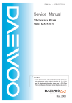
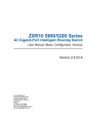
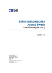
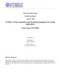
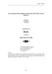
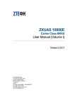
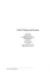
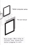
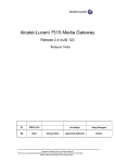
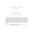
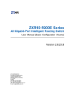
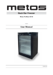
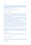
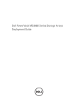
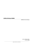
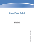
Preface
In this issue of ZTE's "Maintenance Experience", we
continue to pass on various field reports and resolutions that are
gathered by ZTE engineers and technicians around the world.
The content presented in this issue is as below:
● One Special Document
● Ten Maintenance Cases of ZTE's Data Products
Have you examined your service polices and procedures
lately? Are you confident that your people are using all the
tools at their disposal? Are they trained to analyze each
issue in a logical manner that provides for less downtime and
maximum customer service? A close look at the cases reveals
how to isolate suspected faulty or mis-configured equipment,
and how to solve a problem step by step, etc. As success in
commissioning and service is usually a mix of both discovery
and analysis, we consider using this type of approach as an
example of successful troubleshooting investigations.
While corporate leaders maintain and grow plans for
expansion, ZTE employees in all regions carry out with individual
efforts towards internationalization of the company. Momentum
continues to be built, in all levels, from office interns to veteran
engineers, who work together to bring global focus into their
daily work.
If you would like to subscribe to this magazine (electronic
version) or review additional articles and relevant technical
materials concerning ZTE products, please visit the technical
support website of ZTE Corporation (http://ensupport.zte.com.
cn).
If you have any ideas and suggestions or want to offer your
contributions, you can contact us at any time via the following
email: [email protected].
Thank you for making ZTE a part of your telecom experience!
Maintenance Experience
Bimonthly for Data Products
No.29 Issue 176,August 2009
Maintenance Experience
Editorial Committee
Director: Qiu Weizhao
Deputy Director: Chen Jianzhou
Editors:
Jiang Guobing, Zhang Shoukui, Wu Feng,
Yuan Yufeng, Tang Hongxuan, Li Gangyi,
Song Jianbo, Tian Jinhua, Wang Zhaozheng,
Liu Wenjun, Wang Yapping, Lei Kun, Ge Jun,
Wang Tiancheng, Yu Qing, Zhang Jiebin,
Fang Xi
Technical Senior Editor:
Hu Jia, Bai Jianwen
Executive Editor:
Zhang Fan
Maintenance Experience
Newsroom
Address: ZTE Plaza, Keji Road South, Hi-Tech
Industrial Park, Nanshan District,
Shenzhen, P.R.China
Postal code: 518057
Maintenance Experience Editorial Committee
ZTE Corporation
August, 2009
Contact: Ning Jiating
Email: [email protected]
Tel: +86-755-26771195
Fax: +86-755-26772236
Document support mail box: [email protected]
Technical support website: http://ensupport.zte.
com.cn
Contents
802.1x Protocol Configuration.............................................................................................................2
Private Protocol Configuration of ZTE 802.1x Client in 2826S............................................................9
802.1x Authentication Disconnection Malfunction............................................................................. 11
ZXR10 2826S Failed to Pass Radius Authentication........................................................................13
User Fails to Obtain IP Address by DHCP Relay..............................................................................14
SSH Local Authentication Usage......................................................................................................15
MPLS VPN Inter-access Malfunction................................................................................................17
ZXUAS WLAN+WEB Authentication Failure.....................................................................................20
UAS10600 and PORTAL Interconnection Failure..............................................................................22
VRRP Packet Loss............................................................................................................................26
T64E Version Upgrading Malfunction................................................................................................27
August 2009
Issue 176
802.1x Protocol Configuration
⊙ Wang Huali / ZTE Corporation
Key word: 802.1x
1 802.1x Overview
network and use network service.
IEEE 802.1x is called Port-based
With the rapid development and large scale
Network Access Control Protocol.
application of LAN, the requirements for safety
Port-based access control provides
authentication are under investigation. The heat
authentication and authorization for users
topic in the industries is how to make use of the
or devices to access to LAN by means of
simple and cheap characteristics of LAN to provide
IEEE 802.X. 802.1x authentication is able
authentication for user or devices. Therefore, IEEE
to provide point-to-point user identification
802.1X emerge as the times require.
in multi-point access environment.
In LAN defined by IEEE 802.x, as
long as a physical interface exists, the
2 802.1x Protocol Architecture
802.1x protocol architecture is shown in Figure 1.
unauthorized network device can access
to LAN, or unauthorized user can access
to network through a device connected
to LAN. For example, an office network
can access to public network. In such a
network, the network owner does not allow
unauthorized users or devices to access
Maintenance Experience
Figure 1. 802.1x Architecture
www.zte.com.cn
802.1 x architecture consists of the following
main parts:
VLAN+physical port and so on.
In physical port-based control mode,
● Supplicant System
each physical port consists of two logical
● Authenticator System
ports, controlled and uncontrolled port.
● Authentication Server System
Uncontrolled port transmits authentication
Figure 1 shows the relation and communication
protocol packets, and controlled port
among three main parts. Client software is
transmits service packets.
installed on Supplicant system. User enters
Another control mode is based on the
802.1x authentication process by using client
VLAN ID of the user device. VLAN ID of
software. To support port-based access control,
user device is considered to be a port.
supplicant system has to support EAPoverLAN
Each user device has two logical ports,
(EAPoL). Authenticator system is a network device
controlled and uncontrolled port.
supporting 802.1x.
3 Port State and Control Mode
The ports of authenticator system are
divided into two logical port, controlled port and
4 802.1x Authentication
Process
802.1x authentication process is shown
in Figure 2.
uncontrolled port.
Uncontrolled port is used to transmit
authentication protocol packets no matter it is
authenticated or unauthenticated.
Controlled port is used to transmit service
packets. If user passes authentication, the
controlled port enters authenticated state and
it can transmit service packets. If user fails to
pass authentication, the uncontrolled port enters
unauthenticated state and it can not transmit
service packets.
Controlled port is disabled in the state of
unauthenticated. In this time, switching function
of switch is disabled. That is to say, switch can
Figure 2. 802.1x Authentication Process
not exchange data by searching destination MAC
addresses. Therefore, service packets of users can
not be transmitted.
The authentication procedure is
described as follows:
After user passes the authentication,
1. 802.1X supplicant system sends
the controlled port is disabled and it enters
EAPOL-Start packet to access device for
authenticated state. In this time, switching function
starting 802.1X authentication access.
is enabled in switch. Switch is able to exchange
2. Access device sends EAP-Request/
data with the conventional method. User service
Identity response packet to supplicant
packets can be transmitted well.
system for requesting the legal identifier,
There are many methods to control port. The
port can be a logical port, physical port, VLAN or
such as, user name and password.
3. Supplicant system responds to
Data Products
August 2009
Issue 176
EAP-Response/Identity packet including
11. The allocated address information is
username and password to access the
responded to authentication system. Authentication
device. The authentication packet is
system records user information, such as MAC
transferred through the uncontrolled port
address, IP address and so on, and creates
because the supplicant system has not
dynamic ACL list to control user authority.
passed the authentication.
4. Access device encrypts EAPResponse/Identity packet into Radius
netflow.
13. Authentication server system replies access
Access-Request packet to authentication
device for accounting. At this step, use connects
server system for authentication.
the Internet.
5. Authentication server system
14. To leave the network, the user will pass
sends RADUIS Access-Challenge packet
through software on supplicant system. When
including EAP-Request/MD5-Challenge to
receiving the leaving request, the access device
supplicant system through access device.
will notify authentication server system to stop
6. Access device sends EAP-Request/
accounting and delete user information. The
MD5-Challenge to supplicant system for
controlled logical port will be disabled. Users need
requesting authentication.
to authenticate if they want to connecting network.
7. After EAP-Request/MD5-Challenge
15. Access device ensures the activity of link
packet is received by supplicant system,
through periodic detection. If computer corruption
Challenged-Password which is calculated
occurs, access device will consider the user has
from password and Challenge by MD5
left the computer automatically after launching
arithmetic is responded to access device
detection many times. Access device will send the
through EAP-Response/MD5-Challenge.
request to stop accounting to authentication server
8. Access device sends Challenge,
Radius server for authentication.
9. RADIUS server implements MD5
arithmetic according to user information for
judging whether user is legal or not, and
system.
5 Configuring 802.1x
5.1 Configuration Idea and Steps
The following aspects need to be considered in
802.1x configuration,
then responds authentication result packet
● Enable authentication
to access device. If the authentication is
● Create and delete authentication rule
successful, then a packet with negotiation
parameters and the related service
● Create and delete local authentication user (if
local authentication is required)
attribution is sent back for authorization.
● Configure authentication rule
If the authentication is failed, then the
● Configure radius server
authentication procedure ends.
● Configure 802.1x parameters
10. If the authentication is successful,
Configuration steps are shown below.
the controlled port is enabled. User
1. Enable authentication, enter NAS
obtains the allocated IP address from
configuration mode from global configuration mode.
DHCP Server through the standard DHCP
protocol (it can be DHCP Relay).
Maintenance Experience
to authentication server system when it detects
Access-Request packet and sends Radius
Challenged password and user name to
12. Access device will send accounting request
2. Create or delete authentication rule.
Authentication rule can be either VLAN+port based
www.zte.com.cn
or specified VLAN port-based.
3. Create or delete local authentication user.
When the mode is local authentication, configure
user information of local authentication, including
user name, password, VLAN ID, MAC address and
so on.
4. Configure authentication rule and
parameters, including,
● The parameter control, it has two options,
dot1x and dot1x-relay
● Access authorization mode (authorization):
auto, force-unauthorized and force-authorized
● Access authentication mode (authentication):
RADIUS, local
● Authentication protocol in RADIUS server
(protocol): pap and chap
● The period for waiting response from
client (supplicant-timeout).
● The period for waiting response from
authentication server (server-timeout).
● The retransmission times for waiting
authentication server response (maxrequest).
For detail configuration commands,
● User name is used with ISP name
please refer to user manual.
● The default user name
5.2 802.1x Configuration Example
One:dot1x-relay Local
Authentication
● Authentication and accounting RADIUS
server (Radius-Server)
● On-line detection of access user (keepalive):
enable, disable
As shown in Figure 3, PC1 and PC2
belong to VLAN 100. There are two G
● On-line detection period (keepalive-period)
series switches, A and B. Switch A acts as
● Access accounting (accounting): enable,
dot1x server, and switch B acts as dot1x-
disable
● Multi-user access (multiple-hosts)
relay. Dot1x server and dot1x-relay are
interconnected through Trunk.
● The maximum number of users (max-hosts)
5. Configure RADIUS server, authentication
and accounting parameters, RADIUS server, and
retransmission times.
6. Configure 802.1x parameters.
● Re-authentication: enable, disable. 802.1x
protocol has a re-authentication mechanism. The
mechanism can be enabled or disabled. If it is
enabled, user needs to restart its authentication.
● Re-authentication-period: Configure the time
interval for performing re-authentication.
● Quiet-period: It is used to control a user not
Figure 3. Dot1x-relay Local Authentication
Configuration requirements:
● The VLAN 100-based rule is
configured as local authentication in dot1x
server.
to restart its authentication in a certain time if the
● Configure multiple-host.
authentication is failed.
● keepalive-period is 20 seconds.
● The time interval for retransmitting client ID
(tx-period).
● Local user name is test and
password is test.
Data Products
August 2009
Issue 176
1. Configure dot1x server in switch A,
ZXR10_A(config)#nas
ZXR10_A(config-nas)#create aaa 10 vlan 100
/* This creates vlan 100-based authentication rule.*/
ZXR10_A(config-nas)#aaa 10 control dot1x enable
/*This configures the parameter control is dot1x.*/
ZXR10_A(config-nas)#aaa 10 authentication local
/* This configures access authorization mode is local.*/
ZXR10_A(config-nas)#aaa 10 multiple-hosts enable
/*This configures multiple-hosts.*/
ZXR10_A(config-nas)#aaa 10 keepalive enable period 20
/*This configures keepalive period is 20 seconds.*/
2. Configure local user in switch A,
ZXR10_A(config-nas)#create localuser 1 name test password test
/*This creates user name and password of local authentication user.*/
ZXR10_A(config-nas)#localuser 1 vlan 100
/*This configures local authentication user VLAN is VLAN 100.*/
3. Configure dot1x-relay in switch B,
ZXR10_B(config)#nas
ZXR10_B(config-nas)#create aaa 12 vlan 100
ZXR10_B(config-nas)#aaa 12 control dot1x-relay enable
/*This configures This configures the parameter control is dot1x-relay.*/
5.3 802.1x Configuration Example
Two: Radius Authentication
with Accounting Function
As shown in Figure 4, PC1 and PC2
belong to VLAN 100. Radius Server
belongs to VLAN 200. The IP address
of Radius server is 10.40.92.2, 24 bits
sub-network mask, gateway address is
10.40.92.1.
Figure 4. Radius Authentication with
Accounting Function
1. Configure authentication rule in switch A.
ZXR10_A(config)#nas
ZXR10_A(config-nas)#create aaa 2 vlan 100
ZXR10_A(config-nas)#aaa 2 control dot1x enable
ZXR10_A(config-nas)#aaa 2 authentication radius
/* This configures the access authorization mode is RADIUS server authentication.*/
ZXR10_A(config-nas)#aaa 2 accounting enable
/*This enables accounting function.*/
ZXR10_A(config-nas)#aaa 2 multiple-hosts enable
Maintenance Experience
www.zte.com.cn
ZXR10_A(config-nas)#aaa 2 keepalive enable
ZXR10_A(config-nas)#aaa 2 protocol chap
/*This configures to adopt CHAP as authentication protocol in RADIUS server*/
ZXR10_A(config-nas)#aaa 2 radius-server 1
ZXR10_A(config-nas)#aaa 2 fullaccount enable
/* This configures the user name to bring ISP name.*/
ZXR10_A(config-nas)#aaa 2 default-isp 163
/*This configures the default ISP name is 163.*/
2. Configure authentication server in switch A.
ZXR10_A(config)#radius server 1 authen master 10.40.92.2 1812 fang
/*This configures IP address of master authentication server is 10.40.92.2, the port number
is 1812, authentication key is fang.*/
ZXR10_A(config)#radius server 1 account master 10.40.92.2 1813 fang
/* This configures IP address of master accounting server is 10.40.92.2, the port number is
1813, authentication key is fang.*/
ZXR10_A(config)#interface vlan 200
ZXR10_A(config)#ip add 10.40.92.1 255.255.255.0
3. Configure authentication rule in switch B.
ZXR10_A(config)#radius server 1 authen master 10.40.92.2 1812 fang
/*This configures IP address of master authentication server is 10.40.92.2, the port number is
1812, authentication key is fang.*/
ZXR10_A(config)#radius server 1 account master 10.40.92.2 1813 fang
/*This configures IP address of master accounting server is 10.40.92.2, the port number is
1813, authentication key is fang.*/
ZXR10_A(config)#interface vlan 200
ZXR10_A(config)#ip add 10.40.92.1 255.255.255.0
5.4 802.1x Configuration Example Three:
Configuration of Active/Standby
Radius Server in Low-end Switch
As shown in Figure 5, T160G connects to two
RADIUS authentication servers. One is active,
and the other is standby. The IP address of
active RADIUS server is 172.16.1.166, and that
of standby RADIUS server is 172.16.1.110. The
gateway of L2 switch is configured in T160G. L2
switch can access to user directly, or connects to a
L2 switch. The management IP address of 2826s
is 172.16.254.12, 25 bits sub-network mask. No.24
port connects to 2852s, port 1~23 connect to
users.
Figure 5. Configure Active/Standby Radius
Server in Low-end Switch
Data Products
August 2009
Issue 176
1. Configure IP address in 2826s for network management.
zte(cfg)#config router
zte(cfg-router)#set ipport 0 ipaddress 172.16.254.12 255.255.255.128
zte(cfg-router)#set ipport 0 vlan 4093
zte(cfg-router)#set ipport 0 enable
zte(cfg-router)#iproute 0.0.0.0 0.0.0.0 172.16.254.1
2. To realize 802.1x function, security attribute has to be enabled in port.
zte(cfg)#set port 1-23 security enable
3. Configure Radius ISP.
zte(cfg)#conf nas
zte(cfg-nas)#radius isp daxue enable
/*This adds a ISP called daxue.*/
zte(cfg-nas)#radius isp daxue defaultisp enable
/*This specifies the domain as default domain.*/
zte(cfg-nas)#radius isp daxue sharedsecret ocean
/* This configures shared key of domain as ocean.*/
zte(cfg-nas)#radius isp daxue add accounting 172.16.1.166 1813
/*This adds accounting server whose IP address is 172.16.1.166 in domain, the port
number is 1813.*/
zte(cfg-nas)#radius isp daxue add authentication 172.16.1.166 1812
/*This adds authentication server whose IP address is 172.16.1.166 in domain, the port
number is 1812.*/
zte(cfg-nas)#radius isp daxue client 172.16.254.12
/*This configures IP address of Radius client as 172.16.254.12.*/
zte(cfg-nas)#radius isp daxue add accounting 172.16.1.110 1813
/*This configures standby accounting server.*/
zte(cfg-nas)#radius isp daxue add authentication 172.16.1.110 1812
/*This configures standby authentication server.*/
4. Configure aaa access control.
zte(cfg-nas)#aaa-control port 1-23 dot1x enable
/*This enables 802.1x authentication access in port 1~23.*/
zte(cfg-nas)#aaa-control port 1-23 protocol chap
zte(cfg-nas)#aaa-control port 1-23 keepalive client-ip enable
zte(cfg-nas)#aaa-control port 1-23 keepalive enable
zte(cfg-nas)#aaa-control port 1-23 keepalive period 180
zte(cfg-nas)#aaa-control port 1-23 accounting enable
zte(cfg-nas)#aaa-control port 1-23 multiple-hosts enable
zte(cfg-nas)#dot1x quiet-period 0
/* This configures the quiet period is 0. User can re-authenticate without limitation.*/
Maintenance Experience
www.zte.com.cn
Private Protocol Configuration of ZTE
802.1x Client in 2826S
⊙ Wang Baoyuan / ZTE Corporation
Key words: 2826s, 802.1x, private protocol, authentication timeout
Malfunction Situation
As shown in Figure 1, 802.1x authentication
client prompted that the authentication is
overtime.
function was enabled in 2826S. User PC accessed
to authentication switch 2826S through UT switch
and then it was authenticated by AAA server. ZTE
802.1x client was installed in user PC. The user
failed to pass the authentication by dialing. The
Figure 1. User PC Authentication Timeout
Malfunction Analysis
Engineer enabled DEBUG function of AAA and Radius in 2826S to view the information, as
shown below.
zte(cfg)#host DEBUG
Important notice!
------------------------------------The debug mode is used to collect some information which may be useful for
analyzing problems.
Unauthorized use of those commands is prohibed .
Those commands are not under tested.
It is recommended to restart the S300 after run debug commands.
------------------------------------Copyright 2002 ZTE.
zte(debug)#debug nas aaa en
zte(debug)#debug nas radius en
Data Products
August 2009
Issue 176
There was no information in the output result, which indicated that 2826S could not receive
802.1x authentication packets from user PC. Therefore, AAA server would not respond and user
could not pass the authentication.
User PC used 802.1x client. 802.1x authentication packets were sent if the software ran
properly. Therefore, engineer estimated that authentication packets were lost by UT switch.
Engineer captured packets in egress and ingress of UT switch. The result showed that the packets
sent by PC arrived in UT switch ingress but 802.1x authentication packets could not be captured
in egress. UT switch did not support 802.1x packet transparently transmission so that it discarded
802.1x packets as abnormal packets.
Solution
The following command can be corporately used with ZTE 802.1x client to configure private
protocol. The private protocol helps 802.1x packets to pass through the intermediate devices.
zte(cfg)# dot1x add fid <X> mac <XX.XX.XX.XX.XX.XX>
Engineer selected private protocol option in client configuration and configured MAC address.
MAC address has to be consistent with that of authentication switch. After that, the switches
coming from other manufactories will broadcast authentication like unknown unicast packet, and
the authentication packets will be transmitted to authentication switch finally.
However, it is inconvenient for users. Therefore, engineer modified the command as follows,
zte(cfg)# dot1x add fid <VLAN-ID> mac 01.d0.d0.ff.ff.ff
Here, <VLAN-ID> indicates that FID which user VLAN belongs to. 01.d0.d0.ff.ff.ff is the default
ZTE private MAC address, it does not conflict with other manufactories. The configuration of
client can be simplified further. It is enough to select private protocol option. MAC address is not
required to be input.
After private protocol was enabled by engineer, user PC passed the authentication and
accessed to the Internet. ■
10
Maintenance Experience
www.zte.com.cn
802.1x Authentication Disconnection
Malfunction
⊙ Zhang JinTao / ZTE Corporation
Key words: 2626, ZXISAM, AAA, RADIUS, 802.1X, supplicant system, authenticator
system, authentication sever
Malfunction Situation
The gateway of Radius server was
As shown in Figure 1, ZXISAM authentication
configured in T64G. Network management
software was run on PC, 802.1x authentication
IP address was configured by 2626. The
function was enabled in ZXR10 2626. Client
gateway of 2626 was configured in T64G.
passed the authentication in RADIUS server and
User PC passed the authentication by
then obtained IP address by DHCP to access the
ZXISAM and was connected to the Internet
Internet. DHCP server was run on T64G.
properly. However, ZXIASM authentication
frequently failed after user restarted the
PC.
Malfunction Analysis
802.1x protocol was used to perform
user identification in this network. 802.1x
authentication system consists of the
following three parts:
● Supplicant system: It is the PC
running ZXIASM software.
● Authenticator system: ZXR10 2626.
Figure 1. 802.1x Authentication
Disconnection Malfunction
● Authentication server: Radius server.
802.1x is based on port. ZXR10 2626
Data Products
11
August 2009
Issue 176
only permitted authentication packets to
if they pinged the gateway of 2626 by 2626 when
be transmitted before user passed the
the authentication was failed. Engineers used
authentication.
command show arp in T64G to view ARP entry.
The steps for 802.1x authentication are
shown below.
The malfunction reason was clear now. The
authentication request (EAPOL packets) to
disconnection between authenticator system and
authenticator system.
authentication system caused the failure of the
2. Authenticator system forwards
packets) of supplicant system to
authentication server.
user authentication.
Solution
Engineers used the command arp add
3. Authentication server returns
<A.B.C.D> <xx.xx.xx.xx.xx.xx> in T64G to statically
authentication result (EAPOR packet) to
bind ARP entry of 2626. Here, <A.B.C.D> is the
authenticator system.
IP address, and <XX.XX.XX.XX.XX.XX> is the
4. Authenticator system forwards
MAC address. After that, engineers pinged the
authentication result (EAPOL packets)
gateway of 2626 in 2626 again, and they found
received from authentication server to
the connection was recovered and no packet was
supplicant system.
lost. Engineers pinged Radius server and still no
Engineers inspected the devices and
found that the packets were lost heavily
Maintenance Experience
always could not be learnt.
1. Supplicant system sends
the authentication information (EAPOR
12
The result showed that ARP information of 2626
packets were lost. In this time, user could pass the
authentication and accessed to the Internet. ■
www.zte.com.cn
ZXR10 2826S Failed to Pass
Radius Authentication
⊙ Wang TuJian / ZTE Corporation
Key words: 2826S, 802.1X, HUB, transparent transmission 802.1x
Malfunction Situation
As shown in Figure 1, ZXR10 2826S switches A
and B composed the network. 802.1X was enabled
connect to 2826S-A. After that, engineers
found that PC2 was able to pass Radius
authentication.
in 2826S-A. 2826-B acted as HUB for accessing
Thus it could be seen that ZXR10
without any configuration. The users connected to
2826S could not process 802.1x packet
2826-B could not pass Radius authentication.
like a HUB if without any configuration. By
default, 802.1x transparent transmission
function is disabled in ZXR10 2826S. That
is to say, 802.1x protocol packets could
not be transparently transmitted by 2826S.
Therefore, the connected user failed to
pass authentication.
Solution
Engineers enabled 802.1x transparent
transmission function in 2826S-B, and
then the connected user could pass
Radius authentication.
The following command is used to
Figure 1. Network Structure
Malfunction Analysis
enable 802.1x transparent transmission
function.
zte(cfg)# set dot1x-relay enable
Engineers found that the user connected to
2826-S (such as PC1) was able to pass Radius
authentication and accessed to the Internet.
Engineers planned to connect a HUB to
2826S-A for user accessing. However, engineers
found that 2826S-B could not act as HUB without
any configuration and PC2 could not pass the
authentication.
Engineers replaced 2826S-B with a HUB to
Data Products
13
August 2009
Issue 176
User Fails to Obtain IP Address by DHCP
Relay
⊙ Wang Tao / ZTE Corporation
Key words: DHCP, relay, fails to obtain IP address
Malfunction Situation
engineers performed the following tests,
As shown in Figure 1, DHCP server
1. Engineer inspected the routing between
function was configured in Radius server,
T160G and Radius server, and they pinged these
DHCP Relay was configured in T160G.
devices. The devices could be pinged.
However, user PC failed to automatically
obtain IP address in T160G.
2. Engineer enabled debug function in T160G,
and the information is as follows:
The network is composed of:
● VLAN 300 (gei4/7-8) in T160G is
01:57:58 DHCPR:npc 12 rcv dhcp forward
used to connect users. The gateway IP
packet
address of user is 10.1.12.1/24.
01:57:58 DHCPR:can not get valid forward
● VLAN 100 (gei4/3) interconnects with
npc no
RADIUS. The interconnection IP address
01:57:58 DHCPM:vlan300 receive
is 10.10.0.0-10/30.
DHCPDISCOVER[001E.C9E6.6FDC]!
● IP address of Radius server is
10.1.1.3. Routing is accessible between
T160G and RADIUS.
Malfunction Analysis
To find and resolve the problem,
01:57:58 DHCPR:send DHCPDiscover from
10.1.12.1 to 10.1.1.3
3. Engineers inspected Relay configuration of
T160G.
4. Engineers inspected address pool
configuration of DHCP Server. The result showed
the configuration was proper.
5. Engineers inspected relay information of
DHCP Server. They found the fault reason that
DHCP relay address was the interconnection
address between T160G and firewall. The correct
relay address shall be gateway address of users.
Solution
Engineers modified DHCP relay address and
tested again. PC could obtain IP address and
connected to the Internet. The malfunction was
Figure 1. DHCP Relay
14
Maintenance Experience
recovered. ■
www.zte.com.cn
SSH Local Authentication Usage
⊙ Zhu Xuan / ZTE Corporation
Key words: SSH, RADIUS, Local authentication
Configuration Description
username being zte and password being
As shown in Figure 1, WinRadius is installed on
123. Click OK. Figure 2 shows the details.
PC to run Radius Server. Putty is installed to act as
Result: System setting menu appears.
SSH Client.
Figure 1. SSH Radius/Local Authentication
Configuration
Enable SSH in router and configure SSH and
Radius. Install Radius and SSH software in PC.
Note: Local authentication mode is only
handed over when Radius authentication is
invalid.
Configuring Radius Server
1. Open the WinRadius.exe. Select the
Add an Account menu to add an account with the
Figure 2. Radius Server Account Configuration
2. Select the System Setting menu.
Set the NAS password to zxr10 and auth
port to 1812, and then click OK, as shown
in Figure 3.
Data Products
15
August 2009
Issue 176
Figure 3. Radius Server System Configuration
3. Ping the PC in router. The PC can
be pinged.
Configuring Radius and SSH
in Router
1. Configure Radius in router, as
follows:
Figure 4. SSH Client Login Configuration 1
16. Select version 2 from the protocol options
and select the SSH version, as shown in Figure 5.
ZXR10(config)#radius authenticationgroup 1
ZXR10(config-authgrp-1)#server 1
192.168.7.209 key zte
ZXR10(config-authgrp-1)#exit
ZXR10(config)#radius auto-change on
/*After Radius authentication is
overtime, the authentication mode is
handed over local authentication. */
Here, the key is zte. The key has to be
consistent with NAS key.
Radius configuration is finished in
router. Use show run command to view
the configuration.
2. Configure SSH in router, as follows:
ZXR10(config)#ssh server enable
Figure 5. SSH Client Login Configuration 2
17. Click open. The login interface appears,
as shown in Figure 6. Directly enter the user name
and password of Radius Server in the interface.
The login is successful.
ZXR10(config)#ssh server version 2
ZXR10(config)#ssh server
authentication mode radius
ZXR10(config)#ssh server
authentication ispgroup 1
Logining Router from PC
1. Enable Putty.exe at the SSH client.
Enter the IP address of the remote router
192.168.4.42 in hostname. The interface
is shown in Figure 4.
16
Maintenance Experience
Figure 6. SSH Login Interface 1
18. Enter the local user name and password
for login. The login is unsuccessful.
5. Shut down Radius server. Re-enter local
user name and password for login. The login is
successful. ■
www.zte.com.cn
MPLS VPN Inter-access Malfunction
⊙ Qu ZhiHui / ZTE Corporation
Key words: T600, MPLS VPN, mask, ping
Malfunction Description
As shown in Figure 1, MPLS VPN was enabled
in DCN network, Cisco 12410 acted as P device,
ZXR10 T1200 acted as router reflector and ZXR10
T600 acted as PE device and router reflector client.
After the configuration was finished, user found
the following problems:
● PC1 and PC2 could not ping each other
successfully.
● T600-2 could not ping PC1, but T600-1 could
ping PC2.
Figure 1. DCN Network Topology
T600-2#ping vrf jl-dcnbss 192.168.13.2
sending 5,100-byte ICMP echoes to 192.168.13.2,timeout is 2 seconds.
!!!!!
Success rate is 100 percent(5/5),round-trip min/avg/max= 1/2/4.
T600-1#ping vrf jl-dcnbss 192.168.13.18
sending 5,100-byte ICMP echoes to 192.168.13.18,timeout is 2 seconds.
.....
Success rate is 0 percent(0/5).
● T600-3 could ping PC1 and PC2.
T600-2#ping vrf jl-dcnbss 192.168.13.17 source 192.168.13.1
sending 5,100-byte ICMP echoes to 192.168.13.17,timeout is 2 seconds.
!!!!!
Success rate is 100 percent(5/5),round-trip min/avg/max= 1/1/2.
Data Products
17
August 2009
Issue 176
Malfunction Analysis
To resolve the problem, engineers performed the following steps,
1. Engineers checked whether the problems existed.
2. Engineers pinged PC1 by T600-1, and they pinged PC2 by T600-2 to make sure that the
directly-connected network segment can be pinged.
T600-2#ping vrf jl-dcnbss 192.168.13.2
sending 5,100-byte ICMP echoes to 192.168.13.2,timeout is 2 seconds.
!!!!!
T600-1#ping vrf jl-dcnbss 192.168.13.18
sending 5,100-byte ICMP echoes to 192.168.13.18,timeout is 2 seconds.
!!!!!
Success rate is 100 percent(5/5),round-trip min/avg/max= 1/1/1.
3. Engineers pinged gateway address of PC1 by T600-1, and they pinged gateway address of
PC2 by T600-2 to confirm whether the routing is failed.
T600-2#ping vrf jl-dcnbss 192.168.13.17 source 192.168.13.1
sending 5,100-byte ICMP echoes to 192.168.13.17,timeout is 2 seconds.
!!!!!
Success rate is 100 percent(5/5),round-trip min/avg/max= 1/1/2.
4. Engineers pinged PC2 address by T600-1, and they pinged PC1 address by T600-2 to
make sure that PC gateway and mask are correct.
T600-1#ping vrf jl-dcnbss 192.168.13.2
sending 5,100-byte ICMP echoes to 192.168.13.2,timeout is 2 seconds.
!!!!!
Success rate is 100 percent(5/5),round-trip min/avg/max= 1/2/4.
T600-2#ping vrf jl-dcnbss 192.168.13.18
sending 5,100-byte ICMP echoes to 192.168.13.18,timeout is 2 seconds.
.....
Success rate is 0 percent(0/5).
5. Engineers found that PC 2 gateway and mask configuration were correct, but the
malfunction occurred due to PC1 gateway, mask configuration or other factors.
6. Engineers performed the following test in T600-3 to confirm whether the configuration of
PC1 was correct. The test result showed that the configuration was correct.
T600-3#ping vrf jl-dcnbss 192.168.13.18
sending 5,100-byte ICMP echoes to 192.168.13.18,timeout is 2 seconds.
!!!!!
Success rate is 100 percent(5/5),round-trip min/avg/max= 12/12/13.
18
Maintenance Experience
www.zte.com.cn
7. Engineers doubted that 192.168.13.18 was conflicted in the network. However, the tracing
result showed that the address was not conflicted.
T600-1#trace vrf jl-dcnbss 192.168.13.18
tracing the route to 192.168.13.18
1 *.110 MPLS : Label 6282/5988 Exp 0 20 ms 17 ms 17 ms
2 *.113 MPLS : Label 1648/5988 Exp 0 16 ms 16 ms 16 ms
3 *.102 MPLS : Label 24/5988 Exp 0 18 ms 18 ms 18 ms
4 67.5.9.97 17 ms 16 ms 16 ms
5 192.168.13.18 14 ms 14 ms 14 ms
[finished]
8. Engineers used gateway address of PC2 as source IP address to ping PC1 in T600-2,
and PC1 could not be pinged.
T600-2#ping vrf jl-dcnbss 192.168.13.18 source 192.168.13.1
sending 5,100-byte ICMP echoes to 192.168.13.18,timeout is 2 seconds.
.....
Success rate is 0 percent(0/5).
Solution
The mask configuration of PC1 was incorrect so that PC1 recognized that it and PC2 belonged
to the same network segment. Therefore, after PC1 received packets from PC2, it would send
ARP request to ask PC2 MAC address but not send ping respond packet to T600-1. Additionally,
engineer could not ping PC1 in T600-2 because the ping packet sent by T600-2’s MAC source
address was 192.168.13.1. ■
Data Products
19
August 2009
Issue 176
ZXUAS WLAN+WEB Authentication
Failure
⊙ Wang Yufeng / ZTE Corporation
Key words: DHCP, Portal, firewall, BRAS
Malfunction Description
Malfunction Analysis
As shown in Figure 1, PC accessed
1. Engineers captured the packets in BRAS
to AP by wireless. The following two
according to the two prompts. The result showed
functions were realized at the same time.
that Portal did not send Challenge packets to
● PC was able to connect to UAS
10600 by PPPoE dialing and then obtained
IP address for accessing the Internet.
BRAS.
The malfunction phenomenon showed that
the tunnel between BRAS and Portal had not
● PC was able to obtain IP address
been established. Therefore, the authentication
by DHCP; UAS 10600 could act as DHCP
process would not be performed in fact. Such a
server to assign IP addresses to user.
phenomenon also showed that packet interaction
was not performed between BRAS and Portal.
Without packet interaction, the BRAS and Portal
packets would not match.
2. Engineers discussed with the staffs from
Portal manufactory and confirmed that Portal
server had sent challenge packets to BRAS.
However, engineers captured packets in Portal
Figure 1. WLAN+DHCP+WEB Authentication
Topology
When user entered any website in
IE browser, such as www.zte.com.cn,
an authentication interface appeared.
However, when user entered user name
and password for web authentication, a
prompt of “authentication failure, for some
reasons, code 13000001, information:
server is busy, please try it later” or
“error information: 11001000, SDX error”
appeared.
20
Maintenance Experience
server, and the result showed that there was no
BRAS reply packets. The reason was that BRAS
did not receive Challenge packets from Portal
server. Therefore, engineers considered that the
Challenge packets sent from Portal were blocked
by a device in network. Here, only firewall had such
ability to block packets.
3. Engineers discussed with the staff who was
responsible for firewall, and the staff confirmed that
firewall permits the communication of BRAS and
Portal server.
4. Engineers took PPPoE dialing, to
www.zte.com.cn
● confirm whether the data configuration was correct.
● confirm whether the account information was correct.
● confirm whether the packets sent from BRAS could pass firewall.
5. Engineer used debug radius user command in BRAS. However, the No.691 error always
appeared when engineers dialed up. Engineers discussed with the staff from operator to confirm
the account information. The result showed that the password of test account was changed into
12345678. Engineers used the new password for dialing, and the dialing was successful. BRAS
packets could pass firewall finally.
6. Engineers opened IP for WEB authentication. However, the same error information still
appeared. BRAS configuration was correct, and the related configuration was as shown below.
special-acl 1
permit 218.77.177.33
/*WEB server address.*/
permit 202.100.192.68
/* DNS server address*/
interface vbui111
special-acl 1
web authentication subscriber web force
/*web force indicates that authentication and force-web are enabled.*/
web server 218.77.177.33 port 1814 key gsta
/* This specifies the address of force-web, that is address of web/portal server*/
url http://218.77.177.33
7. Engineers contacted the staff from Portal manufactory again. The staff found that challenge
packets had been sent to BRAS by Portal server, but there were no BRAS reply packets. BRAS
nas-ip-address and user IP addresses had been added into Portal server. At this time, engineers
could not find any user information or Challenge packets even if they captured packets or used
debug radius user command in BRAS.
8. Engineers contacted the staff from operator to check the policy information performed by
firewall for Portal server. Finally, operator staff found that he configured an incorrect Portal server
address.
Solution
Engineers reconfigured firewall, and then they opened IE to perform WEB authentication. The
authentication was successful. Engineers captured packets from Portal server, and the interaction
packets of Portal and BRAS server could be viewed. In Radius server, the packets about passing
authentication could be viewed. In BRAS server, the code=1, code=2, code=4 and code=5 packets
could be viewed too.
Engineers captured packets in BRAS uplink interface. The captured packets showed three
relative UDP packets, as shown in Figure 2.
Data Products
21
August 2009
Issue 176
Figure 2. Interaction Packets of BRAS and Portal Server
These three UDP packets were: Challenge packets sent from Portal server to BRAS, the reply
packets sent from BRAS to Portal server and authentication request packet sent from Portal server
to BRAS. These three UDP packets indicated that the correct tunnel had been established between
Portal server and BRAS. Engineer could inspect whether the format of Portal packets matched BRAS
requirement. The other packets were authentication request packets sent from BRAS to Radius server.
Summary
Engineers have to master the related technologies and know how to resolve problem at each step,
and the communication between engineers and operator staff is very important. ■
UAS10600 and PORTAL Interconnection
Failure
⊙ Liu Peng / ZTE Corporation
Key words: Portal Server, WLAN, HTTPS, NAS-port-type
Malfunction Description
According to the conventional authentication
process, user obtained IP addresses automatically
by DHCP. When users opened any webpage, the
authentication web appeared by force. Users had
to enter the user name and password. After the
authentication was passed, user could access to
Internet.
The network topology of this case is shown in
Figure 1. Network Topology
22
Maintenance Experience
Figure 1.
www.zte.com.cn
The following malfunctions appeared in
practical:
Malfunction phenomenon 1: When users
accessed to L2 switch to obtain IP address, the
force-web did not appear after users entered any
website in the browser.
Malfunction phenomenon 2: When users
entered their user name and password
in authentication webpage, No.15 alarm
“communication with Portal Server is failed”
appeared.
In interconnection test, engineers connected
user to L2 switch without DSLAM and AP. During
this time, the configuration of BRAS is shown
below.
http-param user userip
$
ip pool 16 wlan-1 *.244.2 *.245.254 dhcpslot 1
interface gei_1/2.12 bras
dot1Q 4001
access-type Ethernet
encapsulation dot1q multi
bind multi vbui vbui5 authentication pap
maximum 8000
ppp idle interval 300 traffic-limit 0
ppp keepalive timer 60 count 10
sal 2
ip dhcp enable
sal 2
ip dhcp server dns *.44.150 *.24.68
default domain wlan.hb.*.com
permit domain wlan.hb.*.com
bras
deny any
web server listening-port 2000
node-ip *.61.71
domain 5
special-acl 1
accounting-group 1
permit *.0.130
accounting-type radius
permit *.44.150
authentication-group 1
permit *.24.68
authentication-type radius
max-subscriber 32000
interface vbui5
ppp web-force timer 5 count 0
ip address *.244.1 255.255.254.0
alias wlan.hb.*.com
ip dhcp mode server
subscriber-template
ip dhcp server gateway *.244.1
ip address vrf
special-acl 1
ip proxy-arp none
dhcp idle period 300 traffic 0
dns primary *.44.150
dns secondary *.24.68
dhcp trust-option82
dhcp option60
web authentication subscriber web force
web server 192.168.0.130 port 1814
url http://192.168.0.130
http-param uas uas uas
Analysis and Solution for
Malfunction 1
Malfunction 1 is usually caused by
incorrect configuration of special acl.
However, engineers found that special acl
was configured correctly already. Here, the
IP addresses of Portal server and DNS were
permitted, and engineers could ping the IP
addresses of Portal server and DNS server in
PC.
Data Products
23
August 2009
Issue 176
Engineers checked the parameters of monitoring port, Portal server and port with Portal server
staff again. The result showed that the configurations were correct.
After discussing with Portal Server staffs, engineers found that HTTPS were used by Portal
Server Web-force. HTTPS is Hypertext Transfer Protocol over Secure Socket Layer, which
indicates SSL layer is added into HTTP. SSL is a technology of data encryption, which is widely
used in identifier authentication and encrypted data transmission between Web browser and
server.
If a website is based on HTTPS, it can not be accessed by entering “http://x.x.x.x”. The
differences between HTTP and HTTPS caused malfunction 1.
Engineers modified the force-web to url https://192.168.0.130 in Web server. After that, the
authentication webpage would appear after user entered any website or IP address in IE browser.
Analysis and Solution for Malfunction 2
According to the error information appeared in malfunction 2, engineers doubted that the
communication between BRAS and Portal server was failed. Therefore, engineers used debug
portal command in BRAS. The output for user launching authentication is shown below.
3:10: 5 1/12/2009 Portal: Rx packet: SubIP *.244.3 VpnID 0
3:10: 5 1/12/2009 Portal: Tx packet: SubIP *.244.3 VpnID 0
3:10: 5 1/12/2009 Portal: EnableWebForce: SubIP *.244.3 VpnID 0 enable 0
3:10: 8 1/12/2009 Portal: Rx packet: SubIP *.244.3 VpnID 0
3:10: 8 1/12/2009 Portal: Tx packet: SubIP *.244.3 VpnID 0
3:10: 8 1/12/2009 Portal: EnableWebForce: SubIP *.244.3 VpnID 0 enable 0
3:10:15 1/12/2009 Portal: EnableWebForce: SubIP *.244.3 VpnID 0 enable 0
3:10:18 1/12/2009 Portal: EnableWebForce: SubIP *.244.3 VpnID 0 enable 0
3:10:21 1/12/2009 Portal: Rx packet: Req_Auth, vrf 0, UserIp *.244.3, ErrCode 0, Auth Pap
3:10:21 1/12/2009 Portal: IpSvr Auth Req: vrf 0, UserIp *.244.3, name 9900096_sy@wlan.
hb.*.com
3:10:21 1/12/2009 Portal: IpSvr Auth Complete: vrf 0, UserIp *.244.3
3:10:21 1/12/2009 Portal: Tx packet: Ack_Auth, vrf 0, UserIp *.244.3, ErrCode Reject
3:10:23 1/12/2009 Portal: Rx packet: SubIP *.244.3 VpnID 0
3:10:23 1/12/2009 Portal: Tx packet: SubIP *.244.3 VpnID 0
3:10:23 1/12/2009 Portal:
EnableWebForce: SubIP *.244.3 VpnID 0 enable 0
……
The output showed that the correct user name and password were extracted by BRAS.
However, the Ack_Auth packet showed that the ErrCode packet was Reject. At this time,
engineers could not view the authentication information sent from user when they used debug
radius command. Therefore, the user authentication information could not be compared with
PPPoE dialing user authentication information.
Engineers doubted that the account had problem because the account was sent to Radius
server for authentication as [email protected].*.com, but the test account was a normal
24
Maintenance Experience
www.zte.com.cn
PPPoE dialing account. When PPPoE dialing was
to perform different accounting modes
performed, the user name used in Radius server
according to the access modes rather than
was [email protected]. It was necessary to
domain names.
confirm with Radius server about the account
Obviously, distinguishing accounting
information and authority and whether permits
modes by different domain names tends to
WLAN domain name to access.
cause the accounting confusion because
These two domain names were valid, but an
an accounting user name can bring many
attribute was incorrect, it should be 19 not 16.
domain names and the domain names are
Whose attribute is 16 in user account information?
legal. Therefore, user is possible to use
Engineers searched Radius attribute table, and
they found the attribute of NAS-PORT-TYPE was
WLAN domain name for dialing up, and the
incorrect accounting standard will be used.
16 if the access mode was XDSL. However, when
Distinguishing accounting modes
access mode was WIRELESS_IEEE802_11, the
by combining NAS-PORT-TYPE with
attribute was 19. The configuration of access type
user account is more reasonable and
in BRAS sub-interface influenced this attribute. In
exactable. Therefore, engineers need to
malfunction 2, PC was connected to switch without
configure different access type for WLAN
AP, therefore, the access type of BRAS sub-
user in BRAS.
interface should be Ethernet.
3. When connecting to Portal server
Engineers modified the attribute to access-
or Radius server, debug function can
type WIRELESS_IEEE802_11. After that, user
be used in BRAS device for diagnosis,
entered user name and password, and then they
but sometimes it can not take effect. At
could access to the Internet. Engineers connected
this time, it is difficult to capture packets
AP to BRAS by ADSL, and the PC was connected
in BRAS uplink interface. Therefore,
to AP by wireless, the authentication could also be
engineers can ask for help from server
passed.
side. The malfunction can be located fast
Summary
by capturing packets in server side.
4. When user entered user name
1. The force-web can not appear for WLAN
and password in force-web webpage for
users because of the incorrect special acl
authentication, and if the account was
configuration. However, the malfunction 2 was
abnormal, the alarm information was
caused by HTTPS. Therefore, engineers need to
different with that of PPPoE dialing user.
communicate with Portal server staff in detail when
For example, when user authentication
configuring parameters, including IP address and
is failed because of incorrect NAS-PORT-
port of Portal server, monitoring port and so on.
TYPE attribute, Asiainfor Portal server
Engineers need to check which kind of protocols is
will prompt No.15 alarm information “the
used for authentication webpage, HTTPS or HTTP.
communication with Portal server is failed”.
2. The future developing trend is that an
If the user name or password is incorrect,
account can be used for different application. When
No.10 alarm information “access data
user uses dialing up for accessing the Internet, the
failure” will appear. Such alarm information
account indicates a normal PPPoE user. When
is not clear and visible. Therefore,
user connects to AP by wireless, the account
engineers need to obtain more information
indicates a WLAN user. Radius devices have
from Portal server. ■
Data Products
25
August 2009
Issue 176
VRRP Packet Loss
⊙ Duan Yifei / ZTE Corporation
Key words: VRRP, OSPF, convergence time, preemption, packet loss
Malfunction Description
GER-1,
As shown in Figure 1, there were
some L3 devices in OSPF area. VRRP
GER-1#show run int gei_1/1
was enabled in two GER to provide virtual
Building configuration...
gateway for Radius server. GER-1 acted
interface gei_1/1
as master gateway device, and GER-2
ip address 124.158.127.2 255.255.255.0
acted as slave gateway device.
description as vrrp router for Radius server
vrrp 2 ip 124.158.127.1
vrrp 2 priority 200
vrrp 2 track 1 decrement 150
track 1 interface gei_1/2 line-protocol
GER-1#show vrrp 2
Gei1/1 - Group 2
State is Master
Connection interface is vlan102
Virtual IP address is 124.158.127.1
Virtual MAC address is 0000.5e00.0102
Advertisement interval is 1.000 sec
Preemption is enabled
Figure 1. VRRP Packet Loss
After GER-1 restarted, the packets
sent from Radius server to the devices in
other network segments would be lost in a
short time.
Malfunction Analysis
Engineers viewed the configuration of
26
Maintenance Experience
min delay is 0.000 sec
Priority is 200 (config 200)
Authentication is disabled
Track object 1 decrement 150
Master Router is 124.158.127.2 (local), priority
is 200
Master Advertisement interval is 1.000 sec
Master Down interval is 3.218 sec
www.zte.com.cn
The configuration of GER-2 is omitted.
GER-1(config)# interface gei_1/1
From the above information, engineers found
GER-1(config-if)# vrrp 2 preempt delay 100
that system adopted VRRP preempt by default
And then, engineers restarted GER-1 and
even if VRRP preempt was not configured in the
tested. The malfunction is resolved and no
interface.
packet was lost.
OSPF convergence needs time to finish. The
Another solution is to cancel VRRP
convergence speed depends on the network size.
preempt. After GER-1 restarted, the master
However, VRRP preempt only needs shorter time
gateway switched to GER-2. If GER-2 is failed,
than OSPF convergence if system runs properly
the master gateway will be switched back to
and the port is UP.
GER-1. Engineers did not know the original
Engineers suspected that the master gateway
network design idea, so they respected and
of GER-1 had switched to GER-1 already after
followed the original design to make GER-1 as
GER-1 restarted, but the convergence of OSPF
master gateway.
route has not been finished yet in GER-1. That
caused the packet loss.
Summary
Solution
convergence speed of dynamic routing
The malfunction occurred because the
Engineers used the following command to
protocol is slower than VRRP preemption.
make VRRP master preemption delay 100 seconds
Therefore, we need to pay attention to detailed
in GER-1 interface,
problems in the future. ■
T64E Version Upgrading Malfunction
⊙ Chen WeiDong / ZTE Corporation
Key words: T64E, version upgrading, FTP, ping, overtime
Malfunction Description
Engineer started T64E, and entered “C” to
To upgrade ZXR10 T64E router, the original
enter boot mode. They modified network
version files needed to be deleted, and the device
management port address, IP address of
needed to be power off. That is to say, network
FTP server, FTP user name and password.
startup is used here for upgrading.
Engineers press “@” to start network
Engineers configured the PC as FTP server,
startup. However, the result showed “ftp
and they tested that FTP worked properly.
file………time out”. No version files could
Data Products
27
August 2009
Issue 176
be extracted. The network startup was
engineers found that T64E would send a ping
unsuccessful.
packet to FTP server when T64E network startup
Engineer adopted the same
starts. If the network was normal, FTP server
configuration to upgrade ZXR10 3928. The
responds a packet to T64E, and then T64E
upgrading was successful.
launched FTP connection.
Malfunction Analysis
Engineers took the following steps to
analyse the problem,
1. At first, engineers inspected whether
FTP server worked properly. They tested
FTP server in PC and the result showed
that FTP server work properly.
2. Engineers inspected whether the
network ran properly. However, 3928
switch could be upgraded successfully.
connected to laptop. After discussing, engineers
found that the malfunction was caused by firewall.
Solution
Engineers shut down the firewall. Two directlyconnected laptops could ping each other and run
FTP application. The upgrading was successful.
Summary
FTP mechanisms of our devices are different.
and then tested whether the two laptops
ZXR10 3928 does not have the process of ping,
could ping each other and could run FTP
and it extracts version file from FTP directly.
application. The result showed that two
However, ZXR10 T64E has a process of ping to
laptops could not ping each other and could
create connection. We need to prepare different
not ran FTP application, either. Therefore,
upgrading methods for the different devices.
was caused by network.
Maintenance Experience
simple for device upgrading that only T64E directly
The engineers interconnected two laptops
engineer confirmed that the malfunction
28
4. However, the network connection was very
How to locate the malfunction? At first,
engineers did not know how to resolve the
3. To know more about the interaction
malfunction but they used capturing tool. The
process of T64E upgrading, engineers
malfunction was easy to be located. We need to
captured the packets during the network
be good at applying our tool and accumulating
startup. By capturing the packets,
experience. ■