1
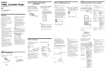
Broadband Cable Networks
User Manual
59300024
30.3.2007
AC8000
Rev.006
1(22)
ACcess Series
User Manual
Teleste Corporation
AC8000
Fibre Node
Broadband Cable Networks
User Manual
59300024
30.3.2007
AC8000
Rev.006
2(22)
Introduction
AC8000 is a dual active output node with high performance characteristics. The
node has been designed to fulfil a variety of needs. It is extremely versatile and
scalable through a wide range of plug-in options. The output amplifier stages
are based on high performance hybrids, what makes the used output level
range especially wide. AC8000 features two high-level distribution outputs. The
second output can be divided into two outputs with a passive output module.
Redundant optical input
The node can be equipped with two optical receivers if redundancy of the
downstream is requested. In the event of fibre break, the platform provides
manual or automatic switchover between alternative fibre paths.
Return path redundancy or segmentation
The upstream channel can also be fully redundant with double transmitter
solution. If more return path segmentation is requested both optical return
transmitters can be fed by separate return signals. Redundant or segmented
upstream operation is selected with the return module.
Redundant powering
Up to two power supplies can be installed in the node. Two field replaceable
housing lids preinstalled with power supply units are available for easy and fast
installation, AC6311 with one power supply and AC6312 with two power
supplies. The field replaceable housing lids are shipped completely including
the connection cable and mounting materials. Equipped with dual power
supplies, the AC8000 platform offers complete system redundancy.
Transponder
AC8000 nodes can be remotely monitored and controlled via the plug-in
transponder unit. Locally the transponder unit can communicate with a lap top
computer or hand-held terminal. With this transponder unit it is possible to
monitor received optical level, transmitter’s laser current, remote voltage, both
power supply output voltages, internal temperature and lid status. Furthermore
the transponder is able to control the backup switching, return path transmitter
as well as return path ingress switches.
Automatic Level Control
Platform features also an automatic microprocessor controlled output level
control (ALC). The ALC function allows monitoring and control of a large
number of parameters in the nodes, optimizing the performance of the platform.
WEEE Notice
This product complies with the relevant clauses of the European
Directive 2002/96/EC on Waste Electrical and Electronic Equipment
(WEEE). The unit must be recycled or discarded according to
applicable local and national regulations.
European Conformity
This equipment conforms to all applicaple regulations and directives
of European Union which concern it and has gone through relevant
conformity assessment procedures.
Broadband Cable Networks
User Manual
59300024
30.3.2007
AC8000
Rev.006
3(22)
Housing
8604043
Fig. 1. AC8000 housing dimensions – top and side view
Installation
The AC8000 can be installed either into a street cabinet or to the outdoor
environment. The node should be installed in a vertical position so that the
external cable connectors are underneath. Secure the housing with three
mounting brackets – see fig. 1 for the positions of mounting brackets as well as
other installation dimensions.
The cover opens with the hinges to the left. The open cover can be removed by
first opening the cover into a 90 degrees angle and the lifting it off the hinges.
Note! Before removing the cover detach carefully the power unit ribbon cable.
Close the lid by tightening the four retaining bolts in a diagonal sequence.
Before closing the lid check that
•
nothing is trapped between the lid and the case
•
all case gaskets are in their correct positions
A sufficient tightening torque is 3 Nm. Ensure that the lid seats evenly on the
rubber gasket. The class of enclosure is IP54.
To ground the node housing connect at least 4 mm2 grounding wire (Cu) from a
proper earth to the grounding point.
User Manual
59300024
30.3.2007
Broadband Cable Networks
AC8000
Rev.006
4(22)
Cable connections
8604050
Grounding point
Fibre input port
Output port 3
Output port 2
Output port 1
Fig. 2. Port locations
The AC8000 fibre node has four dedicated cable connection points: one fibre
input and two/three RF outputs. The amount and function of the actual
connectors varies with the chosen configuration. All coaxial outputs have a
standard PG11 thread and they accept any KDC type adapter or connector. A
suitable length of the coaxial cable inner conductor exposed for the connectors
is approximately 20 mm (Fig. 3).
8604025
Fig. 3. Centre conductor length
User Manual
59300024
30.3.2007
Broadband Cable Networks
AC8000
Rev.006
5(22)
Fibre connections
The node can accept four fibre cables. These cables carry forward path and
return path optical signals. When feeding the optical cable in the node, a
suitable PG11 threaded feed-through adapter type KDO900, is available.
Remove the outer ring of the cable gland, thread the installation fibre filaments
with connectors through the outer ring (Fig. 4 pos. 3), through the sealing insert
(Fig. 4 pos. 2) and finally through the cable gland (Fig. 4 pos. 1).
Mount the cable gland on the housing. The fibre filament length inside the fibre
organiser is adjusted to sufficient measurement before tightening the outer ring.
Use the synthetic locking pins (supplied) to seal up unused holes in the sealing
insert.
8606022
1
2
3
Fig. 4. KDO900 adapter components
Fibre installation
Fibre installation is a critical procedure and it should be done with carefulness.
Incorrect handling of the fibre can result in damage and degraded performance.
Example of routing the fibres can be seen in figure 8.
Cleaning fibre connectors
• For correct optical operation ensure that all optical connectors are cleaned
immediately before mating using a suitable optical connector cleaning kit.
• If a cleaning kit is not available, wipe the end of the connector using pure
isopropyl alcohol (99%) and a lint-free wipe. Dry it with filtered compressed
air. Wait until dry to insert connector into the adapter.
• When fibre optic connectors are unmated, the optical fibre end faces must
be protected from contamination using suitable dust caps. Contamination of
fibre end faces will reduce the performance of the optical fibre and could
ultimately cause failure of the system. Contamination could also damage the
fibre end faces when the connectors are mated.
DANGER! Do not look into the optical connector of the return
transmitter with power applied. Laser light, visible or invisible,
can seriously injure eyes or even cause blindness.
User Manual
59300024
30.3.2007
Broadband Cable Networks
AC8000
Rev.006
6(22)
Powering
The AC6310 is a power supply unit (PSU) to be used in AC8000 lid mechanics.
The node is supplied with 27...65 V AC or 35...90 V DC either via a coaxial
cable or directly at the external input. The external input is located on the power
distribution board at the upper right corner of the amplifier (Fig. 5). External
power can also be fed through the amplifier into the network. Maximum feedthrough current is 10 A per port (15 A total). If powering will be provided through
a dedicated output port, the port must be equipped with a fuse (supplied).
In general only one power supply is needed in the node. However the power
supply unit can work alone or in dual-operation mode if a back-up of the PSU is
needed. In dual powering operation the units are connected in parallel operating
in a passive load sharing mode. The output voltages can be monitored through
the EMT module. The power supply unit also has an auto shut down feature,
which prevents too high input currents if the input voltage should drop below
24 V AC.
The external alarm connector on the power distribution board (Fig. 5) can be
configured to allow input of one external alarm to be monitored with the EMT
module. When external alarm is enabled with the jumper the alarm will be
displayed instead of the PSU2 alarm. Table 1 shows the correct jumper
configurations. The external alarm input is normally connected to a switch. An
alarm is activated when the switch is closed. Whenever external alarm is
enabled verify that the low voltage alarm on PSU2 is set at 23.0 V. Alarm
voltage at a switch closure is typically 18 V…19 V. Refer to the user manual of
“AC6910, AC6940, AC6950 AC PLATFORM TRANSPONDER” for details.
Note! If PSU2 is in use and external alarm is enabled, the only way to confirm
proper operation of the PSU2 is visually check the LED on the PSU circuit
board.
ribbon cable clamp
8604100
ribbon cable header
external alarm connector
alarm jumper
alarm switch
OPEN = no alarm
CLOSED = alarm
Fig. 5. Alarm jumper on the power distribution board
Alarm connected to EMT module
Jumper position
PSU2 alarm (default)
External alarm
Table. 1. Alarm jumper configurations
Broadband Cable Networks
User Manual
59300024
30.3.2007
AC8000
Rev.006
7(22)
Installing the PSU
To gain access to PSU retaining screws, first remove the protective shroud. The
shroud is attached to the lid, to shield the electronics from electromagnetic
interference. Install the PSU board with the four M3x8 mm torx screws. Use the
silicon elastomers between the unit and the heatsink brackets. Make sure to
use the fixing springs in the locations marked with B (Fig. 6).
ac8k_power_b
Fig. 6. AC6310 mounting screws (A), fixing springs (B) and silicon elastomers (C)
Primary and secondary power supplies are physically identical. Their functional
differences are controlled by a jumper. See fig. 7 for locations of the jumper
pins. The jumper must be positioned prior to installation. The primary power
supply unit must be installed into the first place (closest to the hinges). Locate
the 10-pin connectors and attach the supplied ribbon cable.
After PSU installation carefully refit the shroud in the reverse order of removal.
Ensure that all RFI gaskets are in place before the shroud is refitted.
Broadband Cable Networks
User Manual
59300024
30.3.2007
AC8000
Rev.006
8(22)
Before connecting the power make sure that
•
both power supplies are installed in correct positions
•
jumpers is set correctly (Fig. 7)
Connect the power source. The LED on the PSU circuit board indicates that the
unit is powered up and that the DC power supply voltage is present.
8603052
PSU2:
Make sure the
jumper is on the
right-hand location.
PSU1:
Make sure the
jumper is on the
left-hand location.
Fig. 7. Diagram illustrating the AC8000 lid with both PSUs installed.
Broadband Cable Networks
User Manual
59300024
30.3.2007
AC8000
Rev.006
9(22)
Fibre organiser mechanics
The node is equipped with a double sided fibre organiser module. It is meant to
be the installation chassis for the fibre pigtails (Access units) and installation
fibre filaments (external fibre optic cables).
8604076
Fig. 8. AC8000 fibre organiser module
Fitting of the fibres under the retaining tabs is designed to keep the fibres in
place without the use of cable ties. The fibre organizer is equipped with lids to
ensure fibre protection. The lids provide easy and fast re-entry by using plastic
clips.
8605016
Fig. 9. AC8000 fibre organizer
Broadband Cable Networks
User Manual
59300024
30.3.2007
AC8000
Rev.006
10(22)
Carefully wind the fibres around the fibre tray noting the entry points for the
installation fibre filaments (Fig. 10 pos. A) and the fibre pigtail of the optical receiver1 (Fig. 10 pos. C). Each fibre should be connected to its corresponding
adapter (Fig. 10 pos. D). The fibre organiser tray is equipped with slots (Fig. 10
pos. B) for fibres to be routed on either side of the fibre tray. The under side of
the fibre tray is reserved for fibre pigtails of return units and the upper side for
fibre pigtails of forward units.
8604084
Fig. 10. Routing fibres – typical configuration
Where fibres pass the bending point of the fibre organiser module, there must
not be any strain on attachments or excessive slack when it is opened or
closed. Therefore the pigtail of the optical receiver 1 must be routed above all
other fibres – refer to fig. 10.
User Manual
59300024
30.3.2007
Broadband Cable Networks
AC8000
Rev.006
11(22)
Connectors and plug-in slots
58700174
12
11
3
16
4
4
receiver 1
receiver 2
equaliser
attenuator
attenuator
14
15
OMI TP
TX 2
13
6
58700174
OMI TP
TX 1
2
diplex filter
return
module
diplex filter
5
1
receiver 1
receiver 2
transmitter 1
5
transmitter 2
output splitter
17
fuse
fuse
fuse
output 3
10
TP / test
injection
-20 dB
17
output 2
8
TP / test
injection
-20 dB
6
output 1
9
17
Fig. 11. AC8000 plug-in placement,
1)
2)
3)
4)
5)
6)
7)
8)
Optical receiver 1
Optical receiver 2 (backup)
Interstage equaliser
Interstage attenuator(s)
Diplex filter(s)
Output test point(s) /
Test signal injection point(s),
-20 db directional coupler
Output 1
Output module (see table 2)
9)
10)
11)
12)
13)
14)
15)
16)
17)
Output 2
Output 3
Slot for element transponder module
Return module
Slot for optical transmitter 1
Slot for optical transmitter 2
OMI test point for optical transmitter 1
OMI test point for optical transmitter 2
Fuse(s)
7
Broadband Cable Networks
User Manual
59300024
30.3.2007
AC8000
Rev.006
12(22)
Forward path / Optical receivers
The AC6810/20 is a line of fibre optic receiver modules used in the AC8000
node platform. Its performance and the features have been designed for the
fibre to the curb and the fibre to the building (FTTC/ FTTB) applications.
Depending on the optical input power, there are two kinds of modules available
• AC6810 with an optical input power range ranging from -7 dBm to -2 dBm
• AC6820 with an optical input power range ranging from -3 dBm to +2 dBm
It is possible to order the AC8000 platform with only one optical receiver
installed and add a second receiver for backup reasons later. If two optical
receivers are used the primary signal must always be connected to optical
receiver 1 since it is always in use even if the transponder is not installed. The
transponder is able to switch automatically the transmission to the secondary
fibre route in a case of primary route failure.
The output stage uses a GaAs hybrid to improve RF performance over the
entire 47 to 862 MHz passband. A diplex filter is selected during configuration
according to the preferred frequency split.
The second output port, through the use of plug-in output modules, can be set
up for a variety of output configurations. Refer to the ‘Table 2.’ Output modules’.
Output module
Description
AC6112
1/12 dB tap
AC6116
1/16 dB tap
AC6119
1/20 dB tap
AC6120
0 dB output module
AC6124
Two-way splitter
AC6128
2/9 dB tap
Table. 2. Output modules
Gain control
The optical receiver module is delivered without an attenuator plug. If necessary
use an attenuator plug-in to get appropriate RF level. Attenuators of the JDA900
series type ranging from 0 dB to 20 dB in 1 dB steps are available. The
attenuator value depends not only on the optical input level but also on the
optical receiver type and the OMI. Refer to the ‘Table 3. Receiver attenuator
selection guide’.
Broadband Cable Networks
User Manual
59300024
30.3.2007
AC8000
Rev.006
13(22)
Optical input power
Optical input power can be measured with optical power meter or at the receiver
DC test point. The test point DC voltage is directly proportional to optical input
power in mW e.g. 1.0 V corresponds to 1.0 mW average optical power. In case
of a 1310 nm wavelength selection the input power in dBm (W) can be
calculated by the formula
Pin (dBm)=10*log (UTP).
When using 1550 nm transmitters the input power is 0.5 dB lower than this
formula indicates.
Do not connect any voltage to the test point or short circuit it to ground. Use a
voltage meter with an input resistance higher than 100 kohms.
The LED on the receiver’s front panel gives a visual indication of the optical
input power.
LED on AC6810
Condition
Yellow
Optical input power drops below -10.0 dBm
Green
Optical input power is within the nominal range
(-10.0…3.0 dBm)
Red
Optical input power exceeds 3.0 dBm
LED on AC6820
Condition
Yellow
Optical input power drops below -4.5 dBm
Green
Red
Optical input power is within the nominal range
(-4.5…3.0 dBm)
Optical input power exceeds 3.0 dBm
The user can specify all the limits for the LED indication of the optical input
power with the transponder unit. Therefore the above mentioned limits are valid
only if the transponder unit is not installed.
Broadband Cable Networks
User Manual
59300024
30.3.2007
AC8000
Rev.006
14(22)
Element management transponder
Some of the parameters can be controlled and monitored through the
transponder interface. The transponder unit will automatically detect the current
configuration of the Access platform when the user opens the “Configuration”
page. The “Configuration” page displays a graphical view of the current
configuration similar to the actual amplifier/node layout and also generates a set
of viewer pages individual to each active device. It is important to start a
configuration session by selecting first the “Configuration” page since it
is the only way to generate the module specific viewer pages.
Fig. 12. The Optical page
This page is visible in AC8000 platform only. It displays data and settings of the
optical transmitter and receiver modules and controls their connection.
Input selection
These settings provide manual or automatic switchover between two input
channels in case the incoming signal is lost. There are four possible selections.
When the input selection is set to the “Automatic” mode, the node automatically
selects the input channel according the signal conditions. If the signal level at
the main input is below the low alarm limit or over the high alarm limit, the
backup input will be selected. The main input is selected when the signal level
is between limits. This fully automatic input selection between the two inputs
offers a useful redundancy mode for critical applications.
When the input selection is set to the “Automatic (manual restore)” mode, the
automatic input selection takes place in the same way as before but user has to
reset the switch back to the main input by manually selecting ”Manual: Rx #1”
and after that ”Automatic (manual restore)” again.
The input selection mode can also be set to manual mode where the user can
override the automatic procedures. In “Manual: RX #1” mode the main input is
used. In “Manual: RX #2” mode, the backup input is used. There might be a
slight delay between the input selection and the reply of the optical node.
Broadband Cable Networks
User Manual
59300024
30.3.2007
AC8000
Rev.006
15(22)
Return transmitters
When the “Return transmitters” selection is set to the “Both transmitters on”
mode, both transmitters are forced to be active regardless of the input selection.
In the “One transmitter on” mode, only one transmitter will be active and it will
automatically follow the active receiver (i.e. the node supports continuous
operation of one transmitter with the input selection control).
Receiver modules
The types of the receiver modules as well as the measured optical input levels
are displayed in the “Receiver modules” frame. The background colour of the
“Optical level” data field changes to indicate alarms. A green background
means acceptable values and red is the symbol for an alarm. The “Active” radio
button indicates which of the receiver modules is in use. The frame also
displays the “Optical level limits”. The main input limits are also used to control
the automatic input selection. All the limits are set by the manufacturer and can
be modified with an “End User” user profile or higher. The deadband limits can
only be modified by users with a “Service” level user profile or higher.
Transmitter modules
The types of the transmitter modules as well as the measured laser currents are
displayed in the “Transmitter modules” frame. The background colour of the
“Laser current” data field changes to indicate alarms and warnings. A green
background means legal values; yellow is the symbol for a warning. The frame
also displays the “Laser current limits” after which the unit starts indicating
alarms and warnings. All the limits are set by the manufacturer and are
displayed as read-only information. The “Transmitter modules” frame includes
also a “Pilot” check box that, when selected, enables the pilot signal. The pilot
signal frequency (4.5 MHz or 6.5 MHz) can be selected with a DIP switch on the
transmitter module’s front panel.
User Manual
59300024
30.3.2007
Broadband Cable Networks
AC8000
Rev.006
16(22)
Node control unit
ac6183
AC6183 Node control unit
Optical
RX
1
auto
2
Gain 2
Gain 1
Return
Path
Control
0 dB
-6 dB
-50 dB
2
1
Fig. 13. AC6183 front panel
The AC6183 node control module provides manual control of gain, input
redundancy functions and ingress switch. The AC6183 front panel contains
three 3-pos, vertical toggle switches and two screwdriver adjustable
potentiometers.
Optical RX
These settings provide manual or automatic switchover between two input
channels in case the incoming signal is lost. If the ‘Auto’ mode is selected, the
unit will look for an optical signal on the inputs to select the active input. If the
second input becomes active, the unit will automatically change to the new
input. The input selection mode can also be set to manual mode where the user
can override the automatic procedure. In position ‘1’ the main input is selected
as primary input path. In position ‘2’ the backup input is selected as primary
input path.
Gain
The gain adjustment is based on either AC6173 or AC6174 electrical
adjustment board. The output level adjustment range with AC6173 is 0…-10 dB
with -1 dB feed through loss. The output level adjustment range with AC6174 is
0…-13 dB with -2.5 dB feed through loss. See the ‘Electrical adjustment
module’ chapter for more details.
Return Path Control
Controls the attenuation of the ingress control switches. The return path signal
can either be cut off (i.e. signal is attenuated more than 50 dB) or be attenuated
by 6 dB. As default factory setting the ingress switch is set to 0 dB position.
Broadband Cable Networks
User Manual
59300024
30.3.2007
AC8000
Rev.006
17(22)
Electrical adjustment module
AC8000 node can also be outfitted with electrical adjustment board (AC6173 or
AC6174), which enable fine adjustment of the input levels. This module is
driven either by the transponder unit or manual node control unit.
An electrical adjustment module is placed in the plug-in position for interstage
attenuators (Fig. 11 pos. 4). Although the modules are placed in the plug-in
position for interstage attenuators, installation is only possible after the removal
of the shielding cover. Refer to fig. 14 for locations of the electrical adjustment
boards.
ALC
The node features an ALC function which ensures that the output level is
constant even if the optical input level is varying. In order to utilize the ALC
function a transponder (AC6950 or AC6940) is needed.
ac6173kp
Fig. 14. Electrical adjustment module (AC6173)
Broadband Cable Networks
User Manual
59300024
30.3.2007
AC8000
Rev.006
18(22)
Forward path adjustments
The following are instructions to be used for a normal adjustment procedure.
This procedure assumes that the output module and diplexers that are specified
in the network plan are installed.
1. Do not connect fibres or apply power before all the adjustments described
below have been made.
2. Use an optical power meter to measure the level of the optical input signal(s)
3. Install an attenuator in the optical receiver to get appropriate RF level.
Attenuators of the JDA900 series ranging from 0 dB to 20 dB in 1 dB steps
are available. The attenuator value depends not only on the optical input
level but also on the optical receiver type and the OMI. Refer to the table 3.
Opt. input level
(dBm)
2
1.5
1
0.5
0
- 0.5
-1
- 1.5
-2
- 2.5
-3
-3.5
-4
-4.5
-5
-5.5
-6
-6.5
-7
Attenuator (4% OMI)
AC6810
AC6820
JDA910
JDA909
JDA908
JDA907
JDA906
JDA905
JDA904
JDA905
JDA910
JDA902
JDA909
JDA901
JDA908
JDA900
JDA907
JDA906
JDA905
JDA904
JDA903
JDA902
JDA901
JDA900
-
Attenuator (5% OMI)
AC6810
AC6820
JDA912
JDA911
JDA910
JDA909
JDA908
JDA907
JDA906
JDA905
JDA912
JDA904
JDA911
JDA903
JDA910
JDA902
JD909
JDA908
JDA907
JDA906
JDA905
JDA904
JDA903
JDA902
-
Table 3. Receiver attenuator selection guide
User Manual
59300024
30.3.2007
Broadband Cable Networks
AC8000
Rev.006
19(22)
4. Choose the interstage attenuators (Fig. 11 pos. 4) for both outputs according
to wanted output level. The network plan should specify exact signal levels.
Refer to the table 4. If the node has currently electrical level adjustment
modules (AC6173) installed, skip to step 5.
Output level (dBμV)
108
107
106
105
104
…
Interstage attenuator (dB)
JDA900
JDA901
JDA902
JDA903
JDA904
…
Table 4. Interstage attenuator selection guide
5. Install the interstage equaliser (Fig. 11 pos. 3) according to network plan.
6. Apply the power.
7. Connect the fibre(s).
8. The optical receiver may need fine tuning at this point. To fine tune use the
interstage attenuator (Fig. 11 pos. 4) to set the output level equal to your
reference. If electrical level adjustment modules (AC6173) are used, adjust
the gain control to achieve the desired output level. The adjustment range is
107…97 dBμV. Before the fine tune, allow the unit to reach its normal
operating temperature (approx. 10 min).
User Manual
59300024
30.3.2007
Broadband Cable Networks
AC8000
Rev.006
20(22)
Return path / Optical return transmitters
Optional return path operation requires plug-in diplex filters (Fig. 11 pos. 5),
return path module (Fig. 11 pos. 12) and optical return transmitters (Fig. 11
pos.13, 14).
The available diplex filter types are CXF030 (30/47 MHz), CXF042 (42/54 MHz),
CXF050 (50/70 MHz) and CXF065 (65/85 MHz). It is also possible to order the
node with no diplexers, in which case the diplex filters are replaced by forward
path jumpers CXF000.
The return path can be configured with a return path module. A return path split
module can be used to provide return path segmentation whereas a return path
combiner module is used to provide signal redundancy.
There is a variety of return transmitters available for the Access platform
(Table 5). It is also possible to order the AC8000 platform with only one optical
transmitter installed and add a second transmitter for backup or segmentation
reasons later. To take the return path into use, one of these optical return
transmitters must be installed.
Type
AC6830
AC6835
AC6840
AC6845
AC6847
AC6849
AC6851
AC6853
AC6855
AC6857
AC6859
AC6861
Description
FP, 1310 nm, -7 dBm
FP, 1310 nm, -3 dBm
FP, 1310 nm, +1 dBm
DFP, 1310 nm, +3 dBm
CWDM, 1470 nm, +3 dBm
CWDM, 1490 nm, +3 dBm
CWDM, 1510 nm, +3 dBm
CWDM, 1530 nm, +3 dBm
CWDM, 1550 nm, +3 dBm
CWDM, 1570 nm, +3 dBm
CWDM, 1590 nm, +3 dBm
CWDM, 1610 nm, +3 dBm
Table 5. Optical return transmitters
Gain control
Set driving level for the laser by installing appropriate attenuator in the
transmitter. Attenuators of the JDA900 series type ranging from 0 dB to 20 dB in
1 dB steps are available. The front panel label (Fig. 15) describes the drive level
corresponding to 4% OMI / channel.
Pilot
The pilot generator level corresponds to 4% OMI. Available pilot signal
frequency 4.5 MHz or 6.5 MHz can be controlled with a DIP switch on the
module’s front panel (Fig. 15). Note: Transponder will always control pilot
ON/OFF regardless the DIP switch’s state.
User Manual
59300024
30.3.2007
Broadband Cable Networks
AC8000
Rev.006
21(22)
8607020
DIP Switch Setting
LEFT
RIGHT
1
2
4.5 MHz
ON
OFF
3
6.5
PILOT
Switch 1 – Pilot Signal Frequency
Left
Right
Selects 6.5 Mhz
Selects 4.5 MHz
Switch 2 – Level of Output Power
AC6861
+ 3 dBm
1610 nm
AC68 Tx
Selects nominal +1 dBm
Selects 0 dBm
Switch 3 – Pilot Signal Status
Selects ON
Select OFF
Fig. 15. AC68 Tx DIP switch positions.
Laser
With the DIP switch it is possible to reduce nominal optical power by 1 dB. But
OMI is also changed. However the product specifications are valid only when
using the nominal power. In 0 dB position use 2 dB lower drive level.
User Manual
59300024
30.3.2007
Broadband Cable Networks
AC8000
Rev.006
22(22)
Return path adjustment
Inject a signal of known power (20 dB higher compared to return path input
level) into the test signal injection point (Fig. 11 pos. 6) in the node. The level of
return signal can be measured from the optical transmitter’s OMI test point
(Fig. 11 pos. 15 or 16). In the front panel label of the return transmitter is
described the driving level at the OMI test point that gives 4% OMI / channel.
The return signal level should be adjusted to match this level, which is specific
for each unit. For other OMI values, the needed adjustment setting can be
calculated from the formula:
20 x log (new OMI% / 4%)
Depending on the nature of the return signal, the input level can be measured
as follows:
•
When using a reference or test signal, the level of the carrier signal is
measured from the test point and it is adjusted to a value shown in the
unit’s label or calculated from it.
•
When using a digital, noise like signal, the spectrum analyser’s noise
marker is adjusted to the same bandwidth as the digital signal has and
the level is adjusted to the value shown in the unit’s label or calculated
from it.
Utilising remotely controlled ingress switch allows the operator to isolate
problems in return path and take corrective actions. The return path signal can
either be cut off (i.e. signal is attenuated more than 45 dB) or be attenuated by
6 dB. As default factory setting the ingress switch is set to 0 dB position. Since
homes may not always be connected to return path services, the return path RF
signal should be cut off by the management unit. Once connected, the ingress
switch should be set to 0 dB position.