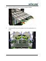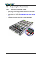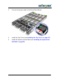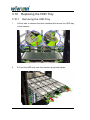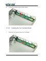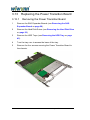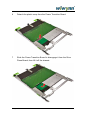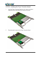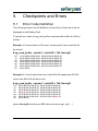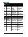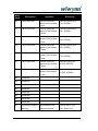
1
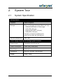
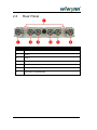
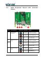
ST7110-30A Series User Manual Version 1.1 December 2014 Copyright © 2014 Wiwynn. All rights reserved. Copyright Copyright © 2014 by Wiwynn Corporation. All rights reserved. No part of this publication may be reproduced, transmitted, transcribed, stored in a retrieval system, or translated into any language or computer language, in any form or by any means, electronic, mechanical, magnetic, optical, chemical, manual or otherwise, without the prior written permission of Wiwynn Corporation. Disclaimer The information in this guide is subject to change without notice. Wiwynn Corporation makes no representations or warranties, either expressed or implied, with respect to the contents hereof and specifically disclaims any warranties of merchantability or fitness for any particular purpose. Any Wiwynn Corporation software described in this manual is sold or licensed "as is". Should the programs prove defective following their purchase, the buyer (and not Wiwynn Corporation, its distributor, or its dealer) assumes the entire cost of all necessary servicing, repair, and any incidental or consequential damages resulting from any defect in the software. 2 Wiwynn ST7110-30A User Manual Revision History No. Author Version Date Changes 1 Beth 1.0 11/26/2014 First release 2 Beth 1.1 12/30/2015 Add item 7 in safety instructions in Chapter 3. 3 Wiwynn ST7110-30A User Manual 3 Contents 1. 2. 3. 4 Preface ........................................................................................... 6 1.1 Introduction........................................................................... 6 1.2 About this Manual ................................................................. 6 System Tour ................................................................................... 7 2.1 System Specification .......................................................... 7 2.2 Front Panel ......................................................................... 8 2.3 Rear Panel.......................................................................... 9 2.4 SAS Expander Board LED Indicator Status ...................... 10 2.5 SAS Expansion Board ...................................................... 11 2.6 Drive Plane Board ............................................................ 12 2.7 Fan Controller Board ........................................................ 14 System Upgrades........................................................................ 15 3.1 Safety instructions ............................................................... 15 3.2 Recommended Tools .......................................................... 17 3.3 Replacing the Side Ear Brackets ........................................ 18 3.4 Replacing the System ......................................................... 20 3.5 Opening the System ........................................................... 24 3.6 Replacing the System Fans ................................................ 26 3.7 Replacing the SAS Expander Boards ................................. 28 3.8 Replacing the Hard Disk Drives .......................................... 30 3.9 Replacing the Power Cable................................................. 40 3.10 Replacing the HDD Tray ................................................... 44 3.11 Replacing the Bus Bar Cables .......................................... 49 3.12 Replacing the Fan Controller Board ................................. 53 3.13 Replacing the Power Transition Board .............................. 56 3.14 Replacing the Drive Plane Board ...................................... 60 3.15 Installing the Debug Card.................................................. 63 Wiwynn ST7110-30A User Manual 4. Wiwynn Supported SES Pages .................................................. 64 5. Checkpoints and Errors ............................................................. 73 5.1 Error Code Definition .......................................................... 73 Wiwynn ST7110-30A User Manual 5 1. Preface Wiwynn ST7110-30A is a unique and high-capacity storage system with high availability and flexibility 1.1 Introduction Wiwynn ST7110-30A supports up to 30 SAS hard drives in a 2U chassis. This high-density storage system is designed with redundant controllers to provide full redundant data path to each HDD. 1.2 About this Manual The contents in this manual include: Chapter 2 – describes the system specification, front and rear components, and the different boards Chapter 3 – shows how to replace the system and system components Chapter 4 – lists the Wiwynn supported SES pages Chapter 5 – lists the checkpoints and errors 6 Wiwynn ST7110-30A User Manual 2. System Tour 2.1 System Specification Storage and IO Expander SAS6G Expander Storage Thirty 3.5" hot-plug drive bays (fifteen per tray): ‧SAS/SATA SSD with 2.5" drive cage ‧SAS HDD (10K rpm) ‧Nearline SAS HDD (7.2K rpm) ‧SATA HDD (7.2K rpm) Two INT mini-SAS 6G (SASx4) ports One EXT mini-SAS 6G (SASx4) port Remote Management SES, SMP Power Supply, Physical and Packaging Specifications Power Supply Centralized 12V DC bus bar Power Consumption 300W (Idle); 400W (Max) Form Factor 2 OU rack Dimensions 93.5 (H) * 536 (W) * 795 (D) (mm) Weight 38 kg ~ 55 kg Wiwynn ST7110-30A User Manual 7 2.2 Front Panel The illustration below shows the system front panel. Item Component Item Component 1 HDD Tray 1 10 HDD Tray 2 2 External Mini SAS Connector 11 External Mini SAS Connector 3 12 4 Internal Mini SAS Connectors 13 Internal Mini SAS Connectors 5 SAS Expander Board 14 SAS Expander Board Upper Tray Primary Side 6 7 External Mini SAS Connector External Mini SAS Connector 16 8 Internal Mini SAS Connectors 17 Internal Mini SAS Connectors 9 SAS Expander Board 18 SAS Expander Board Upper Tray Secondary Side 8 Lower Tray Primary Side 15 Lower Tray Secondary Side Wiwynn ST7110-30A User Manual 2.3 Rear Panel Item Component 1 Fan 1 2 Fan 2 3 Fan 3 4 Fan 4 5 Fan 5 6 Fan 6 7 Top Cover Thumbscrews Wiwynn ST7110-30A User Manual 9 2.4 SAS Expander Board LED Indicator Status Item LED Indicator 1 External Mini SAS LED 2 Internal Mini SAS LED 3 4 Enclosure Status LED 10 LED Color LED State Status Solid Blue SAS Links Healthy Solid Red Loss of SAS Links Off No SAS Links Solid Blue SAS Links Healthy Solid Red Loss of SAS Links Off No SAS Links Solid Blue Normal System Operation Solid Red Any Error in Whole Enclosure Wiwynn ST7110-30A User Manual 2.5 SAS Expansion Board Item Connector Description 1 EXT SAS CONN External Mini SAS Connector 2 INTA SAS CONN Internal Mini SAS Connector A 3 INTB SAS CONN Internal Mini SAS Connector B 4 DEBUG Debug Header 5 PCIE CONN PCIE Connector to Drive Plane Board Wiwynn ST7110-30A User Manual 11 2.6 12 Drive Plane Board Item Connector Description 1 STRADDLE CONN Straddle Connector 2 HDD0 HDD0 Connector 3 HDD1 HDD1 Connector 4 HDD2 HDD2 Connector 5 HDD3 HDD3 Connector 6 HDD4 HDD4 Connector 7 HDD5 HDD5 Connector 8 HDD6 HDD6 Connector Wiwynn ST7110-30A User Manual Item Connector Description 9 HDD7 HDD7 Connector 10 HDD8 HDD8 Connector 11 HDD9 HDD9 Connector 12 HDD10 HDD10 Connector 13 HDD11 HDD11 Connector 14 HDD12 HDD12 Connector 15 HDD13 HDD13 Connector 16 HDD14 HDD14 Connector 17 X1PCIE_A PCIE X1 Connector A 18 X16PCIE_A PCIE X16 Connector A 19 X1PCIE_B PCIE X1 Connector B 20 X16PCIE_B PCIE X16 Connector B Wiwynn ST7110-30A User Manual 13 2.7 14 Fan Controller Board Item Connector Description 1 FAN HEADER 1 Fan 1 Connector 2 FAN HEADER 2 Fan 2 Connector 3 FAN HEADER 3 Fan 3 Connector 4 FAN HEADER 4 Fan 4 Connector 5 FAN HEADER 5 Fan 5 Connector 6 FAN HEADER 6 Fan 6 Connector 7 CN9 Power Cable Connector 1 8 CN10 Power Cable Connector 2 Wiwynn ST7110-30A User Manual 3. System Upgrades 3.1 Safety instructions Read these instructions carefully. Keep this document for future reference. Follow all warnings and instructions for your safety and to avoid damaging the system. 1 Use both hands on the Tray Handles at all times and keep the HDD tray in the horizontal position when pulling it out or pushing it in to avoid damaging the HDDs and SAS Expander Boards. 2 To avoid any injury, do not hold and use the latches or other parts of the HDD Tray to pull out or push it in. 3 For safety reason, after pulling out the HDD tray, keep holding the tray handles to prevent the HDD tray from dropping. 4 HDD latches on the HDD tray may pop out if systems are inappropriately handled during transport, for example, if it dropped upside down. This will prevent you from pulling out the upper or lower HDD tray alone. To fix this, you need to pull out the two HDD tray together, find the HDD latches that popped out and press them back into place. If you still cannot pull out the HDD tray, DO NOT FORCE IT and contact Customer Service for assistance. Wiwynn ST7110-30A User Manual 15 5 When pulling the system out of the rack for doing system upgrade, maintenance, and debug, make sure to always place the system in a flat rigid surface. Caution: DO NOT place the system on a foam pad or other non-rigid surface; doing so may cause the chassis to warp, damaging the SAS Expander Boards and damaging the drive plane board connectors while pulling out the HDD tray. 6 Before you pull out one HDD Tray, make sure the other HDD Tray is latched and secured by latch handles. 7 CAUTION: THE POWER SUPPLIES IN YOUR SYSTEM HAVE ENERGY HAZARDS, WHICH CAN CAUSE BODILY HARM. UNLESS YOU ARE INSTRUCTED OTHERWISE, ONLY TRAINED SERVICE TECHNICIANS ARE AUTHORIZED TO REMOVE THE COVERS AND ACCESS ANY OF THE COMPONENTS INSIDE THE SYSTEM. Remove the power before execute below item: - Replacing the Power cable; or - Replacing the Bus Bar Cables; or - Replacing the Fan Controller Board 16 Wiwynn ST7110-30A User Manual 3.2 Recommended Tools In performing the disassembly and assembly process, you will need the following tools: Philips screwdriver Flat screwdriver Torx screwdriver Wiwynn ST7110-30A User Manual 17 3.3 Replacing the Side Ear Brackets The system is shipped with two side ear brackets installed as a safety precaution during transport. Remove the brackets before installing the system in its rack. 3.3.1 Removing the Side Ear Brackets 1 Remove the four screws securing the side ear brackets to the chassis. 2 Detach the two side ear brackets from the chassis. 18 Wiwynn ST7110-30A User Manual 3.3.2 Installing the Side Ear Brackets 1 Place the two side ear brackets into the chassis. 2 Secure the side ear brackets to the chassis by using four screws. Tighten screws using 1.0 kgf-cm torque. Do not over-tighten screws; damage to the HDD trays may result. Wiwynn ST7110-30A User Manual 19 3.4 Replacing the System 3.4.1 Removing the System from the Rack 1 Lift the tabs to release the latch handles that secure the two HDD trays to the chassis. 2 Slide the system slowly out of the rack using two hands. 20 Wiwynn ST7110-30A User Manual 3 When the latch handles clear the rack posts, return the latch handles to the lock position (1), then slide the system out of the rack (2). Caution: The system is very heavy. Use a server lift or at least two people to lift the system into or from the rack. Wiwynn ST7110-30A User Manual 21 3.4.2 1 Installing the System into the Rack Insert the system into the chassis (1) then lift the tabs to release the latch handles (2). Caution: The system is very heavy. Use a server lift or at least two people to lift the system into or from the rack. 2 22 Push the system into the chassis. Wiwynn ST7110-30A User Manual 3 Push the latch handles until they lock into place. Wiwynn ST7110-30A User Manual 23 3.5 Opening the System 3.5.1 Removing the Top Cover 1 Remove the System from the Rack (see Removing the System from the Rack on page 20). 2 Loosen the two thumbscrews securing the top cover to the chassis. 3 Slide the top cover towards the rear and lift it off the chassis. 24 Wiwynn ST7110-30A User Manual 3.5.2 Installing the Top Cover 1 Lower the top cover onto the chassis and slide it towards the front until the thumbscrews are aligned with the screw holes. 2 Secure the top cover to the chassis by tightening the two thumbscrews. 3 Install the System into the Rack (see Installing the System into the Rack on page 22). Wiwynn ST7110-30A User Manual 25 3.6 Replacing the System Fans 3.6.1 Removing the Fan Module 1 Remove the System from the Rack (see Removing the System from the Rack on page 20). 2 Loosen the thumbscrew securing the fan module to the chassis. 3 Pull out the fan module and lift it off the chassis. 26 Wiwynn ST7110-30A User Manual 3.6.2 Installing the Fan Module 1 Insert the fan module into the chassis. 2 Secure the fan module to the chassis by tightening the thumbscrew. 3 Install the System into the Rack (see Installing the System into the Rack on page 22). Wiwynn ST7110-30A User Manual 27 3.7 Replacing the SAS Expander Boards 3.7.1 Removing the SAS Expander Board 1 Loosen the thumbscrew securing the SAS Expander Board to the HDD tray. 2 Use the two tabs to pull out the SAS Expander Board from the HDD tray. 28 Wiwynn ST7110-30A User Manual 3.7.2 Installing the SAS Expander Board 1 Insert the SAS Expander Board into the HDD tray. 2 Secure the SAS Expander Board to the HDD tray by tightening the thumbscrew. Note that only the inboard thumbscrews are used; the thumbscrews under the release levers are not screwed into the tray. Wiwynn ST7110-30A User Manual 29 3.8 Replacing the Hard Disk Drives 3.8.1 Removing the Hard Disk Drive For 3.5” Hard Disk Drive 1 Lift the tabs to release the latch handles that secure the HDD tray to the chassis. 2 Pull out the HDD tray from the chassis using both hands. 30 Wiwynn ST7110-30A User Manual 3 Press the latch that secures the HDD cover to the tray (1) and lift up the HDD cover (2). 4 Slide the HDD to disengage it from its connector and remove the HDD from the HDD tray. Wiwynn ST7110-30A User Manual 31 For 2.5” Disk Drive 1 Lift the tabs to release the latch handles that secure the HDD tray to the chassis. 2 Pull out the HDD tray from the chassis using both hands. 32 Wiwynn ST7110-30A User Manual 3 Press the latch that secures the HDD cover to the tray (1) and lift up the HDD cover (2). 4 Slide the 3.5“ drive cage to disengage the drive from its connector. Lift and remove the drive cage from the HDD tray. Wiwynn ST7110-30A User Manual 33 5 Turn over the drive cage so that the bottom side is facing up. Remove the four screws that secures the 2.5“ HDD or SSD to the cage. 6 Remove the 2.5“ HDD or SSD from the drive cage. HDD - SSD 34 Wiwynn ST7110-30A User Manual 3.8.2 Installing the Hard Disk Drive For 3.5” Hard Disk Drive 1 Insert the HDD into the tray and slide it toward the connector until it latches into place. 2 Pull down the HDD cover until it latches into place. DO NOT slam the HDD cover in place – apply pressure to the green latch while pushing the cover downwards, then release the green latch to engage the tray. Pushing the cover into place without doing this may result in shock which may damage neighboring HDDs. Applying pressure to the HDD cover will cause unbalanced force, this may result in latch non- engagement to the tray. Wiwynn ST7110-30A User Manual 35 3 Push the HDD tray into the chassis using both hands. 4 Press the HDD tray into the chassis until the handles latch into place. 36 Wiwynn ST7110-30A User Manual For 2.5” Disk Drive 1 Insert the 2.5“ HDD or SSD into the 3.5“ drive cage. HDD SSD 2 Turn over the drive cage so that the bottom side is facing up. Secure the 2.5“ HDD or SSD to the cage using four screws. Wiwynn ST7110-30A User Manual 37 3 Insert the 3.5“ drive cage into the tray and slide it toward the connector until the drive latches into place. 4 Pull down the HDD cover until it latches into place. DO NOT slam the HDD cover in place – apply pressure to the green latch while pushing the cover downwards, then release the green latch to engage the tray. Pushing the cover into place without doing this may result in shock which may damage neighboring HDDs. Applying pressure to the HDD cover will cause unbalanced force, this may result in latch non- engagement to the tray. 38 Wiwynn ST7110-30A User Manual 5 Push the HDD tray into the chassis using both hands. 6 Press the HDD tray into the chassis until the handles latch into place. Wiwynn ST7110-30A User Manual 39 3.9 Replacing the Power Cable 3.9.1 Removing the Power Cable 1 Remove the System from the Rack (see Removing the System from the Rack on page 20). 2 Remove the Top Cover (see Removing the Top Cover on page 24). 3 Disconnect the power cable from the Drive Plane Board. 40 Wiwynn ST7110-30A User Manual 4 Remove the cable clips that secure the power cable to the guide rail. 5 Disconnect the power cable from the Fan Controller Board. Wiwynn ST7110-30A User Manual 41 3.9.2 Installing the Power Cable 1 Connect the power cable to the Fan Controller Board. 2 Secure the power cable to the guide rail using cable clips. Note: Make sure that the green cables are placed at the upper side of the guard rail housing. 42 Wiwynn ST7110-30A User Manual 3 Connect the power cable to the Drive Plane Board. 4 Install the Top Cover (see Installing the Top Cover on page 25). 5 Install the System into the Rack (see Installing the System into the Rack on page 22). Wiwynn ST7110-30A User Manual 43 3.10 3.10.1 Replacing the HDD Tray Removing the HDD Tray 1 Lift the tabs to release the latch handles that secure the HDD tray to the chassis. 2 Pull out the HDD tray from the chassis using both hands. 44 Wiwynn ST7110-30A User Manual 3 Disconnect the power cable from the Drive Plane Board. 4 Loosen the thumbscrew securing the HDD tray to the guide rail. Wiwynn ST7110-30A User Manual 45 5 46 Disengage the two safety latches that secure the HDD tray to the chassis (1), then pull the HDD tray off the chassis (2). If the latches do not both push completely downwards, or if the HDD tray cannot be pulled out, push it back into the chassis approximately 1/8” (3mm) and try again. Wiwynn ST7110-30A User Manual 3.10.2 Installing the HDD Tray 1 Insert the HDD tray into the chassis, making sure the sliders are properly aligned with the rails in the chassis. 2 Secure the HDD tray to the guide rail by tightening the thumbscrew. 3 Connect the power cable to the Drive Plane Board. Wiwynn ST7110-30A User Manual 47 4 48 Press the HDD tray into the chassis until the handles latch into place. Wiwynn ST7110-30A User Manual 3.11 3.11.1 Replacing the Bus Bar Cables Removing the Bus Bar Cables 1 Remove the System from the Rack (see Removing the System from the Rack on page 20). 2 Remove the Top Cover (see Removing the Top Cover on page 24). 3 Remove the Fan Modules (see Removing the Fan Module on page 26). 4 Remove the Power Cables (see Removing the Power Cable on page 41). 5 Remove the HDD Trays (see Removing the HDD Tray on page 45). 6 Remove the five screws securing the Bus Bar Cables to the Fan Controller Board. Wiwynn ST7110-30A User Manual 49 7 Using a torx screw driver, remove the four torx screws securing the Bus Bar Cables to the chassis. 8 Lift the Bus Bar Cables off the chassis. 50 Wiwynn ST7110-30A User Manual 3.11.2 Installing the Bus Bar Cables 1 Place the Bus Bar Cables into the chassis. 2 Using a torx screw driver, secure the Bus Bar Cables to the chassis with four torx screws. Wiwynn ST7110-30A User Manual 51 3 Secure the Bus Bar Cables to the Fan Controller Board using five screws. 4 Install the HDD Trays (see Installing the HDD Tray on page 48). 5 Install the Power Cables (see Installing the Power Cable on page 43). 6 Install the Fan Modules (see Installing the Fan Module on page 27). 7 Install the Top Cover (see Installing the Top Cover on page 25). 8 Install the System into the Rack (see Installing the System into the Rack on page 22). 52 Wiwynn ST7110-30A User Manual 3.12 3.12.1 Replacing the Fan Controller Board Removing the Fan Controller Board 1 Remove the System from the Rack (see Removing the System from the Rack on page 20). 2 Remove the Top Cover (see Removing the Top Cover on page 24). 3 Remove the Fan Modules (see Removing the Fan Module on page 26). 4 Remove the Power Cables (see Removing the Power Cable on page 41). 5 Remove the HDD Trays (see Removing the HDD Tray on page 45). 6 Remove the Bus Bar Cables (see Removing the Bus Bar Cables on page 50). 7 Remove the eight screws securing the Fan Controller Board to the chassis. Wiwynn ST7110-30A User Manual 53 8 Lift the Fan Controller Board off the chassis. 3.12.2 1 54 Installing the Fan Controller Board Place the Fan Controller Board into the chassis. Wiwynn ST7110-30A User Manual 2 Secure the Fan Controller Board to the chassis using eight screws. 3 Install the Bus Bar Cables (see Installing the Bus Bar Cables on page 52). 4 Install the HDD Trays (see Installing the HDD Tray on page 48). 5 Install the Power Cables (see Installing the Power Cable on page 43). 6 Install the Fan Modules (see Installing the Fan Module on page 27). 7 Install the Top Cover (see Installing the Top Cover on page 25). 8 Install the System into the Rack (see Installing the System into the Rack on page 22). Wiwynn ST7110-30A User Manual 55 3.13 3.13.1 Replacing the Power Transition Board Removing the Power Transition Board 1 Remove the SAS Expander Boards (see Removing the SAS Expander Board on page 28). 2 Remove the Hard Disk Drives (see Removing the Hard Disk Drive on page 30). 3 Remove the HDD Trays (see Removing the HDD Tray on page 45). 4 Turn the tray over to access the base of the tray. 5 Remove the four screws securing the Power Transition Board to the chassis. 56 Wiwynn ST7110-30A User Manual 6 Detach the plastic ramp from the Power Transition Board. 7 Slide the Power Transition Board to disengage it from the Drive Plane Board, then lift it off the chassis. Wiwynn ST7110-30A User Manual 57 3.13.2 Installing the Power Transition Board 1 Insert the Power Transition Board into the chassis and slide it toward the Drive Plane Board until it latches into place. 2 Place the plastic ramp into the Power Transition Board. 58 Wiwynn ST7110-30A User Manual 3 Secure the Power Transition Board to the chassis using four screws. 4 Install the HDD Trays (see Installing the HDD Tray on page 48). 5 Install the Hard Disk Drives (see Installing the Hard Disk Drive on page 35). 6 Install the SAS Expander Boards (see Installing the SAS Expander Board on page 29). Wiwynn ST7110-30A User Manual 59 3.14 Replacing the Drive Plane Board 3.14.1 Removing the Drive Plane Board 1 Remove the SAS Expander Boards (see Removing the SAS Expander Board on page 28). 2 Remove the Hard Disk Drives (see Removing the Hard Disk Drive on page 30). 3 Remove the HDD Trays (see Removing the HDD Tray on page 45). 4 Remove the Power Transition Board (see Removing the Power Transition Board on page 57). 5 Remove the thirteen screws securing the Drive Plane Board to the chassis. 60 Wiwynn ST7110-30A User Manual 6 Remove the Drive Plane Board from the chassis 3.14.2 Installing the Drive Plane Board 1 Place the Drive Plane Board into the chassis. Wiwynn ST7110-30A User Manual 61 2 Secure the Drive Plane Board to the chassis using thirteen screws. 3 Install the Power Transition Board (see Installing the Power Transition Board on page 59). 4 Install the HDD Trays (see Installing the HDD Tray on page 48). 5 Install the Hard Disk Drives (see Installing the Hard Disk Drive on page 35). 6 Install the SAS Expander Boards (see Installing the SAS Expander Board on page 29). 62 Wiwynn ST7110-30A User Manual 3.15 Installing the Debug Card 1 Locate the port for installing the debug card. 2 Install the debug card. 3 Connect the the serial cable from the debug card to any USB port on your computer. Wiwynn ST7110-30A User Manual 63 4. Wiwynn Supported SES Pages Wiwynn SAS Expander firmware follows SES (SCSI Enclosure Services) standard so that supported SES pages can be retrieved by opening source utility such as Linux sg_ses tool. The following examples show you how to retrieve the status of some SES pages via Linux sg_ses tool. 1. Get the status of SES page0 [root@localhost ~]# sg_ses -p 0 /dev/sg1 Wiwynn Knox2U 135 Supported diagnostic pages: Supported Diagnostic Pages [sdp] [0x0] Configuration (SES) [cf] [0x1] Enclosure Status/Control (SES) [ec,es] [0x2] String In/Out (SES) [str] [0x4] Threshold In/Out (SES) [th] [0x5] Element Descriptor (SES) [ed] [0x7] Additional Element Status (SES-2) [aes] [0xa] Download Microcode (SES-2) [dm] [0xe] 64 Wiwynn ST7110-30A User Manual 2. Get the status of SES page1 [root@localhost ~]# sg_ses -p 1 /dev/sg1 Wiwynn Knox2U 135 Configuration diagnostic page: number of secondary subenclosures: 0 generation code: 0x0 enclosure descriptor list Subenclosure identifier: 0 (primary) relative ES process id: 1, number of ES processes: 1 number of type descriptor headers: 8 enclosure logical identifier (hex): 5f80f4185702a0ff enclosure vendor: Wiwynn product: Knox2U vendor-specific data: 11 22 33 44 55 00 00 00 type descriptor header/text list Element type: Array device slot, subenclosure id: 0 number of possible elements: 15 text: ArrayDevicesInSubEnclsr0 Element type: SAS connector, subenclosure id: 0 number of possible elements: 20 text: ConnectorsInSubEnclsr0 Element type: Cooling, subenclosure id: 0 number of possible elements: 12 text: CoolingElementInSubEnclsr0 Element type: Temperature sensor, subenclosure id: 0 number of possible elements: 29 text: TempSensorsInSubEnclsr0 Element type: Voltage sensor, subenclosure id: 0 number of possible elements: 12 text: VoltageSensorsInSubEnclsr0 Element type: Current sensor, subenclosure id: 0 number of possible elements: 1 text: CurrentSensorsInSubEnclsr0 Element type: Enclosure, subenclosure id: 0 number of possible elements: 1 text: EnclosureElementInSubEnclsr0 Element type: SAS expander, subenclosure id: 0 Wiwynn ST7110-30A User Manual rev: 1300 65 number of possible elements: 1 text: SAS Expander 3. Get the status of SES page2 [root@localhost ~]# sg_ses -p 2 /dev/sg1 Wiwynn Knox2U 135 Primary enclosure logical identifier (hex): 5f80f4185702a0ff Enclosure Status diagnostic page: INVOP=0, INFO=1, NON-CRIT=0, CRIT=0, UNRECOV=0 generation code: 0x0 status descriptor list Element type: Array device slot, subenclosure id: 0 [ti=0] Overall descriptor: Predicted failure=0, Disabled=0, Swap=0, status: Unsupported OK=0, Reserved device=0, Hot spare=0, Cons check=0 In crit array=0, In failed array=0, Rebuild/remap=0, R/R abort=0 App client bypass A=0, Do not remove=0, Enc bypass A=0, Enc bypass B=0 Ready to insert=0, RMV=0, Ident=0, Report=0 App client bypass B=0, Fault sensed=0, Fault reqstd=0, Device off=0 Bypassed A=0, Bypassed B=0, Dev bypassed A=0, Dev bypassed B=0 Element 0 descriptor: Predicted failure=0, Disabled=0, Swap=0, status: OK OK=1, Reserved device=0, Hot spare=0, Cons check=0 In crit array=0, In failed array=0, Rebuild/remap=0, R/R abort=0 App client bypass A=0, Do not remove=0, Enc bypass A=0, Enc bypass B=0 Ready to insert=0, RMV=0, Ident=0, Report=0 App client bypass B=0, Fault sensed=0, Fault reqstd=0, Device off=0 Bypassed A=0, Bypassed B=0, Dev bypassed A=0, Dev bypassed B=0 Element 1 descriptor: Predicted failure=0, Disabled=0, Swap=0, status: OK OK=1, Reserved device=0, Hot spare=0, Cons check=0 In crit array=0, In failed array=0, Rebuild/remap=0, R/R abort=0 App client bypass A=0, Do not remove=0, Enc bypass A=0, Enc bypass B=0 Ready to insert=0, RMV=0, Ident=0, Report=0 App client bypass B=0, Fault sensed=0, Fault reqstd=0, Device off=0 Bypassed A=0, Bypassed B=0, Dev bypassed A=0, Dev bypassed B=0 66 Wiwynn ST7110-30A User Manual ...... ...... Element type: SAS connector, subenclosure id: 0 [ti=1] Overall descriptor: Predicted failure=0, Disabled=0, Swap=0, status: Unsupported Ident=0, No information Connector physical link=0x0, Fail=0 Element 0 descriptor: Predicted failure=0, Disabled=0, Swap=0, status: OK Ident=0, SAS Drive backplane receptacle (SFF-8482) [max 2 phys] Connector physical link=0x0, Fail=0 Element 1 descriptor: Predicted failure=0, Disabled=0, Swap=0, status: OK Ident=0, SAS Drive backplane receptacle (SFF-8482) [max 2 phys] Connector physical link=0x0, Fail=0 ...... ...... Element type: Cooling, subenclosure id: 0 [ti=2] Overall descriptor: Predicted failure=0, Disabled=0, Swap=0, status: Unsupported Ident=0, Hot swap=0, Fail=0, Requested on=0, Off=0 Actual speed=0 rpm, Fan stopped Element 0 descriptor: Predicted failure=0, Disabled=0, Swap=0, status: OK Ident=0, Hot swap=0, Fail=0, Requested on=0, Off=0 Actual speed=5350 rpm, Fan at intermediate speed Element 1 descriptor: Predicted failure=0, Disabled=0, Swap=0, status: OK Ident=0, Hot swap=0, Fail=0, Requested on=0, Off=0 Actual speed=4650 rpm, Fan at intermediate speed ...... ...... Element type: Temperature sensor, subenclosure id: 0 [ti=3] Overall descriptor: Predicted failure=0, Disabled=0, Swap=0, status: Unsupported Ident=0, Fail=0, OT failure=0, OT warning=0, UT failure=0 UT warning=0 Temperature: <reserved> Wiwynn ST7110-30A User Manual 67 Element 0 descriptor: Predicted failure=0, Disabled=0, Swap=0, status: OK Ident=0, Fail=0, OT failure=0, OT warning=0, UT failure=0 UT warning=0 Temperature=30 C Element 1 descriptor: Predicted failure=0, Disabled=0, Swap=0, status: OK Ident=0, Fail=0, OT failure=0, OT warning=0, UT failure=0 UT warning=0 Temperature=32 C ...... ...... Element type: Voltage sensor, subenclosure id: 0 [ti=4] Overall descriptor: Predicted failure=0, Disabled=0, Swap=0, status: Unsupported Ident=0, Fail=0, Warn Over=0, Warn Under=0, Crit Over=0 Crit Under=0 Voltage: 0.00 volts Element 0 descriptor: Predicted failure=0, Disabled=0, Swap=0, status: OK Ident=0, Fail=0, Warn Over=0, Warn Under=0, Crit Over=0 Crit Under=0 Voltage: 1.19 volts Element 1 descriptor: Predicted failure=0, Disabled=0, Swap=0, status: OK Ident=0, Fail=0, Warn Over=0, Warn Under=0, Crit Over=0 Crit Under=0 Voltage: 3.24 volts ...... ...... Element type: Current sensor, subenclosure id: 0 [ti=5] Overall descriptor: Predicted failure=0, Disabled=0, Swap=0, status: Unsupported Ident=0, Fail=0, Warn Over=0, Crit Over=0 Current: 0.00 amps Element 0 descriptor: Predicted failure=0, Disabled=0, Swap=0, status: OK Ident=0, Fail=0, Warn Over=0, Crit Over=0 68 Wiwynn ST7110-30A User Manual Current: 23.87 amps Element type: Enclosure, subenclosure id: 0 [ti=6] Overall descriptor: Predicted failure=0, Disabled=0, Swap=0, status: Unsupported Ident=0, Time until power cycle=0, Failure indication=0 Warning indication=0, Requested power off duration=0 Failure requested=0, Warning requested=0 Element 0 descriptor: Predicted failure=0, Disabled=0, Swap=0, status: OK Ident=0, Time until power cycle=0, Failure indication=0 Warning indication=0, Requested power off duration=0 Failure requested=0, Warning requested=0 Element type: SAS expander, subenclosure id: 0 [ti=7] Overall descriptor: Predicted failure=0, Disabled=0, Swap=0, status: Unsupported Ident=0, Fail=0 Element 0 descriptor: Predicted failure=0, Disabled=0, Swap=0, status: OK Ident=0, Fail=0 4. Get the status of SES page7 [root@localhost ~]# sg_ses -p 7 /dev/sg1 Wiwynn Knox2U 135 Primary enclosure logical identifier (hex): 5f80f4185702a0ff Element Descriptor In diagnostic page: generation code: 0x0 element descriptor by type list Element type: Array device slot, subenclosure id: 0 [ti=0] Overall descriptor: ArrayDevicesInSubEnclsr0 Element 0 descriptor: ArrayDevice00 Element 1 descriptor: ArrayDevice01 ...... Element type: SAS connector, subenclosure id: 0 [ti=1] Overall descriptor: ConnectorsInSubEnclsr0 Element 0 descriptor: Connector00 Element 1 descriptor: Connector01 Wiwynn ST7110-30A User Manual 69 ...... Element type: Cooling, subenclosure id: 0 [ti=2] Overall descriptor: CoolingElementInSubEnclsr0 Element 0 descriptor: Fan 1 Front Element 1 descriptor: Fan 1 Rear ...... Element type: Temperature sensor, subenclosure id: 0 [ti=3] Overall descriptor: TempSensorsInSubEnclsr0 Element 0 descriptor: DPB Temp. Sensor 1 Element 1 descriptor: DPB Temp. Sensor 2 ...... Element type: Voltage sensor, subenclosure id: 0 [ti=4] Overall descriptor: VoltageSensorsInSubEnclsr0 Element 0 descriptor: SEB Voltage 1.2V Element 1 descriptor: SEB Voltage 3.3V ...... Element type: Current sensor, subenclosure id: 0 [ti=5] Overall descriptor: CurrentSensorsInSubEnclsr0 Element 0 descriptor: Current Sensor 1 Element type: Enclosure, subenclosure id: 0 [ti=6] Overall descriptor: EnclosureElementInSubEnclsr0 Element 0 descriptor: Knox Enclosure Element type: SAS expander, subenclosure id: 0 [ti=7] Overall descriptor: SAS Expander Element 0 descriptor: Top ExpanderB 70 Wiwynn ST7110-30A User Manual 5. Get the status of SES page10 [root@localhost ~]# sg_ses -p 10 /dev/sg1 Wiwynn Knox2U 135 Primary enclosure logical identifier (hex): 5f80f4185702a0ff Additional element status diagnostic page: generation code: 0x0 additional element status descriptor list Element type: Array device slot, subenclosure id: 0 [ti=0] Element index: 0 Transport protocol: SAS number of phys: 1, not all phys: 0, device slot number: 0 phy index: 0 device type: end device initiator port for: target port for: SSP attached SAS address: 0x5f80f4185702a0ff SAS address: 0x5000cca024370892 phy identifier: 0x1 Element index: 1 Transport protocol: SAS number of phys: 1, not all phys: 0, device slot number: 1 phy index: 0 device type: end device initiator port for: target port for: SSP attached SAS address: 0x5f80f4185702a0ff SAS address: 0x5000cca02437102a phy identifier: 0x1 ...... ...... Element type: SAS expander, subenclosure id: 0 [ti=7] Element index: 0 Transport protocol: SAS number of phys: 28 SAS address: 0x5f80f4185702a0ff [0] connector element index: 0, other element index: 14 [1] connector element index: 1, other element index: 4 Wiwynn ST7110-30A User Manual 71 [2] connector element index: 2, other element index: 9 [3] connector element index: 3, other element index: 3 [4] connector element index: 4, other element index: 2 [5] connector element index: 5, other element index: 8 [6] connector element index: 6, other element index: 7 [7] connector element index: 7, other element index: 1 [8] connector element index: 8, other element index: 0 [9] connector element index: 9, other element index: 13 [10] connector element index: 10, other element index: 6 [11] connector element index: 11, other element index: 5 [12] connector element index: 12, other element index: 10 [13] connector element index: 13, other element index: 11 [14] connector element index: 14, other element index: 12 ...... ...... 72 Wiwynn ST7110-30A User Manual 5. Checkpoints and Errors 5.1 Error Code Definition The following listed is the full definition of Knox Error Code and it will be displayed on the Debug Card. To get all error code via sg_read_buffer command with buffer id 0x76 as follows. Example 1. Current status is “No error” means byte 0 (error code 0) will be set as 1. # sg_read_buffer --mode=1 --id=0x76 -l 100 /dev/sgX 00 10 20 30 40 50 60 01 00 00 00 00 00 00 00 00 00 00 00 00 00 00 00 00 00 00 00 00 00 00 00 00 00 00 00 00 00 00 00 00 00 00 00 00 00 00 00 00 00 00 00 00 00 00 00 00 00 00 00 00 00 00 00 00 00 00 00 00 00 00 00 00 00 00 00 00 00 00 00 00 00 00 00 00 00 00 00 00 00 00 00 00 00 00 00 00 00 00 00 00 00 00 00 00 00 00 00 Example 2. Current status has error code 50 & 94 means byte 50 & 94 (error code 50 & 94) will be set as 1. # sg_read_buffer --mode=1 --id=0x76 -l 100 /dev/sgX 00 10 20 30 40 50 60 00 00 00 00 00 00 00 00 00 00 00 00 00 00 00 00 00 00 00 00 00 00 00 00 00 00 01 00 00 00 00 00 00 00 00 00 00 00 00 00 00 00 00 00 00 00 00 00 00 00 00 00 00 00 00 00 00 00 00 00 00 00 00 00 00 00 00 00 00 00 00 00 00 00 00 00 00 00 00 00 00 00 00 00 00 00 00 00 00 00 00 00 00 00 00 00 00 00 01 00 where /dev/sgX should be an SES device (such as sg1, sg2, ...) Wiwynn ST7110-30A User Manual 73 Error Code 00 No error 01 Expander A fault 02 03 04 05 06 74 Description Expander B fault I2C bus A crash I2C bus B crash I2C bus C crash I2C bus D crash Condition Event Log Expander A Critical-Expander ID heartbeat stop 0 HB Stop Expander B Critical-Expander ID heartbeat stop 1 HB Stop Cannot query I2C Critical-I2C Bus ID device in I2C bus A 0 Crash Cannot query I2C Critical-I2C Bus ID device in I2C bus B 1 Crash Cannot query I2C Critical-I2C Bus ID device in I2C bus C 2 Crash Cannot query I2C Critical-I2C Bus ID device in I2C bus D 3 Crash 07 Reserved 08 Reserved 09 Reserved 10 Reserved 11 Fan 1 front fault Cannot query fan speed in fan module 1 front* Critical-Cooling ID 0 Fail, X(RPM) 12 Fan 1 rear fault Cannot query fan speed in fan module 1 rear* Critical-Cooling ID 1 Fail, X(RPM) 13 Fan 2 front fault Cannot query fan speed in fan module 2 front* Critical-Cooling ID 2 Fail, X(RPM) 14 Fan 2 rear fault Cannot query fan speed in fan module 2 rear* Critical-Cooling ID 3 Fail, X(RPM) 15 Fan 3 front fault Cannot query fan speed in fan module 3 front* Critical-Cooling ID 4 Fail, X(RPM) Wiwynn ST7110-30A User Manual Error Code Description Condition Event Log 16 Fan 3 rear fault Cannot query fan speed in fan module 3 rear* Critical-Cooling ID 5 Fail, X(RPM) 17 Fan 4 front fault Cannot query fan speed in fan module 4 front* Critical-Cooling ID 6 Fail, X(RPM) 18 Fan 4 rear fault Cannot query fan speed in fan module 4 rear* Critical-Cooling ID 7 Fail, X(RPM) 19 Fan 5 front fault Cannot query fan speed in fan module 5 front* Critical-Cooling ID 8 Fail, X(RPM) 20 Fan 5 rear fault Cannot query fan speed in fan module 5 rear* Critical-Cooling ID 9 Fail, X(RPM) 21 Fan 6 front fault Cannot query fan speed in fan module 6 front* Critical-Cooling ID 10 Fail, X(RPM) 22 Fan 6 rear fault Cannot query fan speed in fan module 6 rear* Critical-Cooling ID 11 Fail, X(RPM) 23 Reserved 24 Reserved 25 Reserved 26 Reserved 27 Reserved 28 Reserved 29 Reserved 30 Reserved 31 DPB temp. sensor 1 Temperature over Critical-Temp. ID 0 warning Fail, Temp=X(C) Wiwynn ST7110-30A User Manual critical threshold 75 Error Code 32 33 34 35 Description 37 38 39 40 41 42 Event Log DPB temp. sensor 2 Temperature over Critical-Temp. ID 1 warning Fail, Temp=X(C) critical threshold DPB temp. sensor 3 Temperature over Critical-Temp. ID 2 warning Fail, Temp=X(C) critical threshold DPB temp. sensor 4 Temperature over Critical-Temp. ID 3 warning Fail, Temp=X(C) critical threshold SEB temp. sensor A Temperature over warning 36 Condition Critical-Temp. ID 4 critical threshold Fail, Temp=X(C) SEB temp. sensor B Temperature over Critical-Temp. ID 5 warning critical threshold Fail, Temp=X(C) Ambient temp. Temperature over Critical-Temp. ID 6 sensor A1 warning critical threshold Fail, Temp=X(C) Ambient temp. Temperature over Critical-Temp. ID 7 sensor A2 warning critical threshold Fail, Temp=X(C) Ambient temp. Temperature over Critical-Temp. ID 8 sensor B1 warning critical threshold Fail, Temp=X(C) Ambient temp. Temperature over Critical-Temp. ID 9 sensor B2 warning critical threshold Fail, Temp=X(C) BJT temp. sensor 1 Temperature over Critical-Temp. ID 10 warning critical threshold* Fail, Temp=X(C) BJT temp. sensor 2 Temperature over Critical-Temp. ID 11 warning critical threshold* Fail, Temp=X(C) 43 Reserved 44 Reserved 45 SEB voltage sensor Voltage over or under Critical-Voltage ID? Fail, warning V=X(mV) critical threshold (ID: Voltage sensor on SEB) 76 Wiwynn ST7110-30A User Manual Error Code 46 Description Condition Event Log DPB voltage sensor Voltage over or under Critical-Voltage ID? Fail, warning V=X(mV) critical threshold (ID: Voltage sensor on DPB) 47 FCB voltage sensor Voltage over or under Critical-Voltage ID? Fail, warning V=X(mV) critical threshold* (ID: Voltage sensor on FCB) 48 FCB current sensor Current over or under Critical-Current ID 0 warning critical threshold* Fail, I=X(mA) 49 Reserved 50 HDD0 SMART HDD0 Temperature Critical-Temp. ID 12 temp. warning over critical threshold Fail, Temp=X(C) HDD1 SMART HDD1 Temperature Critical-Temp. ID 13 temp. warning over critical threshold Fail, Temp=X(C) HDD2 SMART HDD2 Temperature Critical-Temp. ID 14 temp. warning over critical threshold Fail, Temp=X(C) HDD3 SMART HDD3 Temperature Critical-Temp. ID 15 temp. warning over critical threshold Fail, Temp=X(C) HDD4 SMART HDD4 Temperature Critical-Temp. ID 16 temp. warning over critical threshold Fail, Temp=X(C) HDD5 SMART HDD5 Temperature Critical-Temp. ID 17 temp. warning over critical threshold Fail, Temp=X(C) HDD6 SMART HDD6 Temperature Critical-Temp. ID 18 temp. warning over critical threshold Fail, Temp=X(C) HDD7 SMART HDD7 Temperature Critical-Temp. ID 19 temp. warning over critical threshold Fail, Temp=X(C) HDD8 SMART HDD8 Temperature Critical-Temp. ID 20 temp. warning over critical threshold Fail, Temp=X(C) HDD9 SMART HDD9 Temperature Critical-Temp. ID 21 temp. warning over critical threshold Fail, Temp=X(C) 51 52 53 54 55 56 57 58 59 Wiwynn ST7110-30A User Manual 77 Error Description Code Condition Event Log 60 HDD10 SMART HDD10 Temperature Critical-Temp. ID 22 temp. warning over critical threshold Fail, Temp=X(C) HDD11 SMART HDD11 Temperature Critical-Temp. ID 23 temp. warning over critical threshold Fail, Temp=X(C) HDD12 SMART HDD12 Temperature Critical-Temp. ID 24 temp. warning over critical threshold Fail, Temp=X(C) HDD13 SMART HDD13 Temperature Critical-Temp. ID 25 temp. warning over critical threshold Fail, Temp=X(C) HDD14 SMART HDD14 Temperature Critical-Temp. ID 26 temp. warning over critical threshold Fail, Temp=X(C) Expander A Internal Expander A Internal Critical-Temp. ID 27 temp. warning Temperature over critical threshold Fail, Temp=X(C) 61 62 63 64 65 66 Critical-Temp. ID 28 temp. warning Temperature over critical threshold Fail, Temp=X(C) HDD0 Array Device Critical-HDD Slot 0 Element status fault Status Fault HDD1 Array Device Critical-HDD Slot 1 Element status fault Status Fault HDD2 Array Device Critical-HDD Slot 2 Element status fault Status Fault HDD3 Array Device Critical-HDD Slot 3 Element status fault Status Fault HDD4 Array Device Critical-HDD Slot 4 Element status fault Status Fault 67 Reserved 68 Reserved 69 Reserved 70 HDD0 fault 71 72 73 74 78 Expander B Internal Expander B Internal HDD1 fault HDD2 fault HDD3 fault HDD4 fault Wiwynn ST7110-30A User Manual Error Code Description Condition Event Log 75 HDD5 fault HDD5 Array Device Critical-HDD Slot 5 Element status fault Status Fault HDD6 Array Device Critical-HDD Slot 6 Element status fault Status Fault HDD7 Array Device Critical-HDD Slot 7 Element status fault Status Fault HDD8 Array Device Critical-HDD Slot 8 Element status fault Status Fault HDD9 Array Device Critical-HDD Slot 9 Element status fault Status Fault HDD10 Array Device Critical-HDD Slot 10 Element status fault Status Fault HDD11 Array Device Critical-HDD Slot 11 Element status fault Status Fault HDD12 Array Device Critical-HDD Slot 12 Element status fault Status Fault HDD13 Array Device Critical-HDD Slot 13 Element status fault Status Fault HDD14 Array Device Critical-HDD Slot 14 Element status fault Status Fault 76 77 78 79 80 81 82 83 84 HDD6 fault HDD7 fault HDD8 fault HDD9 fault HDD10 fault HDD11 fault HDD12 fault HDD13 fault HDD14 fault 85 Reserved 86 Reserved 87 Reserved 88 Reserved 89 Reserved 90 External Mini-SAS Loss of SAS links Critical-Connector link error (x1~x3) ID 16 Loss Link(s) 91 Internal Mini-SAS 1 Loss of SAS links Critical-Connector link error ID 20 Loss Link(s) Wiwynn ST7110-30A User Manual (x1~x3) 79 Error Code Description 92 Internal Mini-SAS 2 Loss of SAS links Critical-Connector link error (x1~x3) ID 24 Loss Link(s) Self tray be pulled F/W detect self tray be Critical-Self Tray Be out pulled out* 93 94 Condition Event Log Pulled Out Peer tray be pulled F/W detect peer tray Critical-Peer Tray out be pulled out* Be Pulled Out Only show this error N/A 95 Reserved 96 Reserved 97 Reserved 98 Reserved 99 Firmware and hardware not match code when FW initialization and then FW will hang* N/A Self tray be pushed F/W detect self tray be Infomation-Self in N/A pushed in Tray Be Pushed In Peer tray be pushed F/W detect peer tray Information-Peer in Tray Be Pushed In be pushed in Notes: 80 - ( * ) Error code may be caused by cable issues (physical damage, incorrect installation or disconnected cables) - When flashing SEB firmware and reset for it to take effect, the RAID volume will become unconfigured, bad and foreign. Due to eeprom update process during reset, the connection between SEB and RAID card will be temporarily off, thus causing the RAID volume to be in offline state. It’ll require a manual configuration and import for it to restore to its original state. Wiwynn ST7110-30A User Manual - When manually adjusting HDD LED while HDD is present in the slot (i.e. forcibly changing blue to red, or blue to off), due to the nature of LSI RAID card, it’ll change the LED back to its original state as it reckons the drive is still present. - An errata for SEB F/W has a chance to report invalid (fake) Fan speed and FCB voltage during error handling for sensor reading. If this happens, the F/W will just record an event in the event log. After that, the sensor reading will become normal. This event does not affect the system and can be ignored. This issue might occur on SEB F/W version 21.14.00.04 or earlier versions. - Error 99: an error code of 99 will be displayed on debug card along with full rotation rpm on all the fans when SAS Expander Board (SEB) are mixed among Knox & Cold Storage. - HDD SMART temperature error code of 50 to 64 will not be visually displayed on debug card nor through wknoxutil -- showdebugid when storage system is populated with SATA drives. - SAS HDD temperature polling is disabled by default from Expander FW version 21.14.00.04. Wiwynn ST7110-30A User Manual 81 - 82 HDD location Wiwynn ST7110-30A User Manual