1
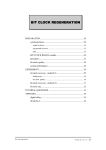
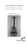
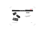
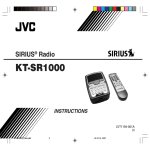
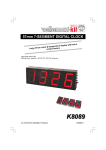
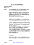
General guidelines for assembly, safety
and electromagnetic compatibility
For more info about all our kits,
please visit our Web-site :
http://www.velleman.be
K6000
1
RS
While the soldering iron is heating, read this first !
You want to enjoy your Velleman Kit as quick as possible, these hints will assist
you !
First, take your time. Hasty jobs often result in disappointments. Make sure your
workspace is wide, clean and well lit. Collect all the necessary tools you might
need for the assembly. Take care, while unpacking that nothing is left in the
wrapping or boxes, such as small parts, manuals and leaflets. Please check if all
components are present. Use the supplied partlist as a guide. In case there is
something missing or damaged, return the Kit to your dealer. Read all supplied
manuals and notes carefully before you start constructing...
The Velleman Kit Warranty
Please read this carefully. In most cases, you can easily solve problems yourself.
This text tells you all about.
The Kit, you have built or intend to build, was design by a team of highly skilled
design engineers. Before their design reaches the customer, it has been tested
and re-tested over and over again. This procedure guarantees you that every
design actually works, when it is put together in the right way. But what if
something does go wrong ?
Avoid unnecessary expenses and loss of time ! Examine the whole circuit closely.
An even better procedure is to let someone else do this for you. Every tiny detail
is important. Are all components put in the right place and correctly oriented.
Watch out for bad or forgotten solder joints and short-circuits ! What about the
power supply ? Is it correct and present ? Does the Kit require special calibration
or adjustment ? Do the possible external devices such as computers, audio
sources or power circuits match the Kit specifications ?
When all the above did not bring you any closer to a solution, start thinking of a
defective part or parts. Semiconductors like transistors, FET’s, IC’s and
processors, although very reliable do not support abuse. You can send us
suspect semiconductors for inspection and eventual exchange but keep in mind.
Our experienced technicians can tell the difference between a defective and a
fried transistor, and in several cases a stamp is much more expensive than a
replacement semiconductor bought at the local store.
Any Velleman-Kit if defective will be repaired or replaced at our option within 30
days of purchase.
Simply return it to the place of purchase with proof of purchase.
K6000
2
RS
ASSEMBLY STEPS
Required tools to assemble the kit :
Use a small soldering iron of max. 40W.
Use thin (1mm) solder, do not use any flux.
Use a small cutter to trim excess wires.
n
n
n
n
•
‚
Mount the components
against the PCB surface
and carefully solder the
leads in place.
Obtain cone-shaped shiny
soldered joints by heating
up the component leads
sufficiently.
ƒ
„
This solder joint results in
a bad connection.
Trim the excess wires up to
the level of the solder.
Careless assembly will certainly lead to problems
Insert the part, oriented correctly, into its correct holes in the PCB.
Mount the components in the correct order as stated in the manual.
Use the boxes m to check off your progress.
F Before starting to build, read also the general guidelines.
K6000
3
RS
1.
10.
11.
RV...
2.
RV...
RV...
12.
3.
13.
4.
L...
L...
14.
5.
6.
CV..
CV...
15.
7.
16.
8.
17.
CATHODE
9.
+
18.
-
K6000
4
RS
F...
19.
F...
V~
I= A
Kit n°: K
Hz
W F=
A
20.
21.
SW...
SW...
22.
23.
24.
25.
K6000
5
RS
General guidelines for assembly, safety
and electromagnetic compatibility
Soldering:
1. Mount the components against the
PCB surface and carefully solder
the leads in place.
2. Obtain cone-shaped, shiny soldered
joints by heating up the component
leads sufficiently.
3. This solder joint gives a bad
connection.
4. Snip off the excess lead up to the
level of the solder.
Components:
1. Resistor
2. Potentiometer
3. Trimmer potentiometer
4. Coil
5. Capacitor
6. Trimmer capacitor
7. Electrolytic capacitor
8. Diode
9. Rectifier bridge
10. Zener diode
11. LED (light emitting diode)
12. IC socket
13. IC (integrated circuit)
14. Transistor
15. Voltage regulator
16. Triac
17. Diac
18. PCB pin
19. Fuse holder
20. Pushbutton
21. Switch
K6000
22.
23.
24.
25.
Relay
Crystal
Transformator
Screw connector
General guidelines for power supply and
any shielding :
• Preferably use an approved AC adapter
or batteries. If this is not possible
because the kit has to be connected
directly to the AC-outlet, then carefully
follow the guidelines below:
• Mount the kit in a suitable plastic
housing.
• If a metal housing is needed for
screening purposes, then the housing
must be grounded.
• Use a mains switch if the device
consumes more than 10W (Power
consumption = Mains voltage x Current).
• If applicable, use a isolated transformer.
• Use a double pole AC-outlet switch for
kits that are connected to the AC-outlet
without a transformer.
• Use a robust AC-outlet lead with clamp,
or use a AC-outlet input connector.
• Use well insulated cable for AC-outlet
voltage cabling with a minimum area of
cross-section of 0.75mm² .
• Attach the sticker supplied (26) to the
housing, and fill in the AC-outlet voltage,
frequency, power consumption or
current, and the value of the fuse.
6
RS
MICRO PROCESSOR CONTROLLER/TIMER
In addition to the features of an ordinary week/day switching clock, this jewel of a
controller allows controlling independant temperatures through one or all four of its
outputs.
For every temperature to be measured (up to 4) a separate sensor K6001 or
K6003 is required, which allows to install the controller itself distant from the
measuring point. When a sensor becomes defective, the controller outputs a
message on the screen and switches the corresponding output off. Any relevant
information like output number, temperature or on/off, day and time is displayed
through an illuminated LC display.
Programming the device (up to 200 steps!) is done through a clear "menu"
structure. Just like with an ordinary thermostat you can readjust the
preprogrammed settings temporarily and set a hysteresis per output. In order to
save programming work in the case of a mains voltage drop, the print has been
designed such that it can be fitted with a NiCd or ordinary 9V battery.
TECHNICAL DATA
- 4 noisefree relay outputs max. 5A
- 4 opto coupler inputs for temperature sensors K6001 or K6003
- Allows to supply up to four sensors type K6001
- Detection of the presence and operation of temperature sensors
- 16 character LCD screen (illuminated)
- 50 program steps per output (200 in total)
- Allows either week or day program
- Programming resolution: 1 minute and 0.1°
- Hysteresis adjustable from 0 to 25° (0,1° per step) separately per output.
- Accuracy: +/-0.1°
- Measuring range: -40° to +150°
- Sampling frequency: 1 sec.
- 24 hour clock with day indication
- LED indication of the output states
- Standard version intended for building in
- Separately obtainable housing B6000 for building up
- Supply voltage: mains
- Memory back up: 24 hours with 9V battery / 8 hours with 4.8V NiCd battery
- Dimensions (front panel): 235X120mm. Building-in depth min. 50mm
Modifications reserved
K6000
7
RS
ASSEMBLY
A) Assembly of the keyboard module P6000S
q-Fit D5 through D9, 1N4148 type small signal diodes or equivalent. Pay attention
to the polarity!
q-Fit the push buttons SW1 through SW5, with their bodies AGAINST the pcb.
REMARK: Don't warm up the terminals of the push buttons too long, because this
might damage the push buttons irreparably!
B) Assembly of the basic module P6000B
q-Fit the wire jumpers marked J on the pcb
q-The wire jumper between IC3 and IC5 (dotted-lined and marked "WRITE
PROTECT") must be fitted in the first instance. If afterwards you want to prevent
the established program from getting overwritten, then you'll have to cut this wire
jumper. Wire jumper JC should not be fitted for the present.
Fit the following components when using a 9V battery for memory backup:
q- D10, diode from the 1N4148 series or equivalent. Pay attention to the polarity!
q- ZD2, 3.3V zener diode. Pay attention to the polarity!
q- T6, BC557C type transistor or equivalent.
Fit the following components when using a NiCd battery for memory backup:
q- Wire jumper JC
q- D27, diode from the 1N4148 series or equivalent. Pay attention to the polarity!
q- D26, diode from the 1N4000 series or equivalent. Pay attention to the polarity!
Fit the following resistors:
q- R1 through R6, 1K (brown, black, red)
q- R7, 4K7 (yellow, violet, red)
q- R8 through R12, 47K (yellow, violet, orange)
q- R22 through R31, 4K7 (yellow, violet, red)
q- R32, 10M (brown, black, blue)
q- R33, 1K (brown, black, red)
q- R34, 680 ohm (blue, grey, brown)
q- R35, 1/2W 220 ohm (red, red, brown, white)
Fit the following diodes: (pay attention to the polarity)
q- D1 through D4, diode from the 1N4148 series or equivalent.
q- D11 through D15, diode from the 1N4148 series or equivalent
q- D16 through D25, diode from the 1N4000 series.
q- ZD1, 7.5V zener diode.
q-Fit the IC sockets for IC1 through IC9
q-Fit push button SW6 (see also REMARK above in point A)
K6000
8
RS
q-Fit the 4K7 resistor network RA1. Such a network consists of nine resistors
connected together at one end and accomodated in one single housing. The
common is marked with a notch, a dot or a stripe, and must correspond with the
hole marked "C".
q-Fit 2 pcb pins for GND and TP
q-T1 through T5, BC547 type or equivalent. Transistors
q-Fit the 4.1943MHz crystal X1. Crystal
q-Fit the 7806 type voltage regulator VR1, with its metal back towards D26.
Fit the following capacitors:
q-C1, 5pF ceramic (sometimes marked 4.7)
q-C2, 39pF ceramic
q-C3 through C5, 100nF (sometimes marked u1 or 104)
q-C6, 10uF electrolytic capacitor. Pay attention to the polarity!
q-C7, 2200uF electrolytic capacitor. Pay attention to the polarity!
q-C8 and C9, 470uF. Pay attention to the polarity!
q-Fit the fuse holder F1 and fit it with a 0.4A fuse.
q-Fit the 4 six-pole connectors J1 through J4.
q-Fit the relays RY1 through RY4.
Assembly of the noise suppressing networks for the outputs:
q-Fit the capacitors C10 through C13, 100nF 400V or higher. Fit these
capacitors vertically and with only one lead connected for the present.
q-Fit the following 220 ohm 1/2W resistors also vertically and with only one
lead connected for the present:
When using the "normally closed (NC)" contact of the relay, fit resistor R37,
R39, R41, R43 for output 1, 2, 3, 4 respectively.
When however using the "normally open (NO)" contact, fit resistor R36, R38,
R40, R42 for output 1, 2, 3, 4 respectively. Then connect the free extremities of
each capacitor-resistor pair together and cut them.
K6000
9
RS
q-Apply an extra layer of solder to the soldered copper traces.
q-Connect the 9V battery holder (when not using a NiCd battery) to the - points
(black wire) and to one of the two + holes (red wire) of E1.
q-Fit the 12V/100mA transformer TRANSFO 2.
q-Fit the 2X6V (12V) / 300mA transformer TRANSFO 1. Check the position of the
12V output.
Fit the following components on the solder side. Do this very carefully because
afterwards some of these components will have to fit under or to pass through the
front panel. Be also careful when soldering because for some of the components
you have to heat close by the component body:
q- RV1, 4K7 (5K) trimming potentiometer.
q- CV1, 30pF trimming capacitor.
q- the LED's LD1 through LD5 (LD5= red) with their tops at a height of 14mm
above the pcb surface. To do so first solder one lead of the LED, then correct its
position and finally solder its second lead. Pay attention to the polarity, the
shortest lead should correspond with the flat side of the circle on the pcb
overprint.
At this point, before proceeding, check the whole mounting once more
thoroughly as well as the solder side for soldering mistakes!
Fitting the keyboard module onto the basic module
ca. 7mm
P6000S
P6000S
10mm SPACER
P6000S
P6000S
SOLDERSIDE
SOLDERSIDE
P6000B
P6000B
Solder six uninsulated wires to the points KB, S1 through S5 at the solder side of
the keyboard pcb. These wires will serve afterwards to make the connections with
the basic module.
REMARK: Cut the superfluous extremities of these wires FLUSH with the pcb
surface at the component side!
K6000
10
RS
SOLDER
Fit the keyboard pcb into the four holes at the solder side of the basic pcb. See that
the connection wires (KB, S1..S5) pass through the basic pcb too and that the
connection point KB corresponds with the hole marked "1" at the solder side of the
basic pcb. Fix the keyboard pcb using four M2.5 nuts. See that the pcb is perfectly
parallel with the basic pcb, because only then you can solder and cut the
connections at the component side of the basic pcb.
Fitting the display onto the basic module
LCD MODULE
M2.5 BOLT
INSULATING SLEEVE
5mm SPACER
SOLDERSIDE
M2.5 NUT
P6000B
Check that, where the display has to be fitted, the solder points on the basic pcb
are cut short. BE SHURE TO CUT the solder points from SW6!.
Fit the dislay at the solder side of the basic pcb using four M2.5 bolts together with
four 5mm spacers and an additional insulation ring. Fix the display using four M2.5
nuts at the component side of the basic pcb and check that the display is at right
angles to the basic pcb. Now connect by means of uninsulated wires, the display
with the base PCB (see fig.).
LCD TYPE A
LCD TYPE B
.
Insert the following IC's:
q-IC1, VK6000 or PIC16C57 type, with its notch towards the transformer.
q-IC2, HCT4060 type or equivalent, with its notch towards IC3.
K6000
11
RS
q-IC3, 74HC373 type or equivalent, with its notch towards the pcb edge.
q-IC4, 74HC373 type or equivalent, with its notch towards SW6.
q-IC5, 6116 type or equivalent, with its notch towards IC3.
q-Fit IC6 through IC9, TIL111 or 4N27 type opto couplers or equivalent, with
their notches towards C8.
Before fitting the front panel and the battery we will first test the circuit.
TEST AND CONNECTION
a) Test without temperature sensors:
Connect the mains voltage to the points MAINS.
ATTENTION: CERTAIN POINTS OF THE PCB NOW CARRY DANGEROUS
MAINS VOLTAGE.
Normally, the display should show the text "1;OFF Mo 00:00" now. Should this not
be the case, just turn the contrast trimming potentiometer. Using the push buttons
SW2 and SW3 (second and third from the left) you now should be able to "select"
among the four outputs. (the output number is the first digit on the display)
ATTENTION: Should the controller not work, then try to unblock by just pressing
the RESET push button next to IC4. This RESET button may be used every time
the controller 'locks up'. Attention, pressing the RESET button erases the memory
content.
b) Test with temperature sensors: (K6001 or K6003)
Before doing the following test, first disconnect the mains voltage.
Connect one or more sensors to the points SENSOR1 through SENSOR4, and
branch off the power supply for the K6001 type sensors from the points Vsensor +
and -. (see fig. 6.0)
The power supply for the K6003 type sensors has to be made separately, or
replace TRANSFO 2 by a 2X6V/1A type (see fig. 6.1).
Now switch the power back on. Normally, for these outputs equipped with a sensor,
the display should indicate a temperature now, instead of "OFF" (selection of the
outputs is again done using the buttons SW2 and SW3). The display indicating
"SENSOR ERROR" or simply keeping indicating "OFF" for a certain output means
that this sensor is defective or wrongly connected.
See USER MANUAL if you want to test all the functions before fixing the front
panel.
After a successful test, you may fit a 9V battery. Fix the battery with a binder or with
a piece of two-sided adhesive tape. When using a NiCd battery you may fit two
2.4V batteries or one 4.8V battery in the place marked E1.
REMARK: With a NiCd battery, the memory back-up will not work until the
controller will have been powered on for a few weeks. (this is the time needed to
charge the NiCd battery).
K6000
12
RS
K6000/K6010
MAINS
Vsensor
+
SENSOR4 SENSOR3 SENSOR2 SENSOR1
+
+
+
+
MAINS
SENSOR OUT -
+
K6001
SENSOR OUT -
+
K6001
SENSOR OUT -
+
K6001
SENSOR OUT -
K6001
K6000
+
FIG. 6.0
13
RS
K6000/K6010
TRANSFO2
6
0
6V/1A
6
MAINS
Vsensor
+
SENSOR4 SENSOR3 SENSOR2 SENSOR1
+
+
+
+
MAINS
6V/1A
SENSOR OUT -
+
K6003
SENSOR OUT -
+
K6003
SENSOR OUT -
+
K6003
SENSOR OUT -
K6003
K6000
+
FIG. 6.1
14
RS
ADJUSTMENT
ATTENTION: WHEN THE CIRCUIT IS POWERED ON, A LOT OF POINTS
CARRY DANGEROUS MAINS VOLTAGE.
As the clock of the controller must continue working during a power failure, we
opted for an oscillator based clock built round a crystal and a devider. If you don't
adjust the clock, it may go wrong after a certain period of time. Adjusting can be
done in two different ways:
1) Using a frequency counter:
Connect the counter to the points GND(earth) and TP. The frequency measured
must be of 256KHz i.e. a period of 3.90625mS. The time base can be adjusted
using trimming capacitor CV1.
2) at sight:
Of course the first method is the best one but as only few of us possess a
frequency counter, the second method will be the most frequently used one. Turn
the trimming capacitor CV1 to its centre position (the fixed and movable plates
must overlap by about half their surfaces). Should in course of time the clock go
wrong, then you would have to readjust the trimming capacitor CV1 a little. To that
end the front panel contains a hole through which the clock can be adjusted.
FIXING THE FRONT PANEL
M3 BOLT
P6000B
8mm THREAD TUBE
SOLDERSIDE
5mm THREAD TUBE
M3 BEVELLED HEAD BOLT
ALU FRONT PANEL
Fit each of the six sunk holes with an 8mm and 10mm spacer using an M3
bevelled head bolt.
ATTENTION: Fix these screws WELL because, with the foil sticked, they will no
longer be accessible.
Before sticking the self-adhesive foil to the aluminium front pate, check that the
surface contains no wire-edges, dirt or other obstacles.
Position the foil onto the front panel (pay attention to the LED windows OUT1, ...).
Provisionally adhere one half of the foil using adhesive tape. Remove the
protective sheet from the other half and stick this side, then remove the adhesive
tape and the protective sheet from the first half and stick this half to the aluminium
front plate too. Fit the basic module onto the thread tubes using six M3 bolts and
check that the indication LED's and LCD display are well positioned, also check the
operation of the push buttons. The controller is now ready for use.
K6000
15
RS
D5
D6
D7
D8
SW5
D9
NC
4
NO
NC
3
NO
NC
2
NO
NC
1
NO
SLOW
0.4A
F1
J2
J1
C12
C11
R43
RY4
RY3
RY2
RY1
12VAC
TRANSFO2
R42 C13
R40
R41
R38
R39
R37
R36
LD1 T2
LD2 T3
LD5
J
LD4
MAINS
J
6
J3
+
-
+
-
1
D15
6
1
IC9
TRANSFO1
0
12VAC
+
D14
IC8
-
C7
J4
1
+
-
D13
IC7
D17
D19
D18
D16
VR1
C3
9 VOLT
BATTERY
ZD2
D26
+
1
J J J J
IC6
C9
D12
C4
Vsensor SENSOR4 SENSOR3 SENSOR2 SENSOR1
-
C8
E1
1X4.8V OR 2X2.4V
Ni-Cd BATTERY
VELLEMAN
P6000B'4
LD3 T4
T6
JC
D10
D27
R12
T1
J
R31
IC2
256Hz
TP
J
J
D11
SW6
RESET
J
RA1
J
R32
CV1
C5 CLOCK
C1 ADJUST
C
X1
1
J 1
J
J
IC4
C2
C6
J
1
WRITE PROTECT
J
J
IC3
R5
GND
J
D20
D1
R1
D22
R22
R23
R24
R25
D2
R2
D3
R3
D4
R4
R33
J
J
J
IC1
J
LDKEYBOARD
PCB
ZD1
R6
R30
RV1
DISPLAY
CONTRAST
T5
J
LCD MODULE
DY1
IC5
R7
C10
D25
16
SW4
D24
SW3
D23
R9
D21
R8
LD+LD
LD+
D7
D6
D5
D4
D3
D2
D1
D0
E
RW
RS
Vo
Vdd
GND
S5
S4
S3
S2
S1
KB
SW2
R11
KB 1 2 3 4 5
R34
MAN
R10
R35
K6000
+LD
SW1
R26
R27
R28
R29
1
1
VELLEMAN P6000S'2
ENTER
RUN
RS
K6000
17
RS