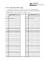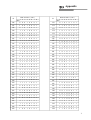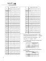
1
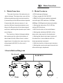
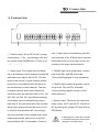
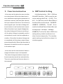
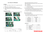
Alarm Box User Manual
Before use the product, please read this manual carefully.
TABLE OF CONTENT
Main Feature………………………………………………………………… … …11
Main Function……………………………………………………………………1 1
Installation Diagram………… ……………………………………………………22
Connection ………………………………………………………………………3 3
Function instruction……………………………………………………………….44
DIP Switches Setting………………………………………………………………4
The Alarm Box ID Setting…………………………………………………… ……5
Factory default setting……… ……………………………………………………99
Keyboard operation………………………………………………………………10
Debugging……………………………………………………………………… …12
12
1212
Installation……………………………………………………………………… …
…13
Technical Data………………… ………………………………………………… 13
…13
Trouble Shooting………………………………………………………………… 13
Main Function
1. Main Function
The main function of the alarm box is
2. Main Features
Ø IP66 waterproof design.
alarm linkage. The alarm box can call the
Ø Power supply 9V-24V AC/DC.
different presets quickly and automatica-
Ø RS485 of the dome and the keyboard
lly according to the different alarm signals.
controlling by DIP switches, 2400bps,
Connected with a dome camera, it can
4800bps, 9600bps baud rates selectable.
monitor different important places accor-
Ø Setting the alarm box ID (0-255) by
ding to the Sequence of the alarm signal
setting DIP Switches.
acquired, realizing the dynamic spot video
Ø With the function of arm and disarm.
surveillance.
Ø Setting the attribute (NO/NC) of the
The function of alarm linkage enables
alarm box relay input by the keyboard.
the system get the video information of
Ø Setting the alarm input port number of
alarm spot quickly. When there is alarm
the alarm box in accordance with the
signal input, the alarm box can output two
dome presets by keyboard.
relay signals (NO/NC) for the user's
Ø With the function of alarm spot memory.
reference.
Ø Setting the reset mode and interval time
after alarming by keyboard.
3.Installation Diagram
Keyboard
Rs485 BUS
Alarm Box
Dome
1
Installation Diagram
Magnifying Drawing
J1 J2 J3 J4 J5 J6 J7 J8 J9 J10 J11 J12 J13 J14 J15 J16
PO WE R
In1
In2
In3
In4
In5
In6
ALARM INPUT
Power Supply
Alarm Input
In7
In8
J17 J18
J19 J20
RA+ RB-
TA+ TB-
Rs485
Rs485
Rs485 Input
J21 J22 J23 J24
OUT1
Alarm Output
(Keyboard)
Rs485 Output
(Dome)
Alarm box relay input (1 to 8 channel):
There are two cables connected up relaysignal in each channel.
If the sensor conn-ected with the N channel is Number The relay
input attribute of this channel should be set to Number.otherwise
NC.
2
OUT2
ALARM OUTPUT
Connection
4. Connection
J1 J2 J3 J4 J5 J6 J7 J8 J9 J10 J11 J12 J13 J14 J15 J16
POWER
①
In1
In2
In3
J17 J18
J19 J20
RA+ RB-
TA+ TB-
ALARM INPUT
Rs485
Rs485
②
③
④
In4
In5
In6
In7
In8
J21 J22 J23 J24
OUT1
OUT2
ALARM OUTPUT
⑤
① Power supply: AC or DC 9V-24V, power
only 7 alarm input channelbeing used the
consumption ≥1W; , connecting to the two
two terminals of the 8 thalarm input channel
ter minals in the POWER port. (There is no
should be short circuit or open circuit. Ac-
“+”,“-”.)
cording to the reply inputs attribute.
② Alarm input: First make sure the attrib-
③ RS485 input controlling cable: connec-
ute of the sensor in each channel connected
ting to the RA+ and RB- terminals.
with alarm box input is NO or NC. The attr-
(The controllingsignal is from keyboard)
ibute of the sensor in each channel should
be strictly in accordance with the alarm in-
④ Rs485 output controlling cable: conne-
put attribute set in each channel. The first
cting to the TA+ and TB- terminals.
to eighth channel alarm input should be
(The controlling signal is output to the
connected with the two terminals in IN1, In2,
dome camera.)
IN3, IN4, In5,IN6, IN7, and IN8 accordingly.
If the alarm input channels being used is
⑤ Alarm output: There are two channels
less than 8, the two terminals of the unused
relay output, OUT1 and OUT2. Set NO or
alarm input channel should be short circuit
NC by setting the jumper JP5 and JP6 on
to set the relay attribute NC. Accordingly
PCB Board.
the two terminals of the unused alarm input
channel should be open circuit to set the
reply attribute NO. For example, if there is
NOTICE
Conducting the connection carefully
to avoid misconnection as the connecting ports is joined closely.
3
Function instruction
6. DIP Switch Setting
5. Function instruction
Ø User can set the alarm box arm or disa-
As following below,SW1、SW2 are
rm via keyboard. When the alarm box is
8-bitsDIP Switches,SW1is used for ala-
arm, besides accepting the operation to it
rm box setting with ID No.(0-255),The
and dome camera, the alarm box detects
bit 5、6 of Sw2 are used for Baud Rate of
the input status all the time. Once there is
the Alarm Box and the dome(2400BPS、
alarm signal input, the alarm linkage will
4800BPS、9600BPS).,The bit7、8 are
be activated, as well as the alarm output.
used for the Baud Rate of Alarm Box and
When the alarm input signal disappears,
the Keyboard(2400bps、4800bps、
the alarm linkage will keep on working u-
9600BPS).The first four bits of SW2 is for
ntil the alarm linkage is manually reset or
setting factory default,and there is no
automatically reset (via the keyboard co-
other function temporarily. The resetdip
ntroller). Only after the alarm linkage res-
switch setting is not effective unless it is
et completely will the alarm output disap-
initializing again
pear automatically. When the alarm box is
disarmed, the alarm box will not respond
to the alarm input.
Ø User can set the reset mode of alarm linkage and alarm output via keyboard.
The alarm linkage and alarm output can
be set manually as well as automatically.
The auto-reset interval time can be set via keyboard.
NO
Sw1
J1 J2 J3 J4 J5 J6 J7 J8 J9 J10 J11 J12 J13 J14 J15 J16
P O WE R
In1
In2
In3
In4
In5
ALARM INPUT
4
NC
NO
NC
Sw2
In6
In7
In8
J17 J18
J19 J20
RA+ RB-
TA+ TB-
Rs485
Rs485
J21 J22 J23 J24
OUT1
OUT2
ALARM OUTPUT
Appendix
7. The Alarm Box ID Setting
The alarm box ID number(0-255)is set by setting the DIP Switch Sw1,
Detailed setting refer to the table below.The circle “1”means the DIP switch
setting should be “ON”;the circle “0”means “OFF”.
ID
D I P S w i t c h e s (SW1)
(Bit) 1
2
3
4
5
6
7
8
0
ID
D I P S w i t c h e s (SW 1)
(Bit) 1
2
3
4
5
6
7
8
34
0
1
0
0
0
1
0
0
1
1
0
0
0
0
0
0
0
35
1
1
0
0
0
1
0
0
2
0
1
0
0
0
0
0
0
36
0
0
1
0
0
1
0
0
3
1
1
0
0
0
0
0
0
37
1
0
1
0
0
1
0
0
4
0
0
1
0
0
0
0
0
38
0
1
1
0
0
1
0
0
5
1
0
1
0
0
0
0
0
39
1
1
1
0
0
1
0
0
6
0
1
1
0
0
0
0
0
40
0
0
0
1
0
1
0
0
7
1
1
1
0
0
0
0
0
41
1
0
0
1
0
1
0
0
8
0
0
0
1
0
0
0
0
42
0
1
0
1
0
1
0
0
9
1
0
0
1
0
0
0
0
43
1
1
0
1
0
1
0
0
0
1
1
0
1
0
0
10
0
1
0
1
0
0
0
0
44
0
11
1
1
0
1
0
0
0
0
45
1
0
1
1
0
1
0
0
12
0
0
1
1
0
0
0
0
46
0
1
1
1
0
1
0
0
13
1
0
1
1
0
0
0
0
47
1
1
1
1
0
1
0
0
14
0
1
1
1
0
0
0
0
48
0
0
0
0
1
1
0
0
15
1
1
1
1
0
0
0
0
49
1
0
0
0
1
1
0
0
16
0
0
0
0
1
0
0
0
50
0
1
0
0
1
1
0
0
17
1
0
0
0
1
0
0
0
51
1
1
0
0
1
1
0
0
18
0
1
0
0
1
0
0
0
52
0
0
1
0
1
1
0
0
19
1
1
0
0
1
0
0
0
53
1
0
1
0
1
1
0
0
20
0
0
1
0
1
0
0
0
54
0
1
1
0
1
1
0
0
21
1
0
1
0
1
0
0
0
55
1
1
1
0
1
1
0
0
22
0
1
1
0
1
0
0
0
56
0
0
0
1
1
1
0
0
23
1
1
1
0
1
0
0
0
57
1
0
0
1
1
1
0
0
24
0
0
0
1
1
0
0
0
58
0
1
0
1
1
1
0
0
1
0
1
1
1
0
0
25
1
0
0
1
1
0
0
0
59
1
26
0
1
0
1
1
0
0
0
60
0
0
1
1
1
1
0
0
27
1
1
0
1
1
0
0
0
61
1
0
1
1
1
1
0
0
28
0
0
1
1
1
0
0
0
62
0
1
1
1
1
1
0
0
29
1
0
1
1
1
0
0
0
63
1
1
1
1
1
1
0
0
30
0
1
1
1
1
0
0
0
64
0
0
0
0
0
0
1
0
31
1
1
1
1
1
0
0
0
65
1
0
0
0
0
0
1
0
32
0
0
0
0
0
1
0
0
66
0
1
0
0
0
0
1
0
33
1
0
0
0
0
1
0
0
67
1
1
0
0
0
0
1
0
5
Appendix
ID
6
D I P S w i t c h e s (SW 1)
ID
D I P S w i t c h e s (SW1)
(Bit) 1
(Bit) 1
2
3
4
5
6
7
8
68
0
0
1
0
0
0
1
0
102
0
69
1
0
1
0
0
0
1
0
70
0
1 1
0
0
0
1
71
1 1 1
0
0
0
72
0
0
0
1
0
73
1
0
0
1
74
0
1
0
75
1 1
0
76
0
77
2
3
4
5
6
7
8
1 1
0
0
1 1
0
103
1 1 1
0
0
1 1
0
0
104
0
0
0
1
0
1 1
0
1
0
105
1
0
0
1
0
1 1
0
0
1
0
106
0
1
0
1
0
1 1
0
0
0
1
0
107
1 1
0
1
0
1 1
0
1
0
0
1
0
108
0
0
1 1
0
1 1
0
1
0
0
1
0
109
1
0
1 1
0
1 1
0
0
1 1
0
0
1
0
110
0
1 1 1
0
1 1
0
1
0
1 1
0
0
1
0
111
1 1 1 1
0
1 1
0
78
0
1 1 1
0
0
1
0
112
0
0
0
0
1 1 1
0
79
1 1 1 1
0
0
1
0
113
1
0
0
0
1 1 1
0
80
0
0
0
0
1
0
1
0
114
0
1
0
0
1 1 1
0
81
1
0
0
0
1
0
1
0
115
1 1
0
0
1 1 1
0
82
0
1
0
0
1
0
1
0
116
0
0
1
0
1 1 1
0
83
1 1
0
0
1
0
1
0
117
1
0
1
0
1 1 1
0
84
0
0
1
0
1
0
1
0
118
0
1 1
0
1 1 1
0
85
1
0
1
0
1
0
1
0
119
1 1 1
0
1 1 1
0
86
0
1 1
0
1
0
1
0
120
0
0
0
1 1 1 1
0
87
1 1 1
0
1
0
1
0
121
1
0
0
1 1 1 1
0
88
0
0
0
1 1
0
1
0
122
0
1
0
1 1 1 1
0
89
1
0
0
1 1
0
1
0
123
1 1
0
1 1 1 1
0
90
0
1
0
1 1
0
1
0
124
0
0
1 1 1 1 1
0
91
1 1
0
1 1
0
1
0
125
1
0
1 1 1 1 1
0
92
0
0
1 1 1
0
1
0
126
0
1 1 1 1 1 1
0
93
1
0
1 1 1
0
1
0
127
1 1 1 1 1 1 1
0
94
0
1 1 1 1
0
1
0
128
0
0
0
0
0
0
0
1
95
1 1 1 1 1
0
1
0
129
1
0
0
0
0
0
0
1
96
0
0
0
0
0
1 1
0
130
0
1
0
0
0
0
0
1
97
1
0
0
0
0
1 1
0
131
1 1
0
0
0
0
0
1
98
0
1
0
0
0
1 1
0
132
0
0
1
0
0
0
0
1
99
1 1
0
0
0
1 1
0
133
1
0
1
0
0
0
0
1
100
0
0
1
0
0
1 1
0
134
0
1 1
0
0
0
0
1
101
1
0
1
0
0
1 1
0
135
1 1 1
0
0
0
0
1
Appendix
ID
D I P S w i t c h e s (SW1)
(Bit) 1
2
3
4
5
6
7
8
136
0
0
0
1
0
0
0
1
137
1
0
0
1
0
0
0
138
0
1
0
1
0
0
139
1 1
0
1
0
140
0
0
1 1
141
1
0
142
0
ID
D I P S w i t c h e s (SW1)
(Bit) 1
2
3
4
5
6
7
170
0
1
0
1
0
1
0
1
1
171
1 1
0
1
0
1
0
1
0
1
172
0
0
1 1
0
1
0
1
0
0
1
173
1
0
1 1
0
1
0
1
0
0
0
1
174
0
1
1 1
0
1
0
1
1 1
0
0
0
1
175
1 1 1 1
0
1
0
1
1 1 1
0
0
0
1
176
0
0
0
0
1 1
0
1
143
1 1 1 1
0
0
0
1
177
1
0
0
0
1 1
0
1
144
0
0
0
0
1
0
0
1
178
0
1
0
0
1 1
0
1
145
1
0
0
0
1
0
0
1
179
1 1
0
0
1 1
0
1
0
1
0
1 1
0
1
8
146
0
1
0
0
1
0
0
1
180
0
147
1 1
0
0
1
0
0
1
181
1
0
1
0
1 1
0
1
148
0
0
1
0
1
0
0
1
182
0
1
1
0
1 1
0
1
149
1
0
1
0
1
0
0
1
183
1 1 1
0
1
1
0
1
150
0
1 1
0
1
0
0
1
184
0
0
0
1 1 1
0
1
151
1 1 1
0
1
0
0
1
185
1
0
0
1 1 1
0
1
152
0
0
0
1 1
0
0
1
186
0
1
0
1 1 1
0
1
153
1
0
0
1 1
0
0
1
187
1 1
0
1 1
1
0
1
154
0
1
0
1 1
0
0
1
188
0
0
1 1 1
1
0
1
155
1 1
0
1 1
0
0
1
189
1
0
1 1 1
1
0
1
156
0
0
1 1 1
0
0
1
190
0
1 1 1 1 1
0
1
157
1
0
1 1 1
0
0
1
191
1 1 1 1 1 1
0
1
158
0
1 1 1
1
0
0
1
192
0
0
0
0
0
0
1 1
159
1 1 1 1 1
0
0
1
193
1
0
0
0
0
0
1 1
160
0
0
0
0
0
1
0
1
194
0
1
0
0
0
0
1 1
161
1
0
0
0
0
1
0
1
195
1 1
0
0
0
0
1 1
162
0
1
0
0
0
1
0
1
196
0
0
1
0
0
0
1 1
163
1 1
0
0
0
1
0
1
197
1
0
1
0
0
0
1 1
164
0
0
1
0
0
1
0
1
198
0
1
1
0
0
0
1 1
165
1
0
1
0
0
1
0
1
199
1 1 1
0
0
0
1 1
166
0
1 1
0
0
1
0
1
200
0
0
0
1
0
0
1 1
167
1 1 1
0
0
1
0
1
201
1
0
0
1
0
0
1 1
168
0
0
0
1
0
1
0
1
202
0
1
0
1
0
0
1 1
169
1
0
0
1
0
1
0
1
203
1 1
0
1
0
0
1 1
7
Appendix
ID
8
D I P S w i t c h e s (SW1)
D I P S w i t c h e s ( SW1)
ID
(Bit)1
(Bit)1
2
3
4
5
6
7
204
0
0
1 1
0
0
1 1
238
0
205
1
0
1 1
0
0
1 1
206
0
1 1 1
0
0
207
1 1 1 1
0
208
0
0
0
0
209
1
0
0
210
0
1
211
4
5
6
1 1 1
0
1 1 1
239
1 1 1 1
0
1 1 1
1 1
240
0
0
0
0
1 1 1 1
0
1 1
241
1
0
0
0
1 1 1 1
1
0
1
1
242
0
1
0
0
1 1 1 1
0
1
0
1
1
243
1 1
0
0
1 1 1 1
0
0
1
0
1
1
244
0
0
1
0
1 1 1 1
1 1
0
0
1
0
1 1
245
1
0
1
0
1 1 1 1
212
0
0
1
0
1
0
1
1
246
0
1 1
0
1 1 1 1
213
1
0
1
0
1
0
1
1
247
1 1 1
0
1 1 1 1
214
0
1 1
0
1
0
1 1
248
0
0
0
1 1 1 1 1
215
1 1 1
0
1
0
1 1
249
1
0
0
1 1 1 1 1
216
0
0
0
1 1
0
1 1
250
0
1
0
1 1 1 1 1
217
1
0
0
1 1
0
1 1
251
1 1
0
1 1 1 1 1
218
0
1
0
1 1
0
1 1
252
0
0
1 1 1 1 1 1
219
1 1
0
1 1
0
1 1
253
1
0
1 1 1 1 1 1
220
0
1 1 1
0
1 1
254
0
1 1 1 1 1 1 1
25 5
Prog rammab le Addr ess
1
1 1 1 1 1 1 1
0
8
221
1
0
1 1 1
0
1 1
222
0
1 1 1 1
0
1 1
223
1 1
1 1 1
0
1 1
224
0
0
0
0
0
1 1 1
225
1
0
0
0
0
1 1 1
226
0
1
0
0
0
1 1 1
227
1 1
0
0
0
1 1 1
228
0
0
1
0
0
1 1 1
229
1
0
1
0
0
1 1 1
230
0
1 1
0
0
1 1 1
231
1 1 1
0
0
1 1 1
232
0
0
0
1
0
1 1 1
233
1
0
0
1
0
1 1 1
234
0
1
0
1
0
1 1 1
235
1 1
0
1
0
1 1 1
236
0
0
1 1
0
1 1 1
237
1
0
1
1
0
1
1
1
2
3
7
8
The alarm box baud rate setting:(SW2)
As the chart bellow, the circle “1”means
the DIP switch setting should be “ON”;
the circle “0”means “OFF”
1、The baud rate setting of the alarm box
and the keyboard
Baud Rate
2400bps
4800bps
9600bps
D I P S w i t c h (Sw2)
(Bit) 5
6
0
0
1
0
0
1
2、The baud rate setting of the alarmbox
and the dome
Baud Rate
2400bps
4800bps
9600bps
D I P S w i t c h (Sw2)
(Bit) 7
8
0
0
1
0
0
1
Factory default setting
8. Factory default setting
6. Set the attribute of the alarm input and
● The factory default alarm input and ou-
input. Enter the submenu of Alarm box I/O
tput attributes are NO.
setup via keyboard.
● The 1-8 input channel of the alarm box
7. Port NO: input alarm input channel nu-
is corresponding to the 1-8 preset of the
dome. (Channel 1 to preset 1, channel 2
the preset corresponding to the alarm
mber (1-8), input 0 to respond to all the 8
channels.
8. Status: The attribute of the alarm input
to preset 2).
channel: 1 for NO, 0 for NC.
● The alarm box ID is 1.
9. Preset: The preset corresponding to the
● The alarm box baud rate is 4800BPS.
channel. (1-80)
● The alarm box is auto-reset, the auto-
10. The sensor connected to IN7 is NC in
reset interval time is 5sec.
● The alarm box is arm.
the normal status. If the sensor sends an
open relay input to the alarm box in the
alarm situation, operate as follows to
make the dome point to the preset 7, for
detail operations as follow:
9.Keyboard operation
1. Connect the alarm box with the keyboard and dome camera referring to diagram .
NOTICE
2. Set the dome with ALEC protocol and
1) Input 7 for the Port No and press Enter;
2) Input 0 for the Status and press Enter;
3) Input 7 for the Preset and press Enter;
4) The 7th input is end up.
the same baud rate with the alarm box.
The dome ID is random.
3. Set the alarm box ID.
4. Electrify to alarm box and keyboard,
and set the baud rate of the keyboard
same to the alarm box.
5. When user conduct the operation to
dome by keyboard, the dome ID number
should be set the same as the ID number
of the alarm box connected with the dome
so as to fulfill the operation to the dome.
(For example, turn up, down, left, right,
set preset and call preset.)
9
Keyboard operation
9.1 Set all alarm inputs as ON,
for detail operations as follow:
9.3 Reset the alarm linkage
1) Input 0 for the Port No and press Enter
3 to enter Alarm acknowledge. The screen
2) Input 1 for the Status and press Enter
will appear input port No:
3) Input 0 for the Preset and press Enter
2) Input 1-8 to reset the corresponding
4) End to input
alarm input linkage. Input 0 and press
1) In the submenu of Alarm setup, input
ENTER to reset all the channels alarm
linkage.For example:
User can input 1 as well as 0, then
press ENTER to reset the first alarm
9.2 Arm disarm and reset mode
setting
1) In the submenu of Alarm setup, input 2
to enter Alarm enable.
2) Press 1 to switch from arm(Alarm:ON)/
disarm(Alarm:OFF)state.
3) Press“REV”“NEXT” to plus or minus the value of Reset: (0 to 50) of the
reset (the value means the auto reset interval time). Press “DEL”key to set the
value 0, which means manually reset. The
auto-reset time is 5 times the value of the
reset seconds. For example, if the value
is 1, the auto-reset time is 5 seconds, if
the value is 2, the auto-reset time is 10
seconds.
4) Press Enter to confirm the setting.
10
input channel.
Keyboard operation
10. Debugging
Ø Do the first 5 steps according to 8 keyboard operation, the keyboard could conduct the operation to the dome. If it can not
control, check each step carefully.
●
It is suggested that user check if the
keyboard can control the dome without
connecting to the alarm box.
●
Check if the power supply of the ala-
rm box is connected to the alarm box correctly
●
Check if the input and output of the
Rs485 is connected correctly.
Ø If it is ok and the dome can be control-
11. Installation
Ø If the system works well after the debugging, let all the cables across the cable aperture into the alarm box, screw the
waterproof nut tightly.
Ø Add a waterproof pat on the alarm pat
on the alarm box housing and screw tightly with screws to avoid leakage.
Ø
The cable aperture should be down-
ward when fixing the alarm box.
Ø User takes all the responsibilities if
he doesn't install the alarm box according
to the manual and result in the circuit damage for rain leakage.
ler by the keyboard set 8 presetsand call
the presets to ensure 8 presets have been
set in the dome. Firstclose the circuit of
the N Channel (1≤N≤8), open the circuit
of the otherchannels, the dome should point to preset N. If there is no action with
the dome, set all the alarm box input NO
via keyboard, set the N alarm input channel corresponding to preset N (1≤N≤8),
then set the alarm box arm.
Ø Connect the sensors in all the channels to the alarm box. If the sensor is NC,
set the alarm box relay input NC after the
connection and power on.
Ø Test the system using the connected
sensor. If there is no action with the dome,
check if there is open circuit in connection
lines and if the sensor works well.
11
Keyboard operation
12. Technical Data
Power Supply
≥9V and ≤12V (AC or Dc)
Power Consumption
≤1W
Alarm Output
0.4A,125VAC;2A,30VDC
Weight
Sending and Receiving Controlling Mode
Rs485
Sending and Receiving Baud Rate
2400BPS,4800BPS,9600BPS
The Furthest Transferring Distance(0.5mm twisted-pair)
1200m
Environment Temperature
0℃~+50℃
Dimensions
200*120*75(mm)
13. Trouble Shooting
Problem
The keyboard can not control
the dome. There is no alarm
linkage. There is no alarm
output when changing the
alarm input status. The alarm
box does not work.
The keyboard can not control
the dome, There is alarm
linkage when changing the
alarm input status.
There is alarm linkage, while
the keyboard can not control
the dome.
The keyboard can control alarm
box, but can not control the
dome, there is no alarm linkage.
The keyboard can control the
dome, but there is no alarm
linkage.
12
Possible Cause
Solution
Bad connection of power cable.
Connect correctly.
The badness of power supply.
Change the power supply.
1、The wrong setting of the
keyboard board rate;
2、The bad connection of the
keyboard and the alarm box;
3、No connection.
1、The bad connection of the dome
and alarm box;
2、No connection;
3、The baud rate of keyboard and
alarm box is not in accordance.
1. The bad connection of the
keyboard and alarm box;
2. The baud rate of the dome and
alarmbox is not in accordance.
1、The bad connection of the alarm
box and the dome.
2、The baud rate of the dome and the
alarm box is not in accordance.
1、Bad connection of the alarm
input cable;
2、The connection cable open
circuit;
1. Reset the keyboard baud rate;
2. Connect the keyboard and
alarm box correctly.
1、Connect the dome and alarm
box correctly;
2、Reset the dome baud rate.
1、Connect the keyboard and
alarm box correctly;
2、Reset the keyboard baud rate.
1、Connect the alarm box and
dome correctly.
2、Reset the dome baud rate.
Connect the alarm input cable
correctly.
Alarm Box User Manual
Version V1.00