1
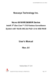
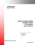
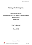
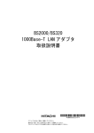
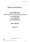
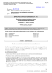
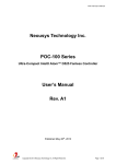
PCIe-PoE354at/PCIe-PoE352at User’s Manual
Neousys Technology Inc.
PCIe-PoE354at/PCIe-PoE352at
4-Port / 2-Port Server-grade Gigabit 802.3at PoE+
Frame Grabber Card
User’s Manual
Rev. A1
Published Jun 18th, 2015
Copyright © 2015 Neousys Technology Inc. All Right Reserved.
Page 1 of 31
PCIe-PoE354at/PCIe-PoE352at User’s Manual
Date
Description
Version
2015/06/18
First formal release
A1
Copyright © 2015 Neousys Technology Inc. All Right Reserved.
Page 2 of 31
PCIe-PoE354at/PCIe-PoE352at User’s Manual
Contents
Declaimer................................................................................................................................................... 4
Declaration of Conformity.............................................................................................................. 4
FCC.........................................................................................................................................4
CE........................................................................................................................................... 4
Copyright and Trademarks............................................................................................................ 4
Chapter 1 Introduction.............................................................................................................................5
1.1 Overview..................................................................................................................................... 5
1.2 Product Specification............................................................................................................... 6
1.2.1 Specification of PCIe-PoE354at............................................................................6
1.2.2 Specification of PCIe-PoE352at............................................................................6
Chapter 2 Know your PCIe-PoE354at/352at....................................................................................7
2.1 Unpacking your PCIe-PoE354at/352at............................................................................... 7
2.2 PCIe-PoE354at Top View....................................................................................................... 7
2.3 PCIe-PoE352at Top View....................................................................................................... 8
Chapter 3 Getting Start...........................................................................................................................9
3.1 Configure Board ID of PCIe-PoE354at/352at....................................................................9
3.2 Configure 12 VDC Source (PCIe-PoE354at Only)......................................................... 11
3.3 Install the PCIe-PoE352at....................................................................................................12
3.4 Install the PCIe-PoE354at Frame Grabber Card............................................................14
3.5 Connect a PoE or Non-PoE Device...................................................................................16
Chapter 4 Driver Installation and Settings...................................................................................... 17
4.1 Driver Installation....................................................................................................................17
4.1.1 Install Driver Using “One-Click” Driver Installation.........................................17
4.1.2 Install Driver Manually...........................................................................................18
4.2 Driver Settings.........................................................................................................................19
4.2.1 Jumbo Frame.......................................................................................................... 19
4.2.2 Receive Buffer.........................................................................................................21
4.2.3 Transmit Buffers......................................................................................................24
Appendix A Using Per-Port PoE On/Off Control.............................................................................27
A.1 Driver Installation................................................................................................................... 27
A.2 Per-Port On/Off Control Function Reference.................................................................. 29
PCI_GetStatusPoEPort................................................................................................... 29
PCI_EnablePoEPort.........................................................................................................30
PCI_DisablePoEPort........................................................................................................31
Copyright © 2015 Neousys Technology Inc. All Right Reserved.
Page 3 of 31
PCIe-PoE354at/PCIe-PoE352at User’s Manual
Declaimer
This manual is intended to be used as a practical and informative guide only and is subject
to change without prior notice. It does not represent commitment from Neousys Technolgy
Inc. Neousys shall not be liable for direct, indirect, special, incidental, or consequential
damages arising out of the use of the product or documentation, nor for any infringements
upon the rights of third parties, which may result from such use.
Declaration of Conformity
FCC
This equipment has been tested and found to comply with the limits for a Class A digital
device, pursuant to part 15 of the FCC Rules. These limits are designed to provide
reasonable protection against harmful interference when the equipment is operated in a
commercial environment. This equipment generates, uses, and can radiate radio frequency
energy and, if not installed and used in accordance with the instruction manual, may cause
harmful interference to radio communications. Operation of this equipment in a residential
area is likely to cause harmful interference in which case the user will be required to correct
the interference at his own expense.
CE
The product(s) described in this manual complies with all applicable European Union (CE)
directives if it has a CE marking. For computer systems to remain CE compliant, only
CE-compliant parts may be used. Maintaining CE compliance also requires proper cable
and cabling techniques.
Copyright and Trademarks
This document contains proprietary information protected by copyright. All rights are
reserved. No part of this document may be reproduced by any mechanical, electronic, or
other means in any form without prior written permission of the manufacturer.
Company/product names mentioned herein are used for identification purposes only and
are trademarks and/or registered trademarks of their respective companies.
Copyright © 2015 Neousys Technology Inc. All Right Reserved.
Page 4 of 31
PCIe-PoE354at/PCIe-PoE352at User’s Manual
Chapter 1 Introduction
1.1 Overview
PCIe-PoE354at is world’s first PoE frame grabber card combing server-grade GigE
controller and 802.3at PoE+ capability. Inheriting Neousys’ expertise in PoE technology,
PCIe-PoE354at further implements the updated 802.3at-2009 standard and offers up to
25.5W of power each port.
PCIe-PoE354at is designed with state-of-the-art Intel® I350 Gigabit Ethernet controller.
This server-grade GigE controller incorporates advanced features, such as checksum
offloading, segmentation offloading and intelligent interrupt generation/moderation, to
increase overall Ethernet performance and reduce CPU utilization. In addition, its
single-bus, multi-port topology minimizes the compatibility issue with off-the-shelf
motherboards when installing multiple cards.
Machine vision applications can be benefited by PCIe-PoE354at’s server-grade network
performance. Its 25.5W PoE+ can now power PTZ (pan-tilt-zoom) cameras for surveillance
applications. PCIe-PoE354at presents the best cost/performance ratio for your Power over
Ethernet solution.
Copyright © 2015 Neousys Technology Inc. All Right Reserved.
Page 5 of 31
PCIe-PoE354at/PCIe-PoE352at User’s Manual
1.2 Product Specification
1.2.1 Specification of PCIe-PoE354at
Bus Interface
Gigabit Ethernet Port
PoE Capability
Cable Requirement
x4, Gen2 PCI Express
4x GigE ports by Intel® I350-AM4 controller,
supporting 9.5 kB jumbo frame, teaming and IEEE 1588
In compliant with IEEE 802.3at-2009 (PoE+)
Each port delivers up to 25.5 W of power
CAT-5e or CAT-6 cable, 100 meters maximal
Maximal 1.2 A @ 3.3 V from PCI Express bus
Power Requirement
Maximal 9.6 A @ 12 V from PCI Express bus or on-board 4-pin power
connector*
Operating Temperature
Dimension
0°C ~ 55°C with air flow
167.7 mm (W) x 111.2 mm (H)
* PCIe-PoE354at is designed to obtain 12 VDC for PoE devices from either PCI Express bus or
on-board 4-pin power connector according to a user-configurable jumper.
1.2.2 Specification of PCIe-PoE352at
Bus Interface
Gigabit Ethernet Port
PoE Capability
Cable Requirement
Power Requirement
Operating Temperature
Dimension
x4, Gen2 PCI Express
2x GigE ports by Intel® I350-AM2 controller,
supporting 9.5 kB jumbo frame, teaming and IEEE 1588
In compliant with IEEE 802.3at-2009 (PoE+)
Each port delivers up to 25.5 W of power
CAT-5e or CAT-6 cable, 100 meters maximal
Maximal 0.9 A @ 3.3 V from PCI Express bus
Maximal 4.8 A @ 12 V from PCI Express bus**
0°C ~ 55°C with air flow
167.7 mm (W) x 111.2 mm (H)
** PCIe-PoE352at is designed to obtained 12 VDC for PoE devices directly from PCI Express bus. No
external 12 VDC is needed.
Copyright © 2015 Neousys Technology Inc. All Right Reserved.
Page 6 of 31
PCIe-PoE354at/PCIe-PoE352at User’s Manual
Chapter 2 Know your PCIe-PoE354at/352at
2.1 Unpacking your PCIe-PoE354at/352at
When you receive the package of PCIe-PoE354at/352at, please check immediately if the
package contains all the items listed in the following table. If any item is missing or
damaged, please contact your local dealer or Neousys Technology Inc. for further
assistance.
Item
Description
Qty
1
PCIe-PoE354at or PCIe-PoE352at frame grabber card
1
2
Neousys Drivers & Utilities DVD
1
2.2 PCIe-PoE354at Top View
Copyright © 2015 Neousys Technology Inc. All Right Reserved.
Page 7 of 31
PCIe-PoE354at/PCIe-PoE352at User’s Manual
2.3 PCIe-PoE352at Top View
Copyright © 2015 Neousys Technology Inc. All Right Reserved.
Page 8 of 31
PCIe-PoE354at/PCIe-PoE352at User’s Manual
Chapter 3 Getting Start
3.1 Configure Board ID of PCIe-PoE354at/352at
PCIe-PoE354at/352at offers the feature of per-port power on/off control. You can manually
cut off or resume the power delivered to connected PoE+ PD device using Neousys’
provided API. This feature enables the capability of failure recovery in the field as you have
the way to rest each PD device. To support per-port on/off control for multiple cards,
PCIe-PoE354at/352at incorporates a DIP switch to configure user-defined board ID. The
board ID can be used as a parameter in API to specify the PCIe-PoE354at/352at card.
The DIP switch is located on the upper-left corner of PCB. P1 ~ P3 of DIP switch are used
to specify the board ID. You can configure the board ID by set the position of P1 ~ P3
according to the following table.
Board ID
DIP Switch Position (P1 ~ P3)
0
1
Copyright © 2015 Neousys Technology Inc. All Right Reserved.
Page 9 of 31
PCIe-PoE354at/PCIe-PoE352at User’s Manual
2
3
4
5
6
7
Copyright © 2015 Neousys Technology Inc. All Right Reserved.
Page 10 of 31
PCIe-PoE354at/PCIe-PoE352at User’s Manual
3.2 Configure 12 VDC Source (PCIe-PoE354at Only)
PCIe-PoE354at/352at requires 12 VDC power for its PoE+ PSE function. By default, both
PCIe-PoE354at and PCIe-PoE352at obtain 12 VDC directly from the PCI Express
connector so no external power plug is needed.
As PCIe-PoE354at requires 9.6 A maximal current, some motherboards may not supply
sufficient current on its PCI Express connector. In this case, you need to supply 12 VDC
from the standard ATX power supply via a 4-pin power plug. P4 of the DIP switch on
PCIe-PoE354at allows users to manually configure the source of 12 VDC.
Position of P4
12 VDC Source
12 VDC is from PCI Express connector
12 VDC is from 4-pin power connector
Copyright © 2015 Neousys Technology Inc. All Right Reserved.
Page 11 of 31
PCIe-PoE354at/PCIe-PoE352at User’s Manual
3.3 Install the PCIe-PoE352at
PCIe-PoE352at utilizes the x4 PCI Express bus to communicate with the host computer.
Before you install the PCIe-PoE352at, please make sure that there is a x4 PCI Express slot
available on your host computer.
Note
Most modern computers have x16 PCI Express slot(s) for installing a graphics card. It can be
possibly configured as a PCI Express Root Port for installing a general PCI Express card. Please
contact the vendor of your computer to check if PCIe-PoE352at can be fitted into your x16 PCI
Express slot.
You can install the PCIe-PoE352at PoE+ frame grabber card by following the steps listed
below.
1.
2.
3.
4.
Configure Board ID if necessary according to section 3.1.
Open the chassis of the host computer and expose the x4 PCI Express slot (or a
compatible x16 PCI Express slot).
Align and insert the golden-finger connector of PCIe-PoE352at into the PCI Express
slot until it’s firmly contacted.
Fix the PCIe-PoE352at to the host computer using with a screw.
Copyright © 2015 Neousys Technology Inc. All Right Reserved.
Page 12 of 31
PCIe-PoE354at/PCIe-PoE352at User’s Manual
Copyright © 2015 Neousys Technology Inc. All Right Reserved.
Page 13 of 31
PCIe-PoE354at/PCIe-PoE352at User’s Manual
3.4 Install the PCIe-PoE354at Frame Grabber Card
PCIe-PoE354at utilizes the x4 PCI Express bus to communicate with the host computer.
Before you install the PCIe-PoE354at, please make sure that there is a x4 PCI Express slot
available on your host computer.
Note
Most modern computers have x16 PCI Express slot(s) for installing a graphics card. It can be
possibly configured as a PCI Express Root Port for installing a general PCI Express card. Please
contact the vendor of your computer to check if PCIe-PoE354at can be fitted into your x16 PCI
Express slot.
You can install the PCIe-PoE354at frame grabber card by following the steps listed below.
1.
2.
3.
4.
5.
Configure Board ID if necessary according to section 3.1.
Configure 12 VDC source if necessary according to section 3.2.
Open the chassis of the host computer and expose the x4 PCI Express slot (or a
compatible x16 PCI Express slot).
Align and insert the golden-finger connector of PCIe-PoE354at into the PCI Express
slot until it’s firmly contacted.
Fix the PCIe-PoE354at to the host computer using with a screw.
Copyright © 2015 Neousys Technology Inc. All Right Reserved.
Page 14 of 31
PCIe-PoE354at/PCIe-PoE352at User’s Manual
6.
If the PCIe-PoE354at is configured to obtain 12 VDC from 4-pin power connector, plug
in the 4-pin power plug from your ATX power supply and make sure they are firmly
contacted.
Note
When configuring PCIe-PoE354at to obtain 12 VDC from 4-pin power connector. For most
Copyright © 2015 Neousys Technology Inc. All Right Reserved.
Page 15 of 31
PCIe-PoE354at/PCIe-PoE352at User’s Manual
cases, you can use the 4-pin power plug (+5V/Red, GND/Black, GND/Black, +12V/Yellow)
from the ATX power supply inside the host computer. Please always confirm the polarity before
you plug the external power into the on-board 4-pin power connector.
3.5 Connect a PoE or Non-PoE Device
PoE, or Power over Ethernet, is a technology to supply electrical power along with data on
a standard Ethernet cable. By detecting and classifying the connected device before
supplying power to device, PCIe-PoE354at and PCI-PoE352at can work with both PoE
Powered Devices (PD) and regular Ethernet devices.
A CAT5 or CAT6 cable is usually used for PoE applications. Since PCIe-PoE354at and
PCIe-PoE352at are designed for Gigabit Ethernet connectivity, a CAT-6 cable is highly
recommended. Per IEEE 802.3at specification, each port of PCIe-PoE354at/352at can
delivers 25.5 W of power to a PoE PD device over a cable of up to 100 meters.
Copyright © 2015 Neousys Technology Inc. All Right Reserved.
Page 16 of 31
PCIe-PoE354at/PCIe-PoE352at User’s Manual
Chapter 4 Driver Installation and Settings
4.1 Driver Installation
Neousys provides a very convenient utility in “Drivers & Utilities DVD” to allow the
“One-Click” driver installation. This utility automatically detects your Windows operating
system and installs corresponding driver for your PCIe-PoE354at/352at with just one
mouse click.
4.1.1 Install Driver Using “One-Click” Driver Installation
1.
Insert the “Drivers & Utilities DVD” into a DVD-drive attached to your host computer. A
setup utility launches and the following dialog appears.
2.
Click on the “Automatic Driver Installation”. The setup utility will automatically detect
your operating system and install corresponding driver for PCIe-PoE354at/352at. The
installation process takes about 2 ~ 3 minutes. Once driver installation is done, the
setup utility reboots your Windows and your system works normally afterward.
Copyright © 2015 Neousys Technology Inc. All Right Reserved.
Page 17 of 31
PCIe-PoE354at/PCIe-PoE352at User’s Manual
4.1.2 Install Driver Manually
You can also manually install the driver for PCIe-PoE354at/352at. Please refer to the
following information about installing the driver for different operating system.
Windows XP
1. Execute x:\Driver_Pool\GbE_I350\XP\APPS\PROSETDX\XP2K3_32\DxSetup.exe
, where x: denotes the volume of your DVD drive
Windows 7 or Windows 8/8.1 32-bit
1. Execute
x:\Driver_Pool\GbE_I350\Win7_8_32\APPS\PROSETDX\Win32\DxSetup.exe
, where x: denotes the volume of your DVD drive
Windows 7 or Windows 8/8.1 64-bit
1. Execute
x:\Driver_Pool\GbE_I350\Win7_8_64\APPS\PROSETDX\Winx64 \DxSetup.exe
, where x: denotes the volume of your DVD drive
Copyright © 2015 Neousys Technology Inc. All Right Reserved.
Page 18 of 31
PCIe-PoE354at/PCIe-PoE352at User’s Manual
4.2 Driver Settings
PCIe-PoE354at and PCIe-352at offer the Gigabit Ethernet connectivity via Intel® I350 GbE
controller. When connecting to a high-speed PoE device, such as a GigE camera, you can
adjust some driver settings to have better transmission throughput and connection stability.
In this section, we’ll discuss these settings. You can refer to the information to fine tune your
system.
4.2.1 Jumbo Frame
Jumbo frames are Ethernet frames with more than 1500 bytes of payload. By increasing
the payload size, a certain large amount of data can be transferred with less interrupts
generated, which reduces the CPU utilization and increases overall data throughput. Intel®
I350 GbE controller supports jumbo frame size of up to 9.5 Kbytes. When you connecting
an Ethernet device with high date rate (e.x. a Gigabit Ethernet camera), enabling jumbo
frame feature is highly recommended.
After installing the driver for Intel® I350 GbE controller, you can change the jumbo frame
settings by following the steps listed below.
1.
Open the Network Connections and double-click on a corresponding Local Area
Connection.
Copyright © 2015 Neousys Technology Inc. All Right Reserved.
Page 19 of 31
PCIe-PoE354at/PCIe-PoE352at User’s Manual
2.
Click Configure button and a property dialog appears. Click on the Advanced tab.
3.
Select the Jumbo Packet settings, and select the expected jumbo frame size. (for
connecting a Ethernet device with high data rate, 9014 Bytes is suggested)
Copyright © 2015 Neousys Technology Inc. All Right Reserved.
Page 20 of 31
PCIe-PoE354at/PCIe-PoE352at User’s Manual
4.2.2 Receive Buffer
Receive buffer is another option which can affect data throughput. It determines the size of
memory buffer allocated for receiving data. Increasing size of receive buffer can improve
the performance of receiving data. The default settings of receive buffer is 256 bytes. When
connecting to an Ethernet device that generates large amount of data, you can set this
option to a larger value (maximal 2048 bytes) for better performance.
You can change the settings of receive buffer by following the steps listed below.
1.
Open the Network Connections and double-click on a corresponding Local Area
Connection.
Copyright © 2015 Neousys Technology Inc. All Right Reserved.
Page 21 of 31
PCIe-PoE354at/PCIe-PoE352at User’s Manual
2.
Click Configure button and a property dialog appears. Click on the Advanced tab.
3.
Select the Performance Options settings and click the Properties button.
Copyright © 2015 Neousys Technology Inc. All Right Reserved.
Page 22 of 31
PCIe-PoE354at/PCIe-PoE352at User’s Manual
4.
Adjust the value of Receive Buffers. (for connecting a Ethernet device with high data
rate, 2048 Bytes is suggested)
Copyright © 2015 Neousys Technology Inc. All Right Reserved.
Page 23 of 31
PCIe-PoE354at/PCIe-PoE352at User’s Manual
4.2.3 Transmit Buffers
Like receive buffer, transmit buffer can affect the performance of transmitting data. The
default settings of receive buffer is 256 bytes. If you encounter a performance issue while
transmitting data, you can adjust the size of transmit buffer to a larger value (maximal 2048
bytes) for better performance.
You can change the settings of transmit buffer by following the steps listed below.
1.
Open the Network Connections and double-click on a corresponding Local Area
Connection.
Copyright © 2015 Neousys Technology Inc. All Right Reserved.
Page 24 of 31
PCIe-PoE354at/PCIe-PoE352at User’s Manual
2.
Click Configure button and a property dialog appears. Click on the Advanced tab.
3.
Select the Performance Options settings and click the Properties button.
Copyright © 2015 Neousys Technology Inc. All Right Reserved.
Page 25 of 31
PCIe-PoE354at/PCIe-PoE352at User’s Manual
4.
Adjust the value of Transmit Buffers.
Copyright © 2015 Neousys Technology Inc. All Right Reserved.
Page 26 of 31
PCIe-PoE354at/PCIe-PoE352at User’s Manual
Appendix A Using Per-Port PoE On/Off Control
PCIe-354at/352at supports a unique feature of per-port power on/off contol for each of its
PoE ports. With provided function APIs, users can turn on or turn off the power of each PoE
port manually for fault-recovery or device power reset purpose.
A.1 Driver Installation
The per-port PoE on/off control function library is delivered as a part of Neousys driver
setup package (WDT_DIO_Setup). For PCIe-354at/352at, please use
WDT_DIO_Setup_v2.1.0.exe or later revision.
1.
Execute WDT_DIO_Setup_v2.1.0.exe. The following dialog appears.
2.
Click “Next >” and specify the directory of installing related files. The default directory is
C:\Neousys\WDT_DIO.
3.
Once the installation is finished, a dialog appears to prompt you to reboot the system.
Copyright © 2015 Neousys Technology Inc. All Right Reserved.
Page 27 of 31
PCIe-PoE354at/PCIe-PoE352at User’s Manual
The WDT & DIO library will take effect after system rebooting.
4.
When you programming your program, the related files are located in
Header File:
\Include
Library File:
\Lib
Function Reference: \Manual
Sample Code:
\Sample\CAN_Demo (CAN Bus Demo) *
\Sample\COS_Demo (Change-of-State Interrupt Demo) *
\Sample\DIO_Demo (Polling I/O Demo) *
\Sample\DTFO_Demo (Trigger Fan-out Demo) *
\Sample\DTIO_Demo (DTIO Demo) *
\Sample\IGN_Demo (Ignition Control Demo) *
\Sample\IVIS_DTIO_Demo (iVIS-200 DTIO Demo) *
\Sample\POE_Demo (PoE per-port Control Demo)
\Sample\PWM_Demo (PWM Control Demo) *
\Sample\WDT_Demo (Watchdog Demo) *
* These sample programs can not work with PCIe-354at/352at
Copyright © 2015 Neousys Technology Inc. All Right Reserved.
Page 28 of 31
PCIe-PoE354at/PCIe-PoE352at User’s Manual
A.2 Per-Port On/Off Control Function Reference
PCI_GetStatusPoEPort
Description
Get the current power on/off status of designated PoE port.
Parameter
boardId
DWORD value (0 ~ 7) to indicate board ID of selected PCIe-PoE354at/352at card.
Please refer to section 3.1 for configuring board ID for your PCIe-PoE354at/352at.
port
DOWRD value (1 ~ 4) to specify the PoE port.
Return Value
Returns 1 if PoE power is on, 0 if PoE power is off.
Usage
DWORD
boardID;
DWORD
port;
BYTE
PoEStatus;
//Get PoE power status from board #0, port #1.
boardID = 0;
port = 1;
PoEStatus = PCI_GetStatusPoEPort ( boardID, port);
Copyright © 2015 Neousys Technology Inc. All Right Reserved.
Page 29 of 31
PCIe-PoE354at/PCIe-PoE352at User’s Manual
PCI_EnablePoEPort
Description
Enable (turn on) PoE power for designated PoE port.
Parameter
boardId
DWORD value (0 ~ 7) to indicate board ID of selected PCIe-PoE354at/352at card.
Please refer to section 3.1 for configuring board ID for your PCIe-PoE354at/352at.
port
DOWRD value (1 ~ 4) to specify the PoE port.
Return Value
Returns TRUE if successes, FALSE if failed.
Usage
DWORD
boardID;
DWORD
port;
BOOL
RetVal;
//Enable PoE power status from board #0, port #1.
boardID = 0;
port = 1;
RetVal= PCI_EnablePoEPort ( boardID, port);
PCI_DisablePoEPort
Description
Copyright © 2015 Neousys Technology Inc. All Right Reserved.
Page 30 of 31
PCIe-PoE354at/PCIe-PoE352at User’s Manual
Disable (turn off) PoE power for designated PoE port.
Parameter
boardId
DWORD value (0 ~ 7) to indicate board ID of selected PCIe-PoE354at/352at card.
Please refer to section 3.1 for configuring board ID for your PCIe-PoE354at/352at.
port
DOWRD value (1 ~ 4) to specify the PoE port.
Return Value
Returns TRUE if successes, FALSE if failed.
Usage
DWORD
boardID;
DWORD
port;
BOOL
RetVal;
//Disable PoE power status from board #0, port #1.
boardID = 0;
port = 1;
RetVal= PCI_DisablePoEPort ( boardID, port);
Copyright © 2015 Neousys Technology Inc. All Right Reserved.
Page 31 of 31