1
g
Technical
Publications
Vivid i
User Manual
Volume 1
GEVU #: 2378958-100
GEVU Rev. 02
Operating Documentation
Copyright © 2005 By General Electric Co.
GE Medical Systems
g
MANUAL STATUS
2378958-100
6/7/2005
COMPANY DATA
GE Medical Systems
© GE Medical Systems. All rights reserved. No part of this
manual may be reproduced, stored in a retrieval system, or
transmitted, in any form or by any means, electronic,
mechanical, photocopying, recording, or otherwise,
without the prior written permission of GE Medical
Systems.
GE Medical Systems Ultrasound Israel Ltd.
Einstein Bldg 7, Etgar st. P.O.Box 2006
Tirat Hacarmel 39120, Israel
Tel: (+972) 4851 9555 Fax: (+972) 4851 9500
Table of Contents
Introduction
Attention......................................................................................... 1
Safety.............................................................................................. 1
Interference caution ...................................................................... 1
Indications for use ........................................................................ 2
Contraindications .......................................................................... 2
Manual contents ............................................................................ 3
Finding information ............................................................... 3
Conventions used in this manual ................................................ 4
Contact information ...................................................................... 5
Chapter 1
Getting started
Introduction.................................................................................... 8
Preparing the unit for use............................................................. 9
Site requirements.................................................................. 9
Connecting the unit............................................................. 10
Moving and transporting the unit .............................................. 22
Moving the unit on a Cart.................................................... 22
Transporting the unit........................................................... 23
Unit acclimation time........................................................... 23
System description ..................................................................... 24
System overview................................................................. 24
Connecting and disconnecting probes ............................... 38
Starting an examination.............................................................. 42
Creating a new Patient record or starting an examination from
an existing patient record.................................................... 42
Selecting a Probe and an Application................................. 46
Chapter 2
Basic scanning operations
Vivid i User’s Manual
2378958-100 Rev. 02
3
Assignable keys and Soft Menu Rocker .................................... 49
Using the Assignable Keys Soft Menu ................................ 50
Using the Soft Menu Rocker ............................................... 53
Trackball operation ......................................................................54
Trackball assignment .......................................................... 54
The system menu................................................................ 55
Cineloop operation ......................................................................56
Cineloop overview ...............................................................56
Storing images and cineloops .................................................... 60
To store a single image ....................................................... 60
To store a cineloop.............................................................. 60
Using removable media...............................................................61
Recommendation concerning CD and DVD handling ......... 61
Formatting removable media............................................... 61
Ejecting removable media ................................................... 63
Zoom ............................................................................................. 63
To Magnify an image........................................................... 63
Performing measurements.......................................................... 63
To perform measurements: .................................................63
Physiological ECG trace.............................................................. 64
Connecting the ECG ........................................................... 64
Physio controls .................................................................... 65
Displaying the ECG trace .................................................... 66
Adjusting the display of the ECG trace................................ 66
Annotations .................................................................................. 67
To insert an annotation........................................................67
To edit annotation................................................................ 70
To erase annotation ............................................................ 70
Configuration of the pre-defined annotation list................... 71
Chapter 3
Scanning Modes
Introduction .................................................................................. 76
2D-Mode ........................................................................................ 77
2D-Mode overview .............................................................. 77
2D-Mode controls ................................................................ 79
Optimizing 2D......................................................................82
4
Vivid i User’s Manual
2378958-100 Rev. 02
M-Mode ......................................................................................... 83
M-Mode overview ............................................................... 83
M-Mode controls ................................................................. 84
Using M-Mode .................................................................... 85
Optimizing M-Mode............................................................. 87
Color Mode................................................................................... 88
Color Mode overview .......................................................... 88
Color M-Mode overview...................................................... 89
Using Color Mode ............................................................... 92
PW and CW Doppler.................................................................... 94
PW and CW Doppler overview ........................................... 94
Optimizing PW/CW Doppler modes.................................... 98
Chapter 4
Purposely left empty
For Future purposes ................................................................. 101
Chapter 5
Contrast Imaging
Introduction................................................................................ 104
Left Ventricular Contrast Imaging............................................ 104
LV Contrast overview................................................................ 105
LV Contrast controls ......................................................... 105
Optimizing LV Contrast..................................................... 108
Chapter 6
Measurement and Analysis
Introduction................................................................................ 110
The Assign and Measure modality .......................................... 111
Starting the Assign and Measure modality ....................... 111
Entering a study and performing measurements.............. 112
Measure and Assign modality.................................................. 114
Starting the Measure and Assign modality ....................... 114
Cardiac measurements ............................................................. 117
2D Measurements ............................................................ 117
Vivid i User’s Manual
2378958-100 Rev. 02
5
Vascular measurements............................................................ 127
B-Mode measurements ..................................................... 127
M-Mode Measurements .................................................... 128
Doppler measurements ..................................................... 129
Measurement package configuration....................................... 134
Measurement package configuration - example ............... 134
User-defined formulas ............................................................... 137
User-defined formula - example ........................................137
About units ........................................................................ 143
Measurement result table.......................................................... 145
Minimizing the Measurement result table..........................145
Moving the Measurement result table ............................... 145
Deleting measurements .................................................... 146
Worksheet................................................................................... 147
Overview ...........................................................................147
Chapter 7
Purposely Left Empty
For Future purposes .................................................................. 151
Chapter 8
Archiving
Introduction ................................................................................ 155
Storing images and cineloops .................................................. 156
Storing a cineloop.............................................................. 157
Saving stored images and cineloops to a standard format158
MPEGVue/eVue ................................................................ 160
Retrieving and editing archived information........................... 168
Locating a patient record................................................... 168
Selecting a patient record and editing data in the archive. 172
Moving examinations......................................................... 178
Review images in archive.......................................................... 181
Review the images from a selected examination .............. 181
Select images from the Image list screen ......................... 182
Connectivity................................................................................ 186
The dataflow concept ........................................................ 186
6
Vivid i User’s Manual
2378958-100 Rev. 02
Export/Import patient records/examinations .......................... 209
Exporting patient records/examinations............................ 209
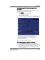
Disk Management ...................................................................... 220
Configuring the Disk management function...................... 221
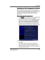
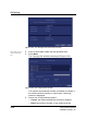
Running the Disk management function........................... 223
Data Backup and Restore................................................. 226
DICOM spooler........................................................................... 232
Starting the DICOM spooler.............................................. 232
Chapter 9
Report
Introduction................................................................................ 236
Creating a report........................................................................ 237
Working with the report function ....................................... 237
To print a report ................................................................ 240
To store a report ............................................................... 240
Retrieving an archived report............................................ 241
Deleting an archived report............................................... 241
Direct report ............................................................................... 242
Creating comments........................................................... 242
Creating pre-defined text inputs........................................ 243
Report designer ......................................................................... 244
Accessing the Report designer......................................... 244
Report designer overview ................................................. 244
Saving the report template................................................ 257
To exit the Report designer .............................................. 258
Report templates management ................................................ 258
Configuration of the Template selection menu ................. 259
Export/Import of Report templates.................................... 260
Chapter 10
Probes
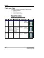
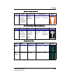
Probe overview .......................................................................... 264
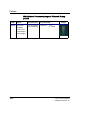
Supported probes ............................................................. 264
Probe labelling .................................................................. 267
Vivid i User’s Manual
2378958-100 Rev. 02
7
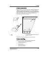
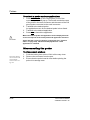
Probe Integration ....................................................................... 269
Connecting the probe ........................................................ 269
Activating the probe........................................................... 269
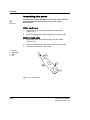
Disconnecting the probe.................................................... 270
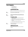
Care and Maintenance ............................................................... 271
Planned maintenance........................................................ 271
Probe safety................................................................................ 276
Electrical hazards .............................................................. 276
Mechanical hazards .......................................................... 276
Biological hazards .............................................................277
Chapter 11
Peripherals
Introduction ................................................................................ 280
Printing........................................................................................ 281
To print an image .............................................................. 281
Specifications for peripherals................................................... 282
Chapter 12
Presets and System setup
Introduction ................................................................................ 284
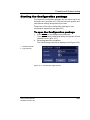
Starting the Configuration package ......................................... 287
To open the Configuration package .................................. 287
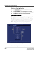
Overview ..................................................................................... 288
Imaging ....................................................................................... 289
The Global setup sheet ..................................................... 289
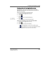
Application......................................................................... 291
Application menu............................................................... 294
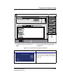
Measure Text .............................................................................. 296
The measurement menu sheet ......................................... 296
The Advanced sheet .................................................................. 302
Parameter configuration: ................................................... 302
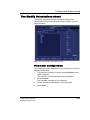
The Modify Calculations sheet ................................................. 303
Parameter configuration: ................................................... 303
Report.......................................................................................... 304
The Comment texts sheet ................................................. 306
8
Vivid i User’s Manual
2378958-100 Rev. 02
Connectivity ............................................................................... 309
Tools ................................................................................. 320
Formats............................................................................. 321
System........................................................................................ 327
The system settings.......................................................... 327
About .......................................................................................... 329
Administration ........................................................................... 330
Chapter 13
User maintenance
System Care and Maintenance................................................. 336
Inspecting the system ....................................................... 336
Cleaning the unit............................................................... 337
Prevention of static electricity interference ....................... 339
System self-test ......................................................................... 341
System malfunction .......................................................... 341
Chapter 14
Safety
Introduction................................................................................ 345
Owner responsibility ................................................................. 346
Important safety considerations .............................................. 347
Notice against user modification....................................... 347
Regulatory information ............................................................. 348
Standards used................................................................. 348
Device labels.............................................................................. 349
Label Icon Description ...................................................... 349
Classifications ........................................................................... 352
Acoustic output ......................................................................... 353
Definition of the acoustic output parameters .................... 353
Acoustic output and display on the Vivid i ........................ 353
ALARA .............................................................................. 354
Safety statement............................................................... 355
System controls affecting acoustic output ........................ 355
Patient safety ............................................................................. 357
Patient identification.......................................................... 357
Vivid i User’s Manual
2378958-100 Rev. 02
9
Diagnostic information....................................................... 357
Personnel and equipment safety.............................................. 359
Explosion hazard............................................................... 359
Electrical hazard................................................................ 359
Biological hazard ............................................................... 360
Pacemaker hazard ............................................................ 360
Electrical safety.......................................................................... 361
Device classifications ........................................................ 361
Internally connected peripheral devices ............................ 361
Internally connected battery .............................................. 361
External Connection of other peripheral devices............... 361
Allergic reactions to latex-containing medical devices ......... 362
Electromagnetic Compatibility (EMC) ...................................... 363
Environmental protection.......................................................... 365
System disposal ................................................................ 365
10
Vivid i User’s Manual
2378958-100 Rev. 02
Introduction
Introduction
The Vivid i ultrasound unit is a compact, high performance
portable digital ultrasound imaging system.
The system provides image generation in 2D (B) Mode, Color
Doppler, Power Doppler (Angio), M-Mode, Color M-Mode, PW
and CW Doppler spectra, Tissue-Doppler imaging (TDI) and
LVO Contrast option applications.
The fully digital architecture of the Vivid i unit allows optimal
usage of all scanning modes and probe types, throughout the
full spectrum of operating frequencies.
Attention
Read and understand all instructions in the User's Manual
before attempting to use the Vivid i ultrasound unit. Keep the
manual with the equipment at all time. Periodically review the
procedures for operation and safety precautions.
For USA only:
CAUTION
United States law restricts this device to sale or use by, or on the
order of a physician.
Safety
All information in Chapter 14, "Safety" on page 343, should
be read and understood before operating the Vivid i
ultrasound unit.
Interference caution
Use of devices that transmit radio waves near the unit could
cause it to malfunction.
CAUTION
Devices not to be used near this equipment:
Devices which intrinsically transmit radio waves such as
cellular phones, radio transceivers, mobile radio transmitters,
Vivid i User’s Manual
2378958-100 Rev. 02
1
Introduction
radio-controlled toys, and so on, should not be operated near
the unit.
Medical staff in charge of the unit are required to instruct
technicians, patients, and other people who may be around the
unit, to fully comply with the above recommendations.
Indications for use
The Vivid i ultrasound unit is intended for the following
applications:
•
Abdominal
•
Cardiac
•
Small Organ
•
Pediatric
•
Fetal
•
Transesophageal
•
Peripheral Vascular
•
Neonatal
•
Adult Cephalic
Contraindications
The Vivid i ultrasound unit is not intended for ophthalmic use or
any use causing the acoustic beam to pass through the eye.
2
Vivid i User’s Manual
2378958-100 Rev. 02
Introduction
Manual contents
The Vivid i User's Manual is organized to provide the
information needed to start scanning immediately.
The safety instruction must be reviewed before operation of the
unit.
CAUTION
Finding information
Table of Contents, lists the main topics and their location.
Headers and Footers, give the chapter name and page
number.
Index, provides an alphabetical and contextual list of topics.
Vivid i User’s Manual
2378958-100 Rev. 02
3
Introduction
Conventions used in this manual
2-column layout, the right column contains the main text. The
left column contains notes, hints and warnings texts.
Keys and button, on the control panel are indicated by over
and underlined text (ex. 2D refers to the 2D mode key)
Bold type, describes button names on the screen.
Italic type: describes program windows, screens and dialogue
boxes.
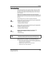
Icons, highlight safety issues as follow:
DANGER
Indicates that a specific hazard exists that, given inappropriate
conditions or actions, will cause:
• Severe or fatal personal injury
• Substantial property damage
WARNING
Indicates that a specific hazard exists that, given inappropriate
conditions or actions, will cause:
• Severe personal injury
• Substantial property damage
CAUTION
4
Indicates that a potential hazard may exist that, given
inappropriate conditions or actions, can cause:
• Minor injury
• Property damage
Vivid i User’s Manual
2378958-100 Rev. 02
Introduction
Contact information
If additional information or assistance is needed, please
contact the local distributor or the appropriate support resource
listed bellow:
Europe
GE Ultraschall KG
Tel: 0130 81 6370
Deutschland GmbH & Co.
Tel: (49)(0) 212-28-02-208
Beethovenstraße 239
Postfach 11 05 60
D-42655 Solingen
USA
GE Medical Systems
Tel: (1) 800-437-1171
Ultrasound Service Engineering
Fax: (1) 414-647-4090
4855 W. Electric Avenue
Milwaukee, WI 53219
On-line Applications Support
Tel: (1) 800-682-5327
or (262) 524-5698
Canada
GE Medical Systems
Tel: (1) 800-664-0732
Ultrasound Service Engineering
4855 W. Electric Avenue
Milwaukee, WI 53219
On-line Applications Support
Tel: (1) 800-682-5327
or (262) 524-5698
Asia
GE Ultrasound Asia
Tel: (65) 291-8528
Service Department Ultrasound
Fax: (65) 272-3997
298 Tiong Gahru Road # 15-01/06
Central Plaza
Singapore 168730
Vivid i User’s Manual
2378958-100 Rev. 02
5
Introduction
Latin and South America
GE Medical Systems
Tel: (1) 305-735-2304
Ultrasound Service Engineering
4855 W. Electric Avenue
Milwaukee, WI 53219
On-line Applications Support
Tel: (1) 800-682-5327
or (262) 524-5698
Brazil
GE Ultrasound
Tel: (55.11) 887-8099
Rua Tomas Carvalhal, 711
Fax: (55.11) 887-9948
Paraiso
Cep: 04006-002 - São Paulo, SP
6
Vivid i User’s Manual
2378958-100 Rev. 02
Getting started
Chapter 1
Getting started
• Preparing the unit for use ............................................................ ...... 9
• Site requirements ......................................................................... 9
• Connecting the unit .................................................................... 10
• Switching On/Off ........................................................................ 18
• Moving and transporting the unit ................................................ .... 22
• Moving the unit on a Cart ........................................................... 22
• Transporting the unit .................................................................. 23
• Unit acclimation time .................................................................. 23
• System description ....................................................................... .... 24
• System overview ........................................................................ 24
• Control panel .............................................................................. 25
• The Scanning screen ................................................................. 35
• Connecting and disconnecting probes ....................................... 38
• Adjusting the display monitor ..................................................... 41
• Starting an examination ............................................................... .... 42
• Creating a new Patient record or starting an examination from an
existing patient record ................................................................ 42
• Selecting a Probe and an Application ........................................ 46
Vivid i User’s Manual
2378958-100 Rev. 02
7
Getting started
Introduction
Only qualified physicians or ultrasound sonographers should
perform scans of patients for medical diagnostic reasons.
Request training, if needed.
An authorized GE representative will unpack and install the
unit. Do not attempt to install the unit alone.
The Vivid i does not contain any operator serviceable internal
components. Ensure that authorized personnel do not tamper
with the unit.
Perform regular preventive maintenance. See 'System Care
and Maintenance' for more information.
Maintain a clean environment. Turn OFF, and if possible,
disconnect the system before cleaning the unit. See 'Cleaning
the system' for more information.
Never set liquids on the unit to ensure that liquid does not drip
into the control panel or unit.
WARNING
8
All the warnings in "Important safety considerations" on
page 347, should be read and understood before operating the
unit.
Vivid i User’s Manual
2378958-100 Rev. 02
Getting started
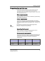
Preparing the unit for use
The Vivid i ultrasound unit must operate within the proper
environment and in accordance with the requirements
described in this section. Before using the system, ensure that
the requirements are met.
Site requirements
Optimal operation of the unit can be obtained by implementing
the following requirements:
Power requirements
The Vivid i ultrasound unit is powered either by its internal
battery or by a separate power supply adaptor unit connected
to a separate power outlet for any range of 100 – 230 VAC, 50–
60 Hz.
Operating the unit with the wrong voltage range causes
damages, voiding the factory warranty.
WARNING
Operating Environment
Ensure that there is sufficient air flow around the Vivid i
ultrasound unit when installed or operated.
Environmental requirements
The Vivid i ultrasound unit requires constant maintenance of its
operational environment. Different temperature and humidity
requirements are specified for operation, storage and
transportation.
Requirement
Temperature
Humidity
Air Pressure
Operational
10–40 °C
30–85%
700–1060 hPa
Storage
-10–60 °C
30–95%
700–1060 hPa
Transport
-10–60 °C
30–95%
700–1060 hPa
Vivid i User’s Manual
2378958-100 Rev. 02
9
Getting started
Electromagnetic interferences
The Vivid i ultrasound unit is approved for use in
hospitals, clinics
and other environmentally qualified
facilities, in terms of
the prevention of radio wave interference. Operation of
the unit in an inappropriate environment can cause
electronic interference to radios and
television sets situated near the medical equipment.
Ensure that the unit is protected from electromagnetic
interferences as follows:
•
Operate the unit at least 4.5 meters (fifteen feet) away from
equipment that emits strong electromagnetic radiation.
•
Shield the unit when operating it in the vicinity of radio
broadcasting equipment, if necessary.
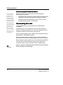
Connecting the unit
A GE-qualified person should perform the initial system
installation.
Connecting the Vivid i ultrasound unit involves preliminary
checks of the power adaptor unit and cord, voltage level and
compliance with electrical safety requirements.
Use only power supply cords, cables and plugs provided by or
designated by GE Medical Systems.
Ensure that the power cord and plug are intact and that the
power plug is the proper hospital-grade type (where required).
When using the mains outlets, the unit should be connected to
a fixed power socket which has the protective grounding
connector. Never use an extension cord or adapter plug.
Failure to provide an adequate earth circuit can cause electrical
shock, resulting in serious injury.
WARNING
10
Vivid i User’s Manual
2378958-100 Rev. 02
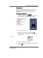
Getting started
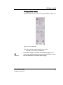
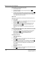
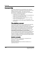
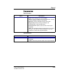
Voltage level check
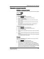
Check the label on the Vivid i’s AC power adaptor (Figure 1-1).
Figure 1-1: The rating label
Check the voltage range indicated on the label:
•
100–240 V, 1.08–0.45 A, 50/60 Hz
WARNING
If the mains supply is not within the specified range, do not
connect the unit to the power source. Contact the dealer to have
the unit adjusted to the specific mains supply.
Vivid i User’s Manual
2378958-100 Rev. 02
11
Getting started
Connecting to the electrical outlet
WARNING
The unit’s power must be supplied from a separate, properly
rated outlet to avoid risk of fire. Refer to "Power requirements"
on page 9 for rating information.
The power cord should not, under any circumstances, be altered
to a configuration rated less than that specified for the current.
Do not use an extension cord or adapter plug.
1.
2.
3.
Connect the AC power adaptor output plug into the
appropriate socket on the rear of the Vivid i.
Ensure that the wall outlet is of appropriate type.
Secure the power plug in the wall outlet.
AC Adapter
Use only the special AC Power adapter for Vivid i, specifically
designed and approved by GE.
CAUTION
Be sure that nothing rests on the AC adapter’s power cable and
that the cable is not located where it can be tripped over or
stepped on.
Place the AC power adapter in a ventilated area, such as a desk,
when you use it to run the Vivid i.
Do not cover the AC power adapter with paper or other items
that will reduce cooling; do not use the AC power adapter inside
a carrying case.
Battery
The lithium ion battery provides power when an AC power
source is not available. A battery in the battery bay is standard
with the Vivid i. You can expect one hour of battery life with a
single fully charged battery. Lithium ion batteries last longer
than conventional batteries and do not require replacement as
often.
Note: The battery is
designed to work
with Vivid i systems only. Only use
the batteries authorized by GE.
12
The lithium ion technology used in the system’s battery is
significantly less hazardous to the environment than the lithium
metal technology used in some other batteries (such a watch
batteries). Used batteries should not be placed with common
household waste products. Contact local authorities for the
location of a chemical waste collection program nearest you.
Vivid i User’s Manual
2378958-100 Rev. 02
Getting started
The battery has a safety device. Do not disassemble or alter it.
WARNING
Charge the batteries only when the ambient temperature is
between 0° and 65° C (32° and 149° F) and discharge the batteries
between -10° and 55° C (14° and 131° F).
Do not short-circuit the battery by directly connecting the battery
terminals with metal objects.
Do not heat the battery or discard it in a fire.
Do not expose the battery to temperature over 60° C (140° F).
Keep it away from fire and other heat sources.
Do not charge the battery near a heat source, e.g. fire or heaters.
Do not leave the battery in direct sunlight.
Do not pierce the battery with a sharp object, hit it, or step on it.
Do not use a damaged battery.
Do not solder a battery.
Do not connect the battery to an electrical outlet.
If the Vivid i is not being used on a monthly basis, the battery
needs to be removed during lengthy non-use period.
WARNING
CAUTION
To avoid the battery bursting, igniting, or fumes from the battery
causing equipment damage, observe the following precautions:
• Do not immerse the battery in water or allow it to get wet.
• Do not put the battery into a microwave oven or pressurized
container.
• If the battery leaks or emits an odor, remove it from all possible
flammable sources.
• If the battery emits an odor or heat, is deformed or discolored,
or in a way appears abnormal during use, recharging or
storage, immediately remove it and stop using it. If you have
any questions about the battery, consult GE or your local
representative.
Storage of battery pack:
• Short term (less than one month): 0° C (32°F) - 50° C (122°F)
• Long term (more than three months): 10° C (50° F) - 35° C (95°F).
• Use only GE recognized batteries.
Vivid i User’s Manual
2378958-100 Rev. 02
13
Getting started
Using the Vivid i with a Battery
The Vivid i can be powered by two different power sources in
three different ways:
1. AC power adapter only (without the battery)
2. AC power adapter and a battery (Battery being charged in
the system)
3. Battery only (without power from the AC power adaptor)
The user has indications of the states of the power sources
both by a graphic icon on bottom of display (while system is
operating), and by a pair of LED lights which operate even
while the system is OFF.
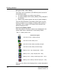
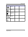
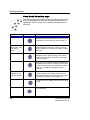
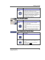
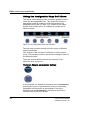
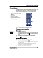
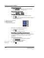
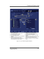
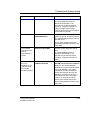
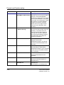
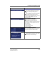
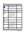
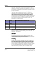
View Current Battery Status
When the system is running, a status icon is displayed in the
system Status bar to indicate the current battery status.
Table 1-1: Battery status icons
Icon
Status Description
AC Power is ON; no battery present
AC Power is ON; battery is full
AC Power is ON; battery is partially charged
AC Power is ON; battery is almost empty
Battery in use - fully charged (80% - 100%)
Battery in use - partly charged (25% - 80%)
Battery in use - battery is discharged (10% - 25%)
Battery in use -battery is almost empty (0% - 10%)
When the user clicks on the displayed icon, a status description
appears.
14
Vivid i User’s Manual
2378958-100 Rev. 02
Getting started
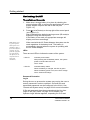
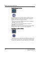
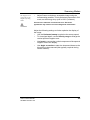
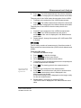
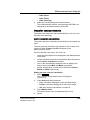
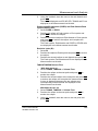
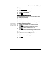
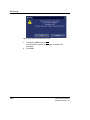
Battery Power Low Warning
If the battery is in use and the battery power is 10% or less, a
warning message appears to warn the user that the battery
power is low and that it needs to be charged.
Note: When the battery power is low
and the user cannot
charge the battery
in time, the system
automatically shuts
down in 2 minutes.
This protects the
whole system. You
need to save all unsaved data before
the system shuts
down or you may
lose useful information.
Figure 1-2: Low Battery Power Warning
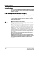
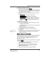
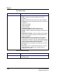
Peripherals/Accessory connection
Refer to page 279
for further information on peripherals.
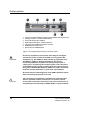
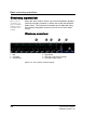
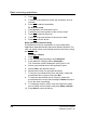
The external Peripherals / accessories connectors are situated
on the rear side of the unit See Figure 1-3.
Peripherals/Accessory Connector Panel
Vivid i peripherals and accessories can be properly connected
using the rear connector panel.
Use only approved peripherals, accessories or probes.
CAUTION
DO NOT connect any accessories or probes without approval by GE
Vivid i User’s Manual
2378958-100 Rev. 02
15
Getting started
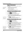
1. Two interchangeable USB ports (digital printer, CD-RW and other peripherals
2. Docking connector - for future external devices
3. Port for DC IN (AC Power Adapter)
4. SVGA Output (VCR option or External monitor)
5. LAN 10/100 Base-TX Ethernet network connector
6. PCMCIA port for wireless card
7. Ejection lever for PCMCIA device
Figure 1-3: Peripherals/Accessory Connector Panel
WARNING
Accessory equipment connected to the analogue and digital
interfaces must be certified according to the respective IEC
standards (e.g. IEC 60950 for data processing equipment and
IEC 60601-1 (1988) for medical equipment). Any person
connecting additional equipment to the signal input part or
output part is configuring the medical system, and is therefore
responsible that the system complies with the requirements of
the system standard IEC 60601-1-1 (2000). If in doubt, consult the
technical service department or your local representative.
Do not touch the conducting parts of the USB or Ethernet cables
when connecting equipment to the unit.
CAUTION
16
The connection of equipment or transmission networks other
than as specified in these instructions can result in electric
shock hazard. Alternate connections will require verification of
compatibility and conformity to IEC/EN 60601-1-1 by the installer.
Vivid i User’s Manual
2378958-100 Rev. 02
Getting started
Socket
Signal type
Device type
SVGA Out
SVGA output
RGB high
resolution video
Computer monitor
USB
Universal serial
bus x2
Ethernet
10/100 Base-TX
Ethernet IEEE
8023
Network device
Docking Bay
Connector
Docking bay
connector
AC Adapter
Input
DC voltage from
AC adapter unit
Note
Network device
Table 1-2: Contents of the Rear Panel
Vivid i User’s Manual
2378958-100 Rev. 02
17
Getting started
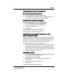
Switching On/Off
To switch on the unit:
Note: When turning ON a system
while system is in
standby, it takes a
few seconds before it
responds. Do not
push the on/off button again during
this period (A second push will initiate a full
shutdown).
1.
Make sure a charge battery is in place by checking the
power indicator LED, or connect the appropriate AC power
supply adapter output to the rear of the unit (see
Figure 1-3).
2.
Press (on/off button) on the top right of the control panel
(see Figure 1-6).
After initialization the default scanning screen (2D mode) is
displayed, using the active probe.
If the battery is too weak, an appropriate message will
display on screen accordingly.
When used with the AC Power Adaptor, the system can be
used regardless of the battery level. The battery is
automatically charged when the system is operating with
the AC Power Adaptor.
LEDs
There are two LEDs to indicate the status of the system.
• LED #1
Indicates power status.
After pressing the On/Standby switch, the system
power is ON and this LED is lit.
Color: Green
• LED #2
Indicates battery status.
When the battery is charged, the LED is green.
When the battery power is low, the LED is orange.
Color: Green and Orange
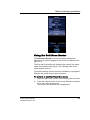
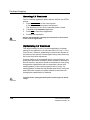
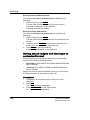
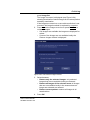
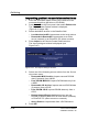
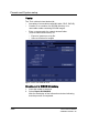
Password Protection
Log In
During the turn-on process the system may require the user to
enter a password in order to operate it. Personal IDs and
associated passwords can be configured in the Vivid i. See
"Presets and System setup" on page 283 for more information.
If IDs and passwords have been entered and the Use Auto
Logon is Off (see "Users" on page 331 for details), the
Operator Login Window appears, requesting for an ID and
18
Vivid i User’s Manual
2378958-100 Rev. 02
Getting started
password when Power up sequence is completed, or when it is
required.
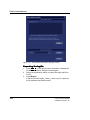
1. Operator:
Select the relevant Operator name.
2. Password
Enter the Operator’s password.
3. Emergency
Data stored for the duration of the current examination only.
4. Log on:
Select type of Log on (for example, Standard logon).
5. Cancel
Cancel Log on.
Figure 1-4: Operator Login Window
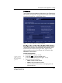
Switching off the unit
When the Vivid i is switched off, the system performs an
automatic shutdown sequence. The unit can be switched off
into two states.
•
Standby mode: most of the system is powered down, but
a certain portion of the unit remains energized. The standby
mode allows a shorter reboot time when the system is used
on a daily basis or moved from one place to another.
•
Full shutdown: the entire system is shut down. Full
shutdown is recommended if the system is not intended to
be used for a whole day or longer. It is recommended to
perform a full shutdown at least once a week.
After switching off
the system, wait at
least ten seconds before turning it on
again.
Full shutdown
1. Press
(on/off button) on the top left of the control panel.
The Exit dialogue window is displayed.
Vivid i User’s Manual
2378958-100 Rev. 02
19
Getting started
Figure 1-5: The Exit dialogue window
In case of total lockup of the system,
hold the on/off button down a few seconds to turn the
system off.
In case of total lockup of the system,
hold the on/off button down a few seconds to turn the
system off.
2.
Select Shutdown.
The shutdown process takes a few seconds and is
completed when the control panel illumination is turned off.
Standby mode
1. Press
(on/off button) on the top left of the control panel.
The Exit dialogue window is displayed (Figure 1-5).
2. Select Standby.
The system enters Standby mode.
The system remains in Standby mode for approximately
XX hours using the internal battery.
Note: When the system is operating, if the power cable is
removed from the wall outlet or the Power Adaptor is
disconnected from the Vivid i, the system will continue to
operate using the internal battery. When battery power is
reduced below a certain level the system automatically
shuts down into Standby mode.
Eventually, if left for a long time, the system will switch
from Standby mode to full shut-down.
20
Vivid i User’s Manual
2378958-100 Rev. 02
Getting started
Turning on the system at the new location
1.
In order to maintain the battery charge it is recommended
to plug the AC cable into a proper power outlet. If a charged
battery is in place, the power plug does not need to be
plugged into the wall outlet.
2.
3.
Press
(on/off button) (Figure 1-6).
If the system does not turn ON, the battery may be drained.
In this case, plug the power plug into the wall outlet and try
again.
When turning on a system in standby it takes a few seconds
before it responds. Do not push the on/off button again during
this period (A second push will initiate a full shutdown).
The system can be used regardless of the battery level. The
battery is automatically charged when the system is plugged to
the wall outlet. It takes about 2 hours to charge a completely
discharged battery. This may gradually change as battery ages
with time.
Vivid i User’s Manual
2378958-100 Rev. 02
21
Getting started
Moving and transporting the unit
Moving the unit on a Cart
To prepare the unit to be moved
1.
Note the marks on
each cable to reconnect them later.
2.
3.
4.
5.
6.
Turn the system OFF either in Standby or Full Shutdown
mode, and remove the AC power plug from the wall outlet.
Fold the LCD screen to the fully closed position.
Disconnect all cables linking the system or peripherals to
any off-board peripheral devices and network.
Secure the unit’s power cable on the Cart.
Place all probes securely on the cart. Ensure that the probe
cables do not protrude from the unit or interfere with the
wheels.
Ensure that no loose items are left on the unit
To ensure safety while moving the unit
1.
Ensure that the LCD screen is in the locked position.
2.
Proceed cautiously when crossing door or elevator
thresholds. Do not attempt to move the unit using cables or
probe connectors. Take extra care while moving the unit on
inclines.
Ensure that the unit does not strike the walls or door
frames.
Ensure the pathway is clear.
Move the unit slowly and carefully.
3.
4.
5.
Avoid ramps that are steeper than 10 degrees.
CAUTION
22
Vivid i User’s Manual
2378958-100 Rev. 02
Getting started
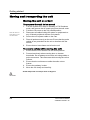
Transporting the unit
Take extra care when transporting the unit by vehicle. In
addition to the moving precautions listed on page 22, follow the
procedure described below.
1. Disconnect all probes and secure them in their boxes.
2. Remove the Vivid i system from the Cart and place it in the
travel bag supplied by GE, or an equivalent suitable travel
bag.
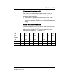
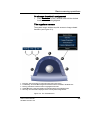
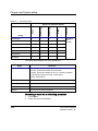
Unit acclimation time
Following transport the unit may be very cold or hot. Allow the
unit to acclimate before being switched on. Acclimation will
take one hour for each 2.5 oC increment when the unit’s
temperature is below 10 oC or above 40 oC.
oC
0
2.5
5
7.5
10
35
40
42.5
oF
32
36.5
41
45.5
50
95
104
108.5
Hours
4
3
2
1
0
0
2
3
oC
45
47.5
50
52.5
55
57.5
60
oF
113
117.5
122
126.5
131
135.5
140
Hours
4
5
6
7
8
9
10
Vivid i User’s Manual
2378958-100 Rev. 02
23
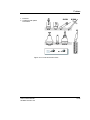
Getting started
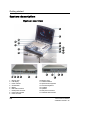
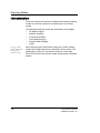
System description
System overview
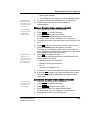
1. Display latch
10. Monitor hinge
2. LCD display
11. Softmenu buttons
3. Power indicator
12. Alpha-numeric keyboard
4. On/Off button
13. Functional keyboard
5. Battery
14. Trackball
6. ECG cable connector
15. Speakers
7. Pedoff probe connector
16. Rear panel connectors
8. Probe locking handle
17. Anti-theft cable insertion
9. Probe connector
24
Vivid i User’s Manual
2378958-100 Rev. 02
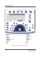
Getting started
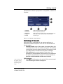
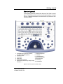
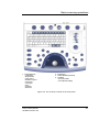
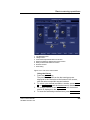
Control panel
The following pictures illustrate the layout of the Vivid i control
panel. The buttons and controls are grouped together for ease
of use. A detailed description of the buttons is provided on the
following pages.
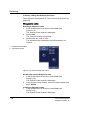
1. Assignable keys (soft-menu elements;
part of the Extended keyboard)
7. Extended keyboard
2. Soft menu rocker
9. Trackball buttons
3. TGC sliders
10. Mode selection keys
4. GAIN rotary
11. Navigation keys
8. Trackball
5. Alphanumeric keyboard
12. Freeze keys
6. Alphanumeric function keys: (Help, Config, 13. On/Off button
Annotate ...)
Figure 1-6: The Vivid i Control Panel
Vivid i User’s Manual
2378958-100 Rev. 02
25
Getting started
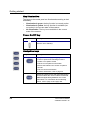
Key illumination
The keys on the control panel are illuminated according to their
availability:
•
Illumination in green: the key function is currently active.
•
Illumination in yellow: the key function is available (but
not active) in the current state of the scanner.
•
No illumination: The key is not available in the current
state of the scanner.
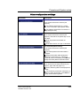
Power On/Off key
Key
Description
Turns the unit ON and OFF.
Sets the unit to Standby.
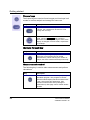
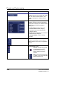
Navigation keys
Key
Description
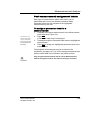
Displays the Archiving opening page. Enables
the user to perform the following functions:
• Create a new patient record
• Edit the current patient’s information
• Browse the Patient List to search for patient
records
• End the current examination
For further information, refer to page 42.
Displays the Select Probe and Application dialog
box that enables the users to select the desired
probe and application preset for the current
examination. For information about selecting
probes, refer to page 46 and page 263.
26
Vivid i User’s Manual
2378958-100 Rev. 02
Getting started
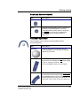
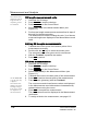
Key
Description
Brings the scanner into the Image review mode,
that enables the user to select images from the
clipboard for analysis, activate the image
browser or enter the Image Review screen
where bigger previews of the images are shown
for image selection. Refer to page 181 for details
on the review of images.
Displays the Measurement worksheet where the
user may edit or delete measurements, change
averaging etc. Refer to page 147 for details on
how to operate the worksheet.
Vivid i User’s Manual
2378958-100 Rev. 02
27
Getting started
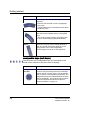
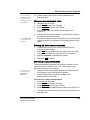
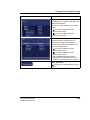
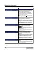
Scan Mode Selection keys
The following keys are used to select the required scan mode,
and to select additional tools that enhance the application’s
capabilities. Refer to page 75 for detailed information about
scanning.
Key
Description
Displays the 2D live acquisition mode that is the
default scanning screen for the unit. For further
information on 2D scanning, refer to page 77.
M-Mode can be
added from a 2D
scan also in
replay.
Displays the M-Mode examination screen and
enables M-Mode functions. Used for viewing
motion patterns. For further information, refer to
page 83.
Color
Displays the examination screen in Color Flow
Mapping mode. Used to display color-coded
blood flow information. For further information,
refer to page 88.
Displays the examination screen in Pulsed Wave
Doppler mode. Used for displaying the Doppler
spectrum of blood flow at a selected part of the
anatomy. For further information, refer to
page 94.
CW mode is not
available on all
scanning probes.
Displays the examination screen in Continuous
Wave Doppler mode. Allows examination of
blood flow data all along the Doppler CW cursor.
For further information, refer to page 94.
Toggles the cursor display on/off in 2D scanning
mode.
For future use
28
Vivid i User’s Manual
2378958-100 Rev. 02
Getting started
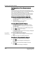
Basic Mode Parameter Adjustment Controls
The following controls are used to modify and adjust the unit’s
display to best suit the user’s requirements, such as color, gain,
zoom and image depth, according to the mode being operated
by the user.
Controls
Description
Gain rotary
Controls the total gain of the active mode: gray
scale images in 2D Mode, or the total gain of
other activated modes, such as, M-Mode, Color,
PW, or CW Doppler mode.
Active mode
In combined mode, switches between the mode
specific assignable controls and total-gain of the
currently used modes.
TGC
Six sliding keys that compensate for
depth-related attenuation in an image. The upper
slider corresponds to the smallest depth.
Depth
Controls the displayed depth of tissue scan. Has
no effect in replay.
Changes the angle of the cursor on linear
probes. The steering angles are fixed for each
linear probe. This key has no effect with sector
imaging probes.
Vivid i User’s Manual
2378958-100 Rev. 02
29
Getting started
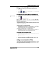
Freeze keys
The freeze keys are used to freeze images and cine loops in all
modes for on-line analysis and storage for future use.
Key
Description
Stops or restarts all data acquisition. When scan
is frozen, the Trackball can be used to scroll
through the cine loop.
Activates or freezes 2D mode. In simultaneous
mode, pressing 2D FREEZE will activate or
deactivate the 2D image, leaving the other mode
display unchanged. In freeze mode, stops/starts
the cineloop.
Multiple Format Key
Key
Description
Enables multiple image display windows in
which two or four images can be viewed
simultaneously. When reducing the number of
images, the active window will always been kept.
Measurement control
The following key is used to take measurements and perform
calculations.
Key
Description
Activates the Measurement & Analysis (M&A)
calculation program. This program is context
sensitive and will display relevant measurements
to the current mode and application. Also
activates measurement tools (unassigned
measurement). See page 109 for further details
on M&A.
30
Vivid i User’s Manual
2378958-100 Rev. 02
Getting started
Print and Record Control
Key
Description
Record
For future use.
Print
Prints the current imaging screen content to a
selected (configurable) printer. For more
information about printing. Refer to page 281.
The PRINT key can also be configured for
alternative storing of images (Refer to
page 318.).
Trackball operation
The Trackball area consists of the trackball and five
surrounding keys.
Key
Description
Trackball
Used for navigation and together with the
surrounding keys, to move, select or activate
objects on the screen.
Zoom
Controls image magnification. Press to activate
Zoom mode; use trackball and SET button toggle
to pan or change zoom factor.
Zoom is available in both Live and Replay.
Trackball
Vivid i User’s Manual
2378958-100 Rev. 02
Controls the trackball assignments between the
mode-specific options. By pressing TRACKBALL,
the trackball function will cycle through the
possible assignments, which are indicated in the
lower right corner of the screen (see page 54).
31
Getting started
Key
Description
Set
Depending on the situation (see Figure 2-3,
page 55):
• Performs the selected control or highlighted
menu item.
• Toggles between the Trackball functions within
the active group.
Update Menu
In Freeze, activates menu with additional options
and controls not available from the assignable
keys.
In live mode, toggles between 2D imaging and
live time-motion imaging (Doppler/M-Mode).
Store
Stores the currently active imaging window to
disk. The stored information depends on the
configuration of the current application.
Stored images are shown on the clipboard.
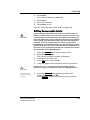
Assignable keys (soft keys)
The functions of the assignable keys vary according to the
mode and/or module in which the user is working.
32
Key
Description
Assignable
Circular
Three 4-way knobs, whose mode-specific
functions vary according to the scan mode and
position that is currently active. This assignable
knob is used to control variable parameters. The
assigned functions are indicated above the knob
on the LCD display. The mode-specific functions
for these knobs are described in Chapter 3,
"Scanning Modes" on page 75.
Vivid i User’s Manual
2378958-100 Rev. 02
Getting started
Key
Description
Assignable
Buttons
Four assignable buttons, whose mode-specific
functions vary according to the scan mode and
position that is currently active. These
assignable buttons are used as on/off toggles for
different controls on the menu. The assigned
functions are indicated above the button on the
LCD display. The mode-specific functions for
these buttons are described in Chapter 3,
"Scanning Modes" on page 75.
The soft menu rocker
Key
Description
Soft Menu
Rocker
A 4-way rocker used to access mode-specific
menus, select a menu option and adjust
option-related values.
• The vertical arrows are used to select the menu
options.
• The horizontal arrows are used to adjust the
values.
The mode-specific menus are described in
Chapter 3, "Scanning Modes" on page 75.
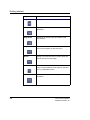
The Alphanumeric Function keys
Key
Description
Help
Displays the on-line version of the user manual.
Config/Diag
Displays the configuration dialog box, allowing
user configuration of various settings on the
scanner.
Diagnostics of the system is activated by
pressing Shift > CONFIG.
Vivid i User’s Manual
2378958-100 Rev. 02
33
Getting started
34
Key
Description
Report
Displays the examination report.
Bodymark
Displays the available body marks for the current
application.
Page Erase
Erases all previously-typed annotations (and
body marks).
Physio
Provides access to controls for ECG trace. The
ECG controls appear on the soft-menu.
Arrow
Displays an arrow that can be used to point at a
specific structure in the image.
Text
Enables text annotation to be inserted on the
image. The annotations can be typed or selected
from a (configurable) menu.
Delete
Can be used to delete text during text
annotation.
Vivid i User’s Manual
2378958-100 Rev. 02
Getting started
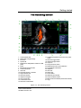
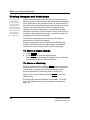
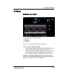
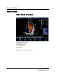
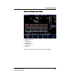
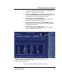
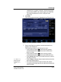
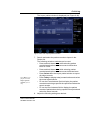
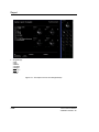
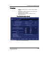
The Scanning screen
1. Current patient data
2. Date & time of original image
17. Trackball assignment, Service and iLinq, Caps
on/off
3. Institution
18. Soft menu toggle button
4. Operator ID
19. Clipboard image number
5. Application & Temperature indicator for TEE
probe
20. Loop icon
6. Probe
22. Watermark area for screen calibration
7. Mechanical & Thermal Index
23. Prompt/Status information
8. Current date & time
24. Clipboard
9. Heart rate
25. Heart rate
10. Parameter window - all modes
26. Depth scale
11. Greyscale/Color bar
27. Focus marker
12. Soft menu window
28. TEE Scan plan indicator
13. Clipboard navigator
29. Probe orientation marker
14. Cine progress bar
30. Measurement result table (measurement mode)
15. Current menu name
31. Logo
21. 4-way soft menu control
16. Soft menu control button
Figure 1-7: The scanning screen
Vivid i User’s Manual
2378958-100 Rev. 02
35
Getting started
The scanning screen is divided in several areas as follows:
The title bar
From the left:
The patient information displayed on
the Title bar is configurable (see
page 290).
Patient Information
Displays the information that uniquely identifies the patient,
such as patient name, identification number and birth date.
This information is entered in the New patient window, as
described on page 42.
Institution name
The institution name is entered from the configuration package.
See page 327 for more detailed information.
Operator ID
Identification code of the operator. See page 331 for creating
operator ID’s.
Date and time
Displays the current date and time or for a retrieved image, the
date and time at which it was stored.
Probe and Application
Displays the currently selected probe and application or for
retrieved image the probe and application that were used. See
page 46 and page 269 for further information on how to select
probe and application.
Live scanning related information
Displays, if available, the current values for
•
Mechanical Index (MI), for the current active image
•
Thermal Index (TI), for the current active image
•
probe temperature (for TE probe)
•
Heart rate (HR)
Archive Information
Displays the currently selected patient and image archives.
36
Vivid i User’s Manual
2378958-100 Rev. 02
Getting started
Parameters window
Displays scan mode or application specific parameters. In
scanning mode the parameters for the active mode are
highlighted. This window also displays zoom information and
image groups in image browser.
Soft menu window
Displays the mode specific controls operated from the 4-way
rocker on the control panel. The mode-specific menus are
described in Chapter 3, "Scanning Modes" on page 75. For
operating procedure of the 4-way rocker see page 53.
Clipboard
Displays the thumbnail images representing the acquired data
during the current examination.
The status bar
Consists of four information fields as follows:
Service iLinq button (wrench icon)
Enable access to the GE Medical Systems on-line service
center.
Connectivity status icon
Displays the network status: Connected or disconnected.
Power & Battery status
Displays the power status. Amount of battery charge and if AC
adapter is connected (see page 14)
Prompt/status field
Displays system messages or prompts the user for actions.
Trackball assignments fields
Displays the available assignments of the trackball. The current
assignment is highlighted.
The acquisition window
Displays the ultrasound image with relevant indicators such as
depth, focus, probe orientation marker, physiological
traces...etc.
Vivid i User’s Manual
2378958-100 Rev. 02
37
Getting started
Connecting and disconnecting probes
Probes can be connected or changed at any time, regardless of
whether the system is powered ON or OFF.
Handle the probes gently while connecting and disconnecting.
CAUTION
WARNING
Do NOT touch the patient and any of the connectors on the
ultrasound unit simultaneously, including ultrasound probe
connectors.
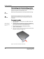
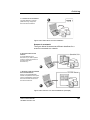
To connect a probe:
1.
Probes can be connected or changed
any time while the
unit is on.
2.
3.
4.
Place the probe’s carrying case on a stable surface and
open the case.
Carefully remove the probe and unwrap the probe cord.
DO NOT allow the probe head to hang freely. impact to the
probe head could result in irreparable damage.
Press the probe connector locking lever (refer to
Figure 1-9) downwards.
Align the connector with the probe port and carefully push
into place, as shown in Figure 1-8.
Figure 1-8: Probe Connection to the Vivid i
38
Vivid i User’s Manual
2378958-100 Rev. 02
Getting started
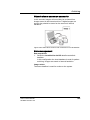
5.
Lift the connector locking lever (see Figure 1-9) upwards to
the full horizontal position to lock in place.
Figure 1-9: Probe Connection Locking Lever
6.
CAUTION
Carefully position the probe cord so that it is free to move
and is not resting on the floor.
When the probe is connected, it is automatically activated.
Fault conditions can result in electric shock hazard. Do not touch
the surface of probe connectors which are exposed when the
probe is removed. Do not touch the patient when connecting or
disconnection a probe.
Cable Handling
Take the following precaution with probe cables:
•
Do not bend the cable acutely.
Deactivating the Probe
Press the FREEZE key to deactivate the probe. When
deactivating the probe, the probe is automatically placed in
Standby mode.
Disconnecting the Probe
Probes can be disconnected at any time. It is recommended
that the probe should not be active when being disconnected.
Vivid i User’s Manual
2378958-100 Rev. 02
39
Getting started
To disconnect a probe:
1. Freeze the image by pressing FREEZE.
2. Press the connector locking lever down to unlock the
connector.
3. Pull the probe and connector straight out of the probe port.
4. Carefully slide the probe and connector away form the
probe port and around the right side of the keyboard.
5. Ensure the cable is free.
6. Be sure that the probe head is clean before placing the
probe in its storage case.
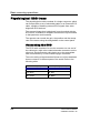
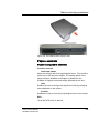
Transporting Probes
When transporting a probe a long distance, store it in its
carrying case.
Storing Probes
It is recommended that all probes be stored in the carrying
case provided.
•
First place the probe connector into the carrying case
•
Carefully wind the cable into the carrying case.
•
Carefully place the probe head into the carrying case.
DO NOT use excessive force or impact the probe face.
40
Vivid i User’s Manual
2378958-100 Rev. 02
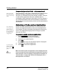
Getting started
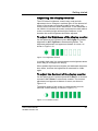
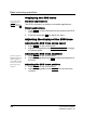
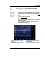
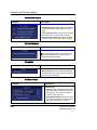
Adjusting the display monitor
The LCD screen brightness controls may need periodic
adjustment due to changes in ambient light. On the bottom left
corner of the screen you should be able to see a dark, yet
visible, letter V which is called "Watermark". If the watermark is
not visible it is because the screen is adjusted too dark relative
to the surrounding bright ambient light conditions. In this
situation the screen brightness should be adjusted.
To adjust the Brightness of the display monitor
On the alphanumeric keyboard press ALT+PgUp to increase
brightness or ALT+PgDown to decrease brightness. The
brightness adjustment tool appears at bottom of screen, as
shown in Figure 1-10.
Figure 1-10: Brightness Control
In a totally dark room it is recommended to set brightness down
all the way (all rectangles are empty).
When ambient light becomes brighter and watermark becomes
less visible, increase the brightness till watermark is visible
again
To adjust the Contrast of the display monitor
On the alphanumeric keyboard press ALT+Steer-> to increase
contrast or ALT+Steer<- to decrease contrast. The contrast
adjustment tool appears at bottom of screen, as shown in
Figure 1-11.
The default setting of the screen is recommended to be at
maximal contrast setting, as shown in Figure 1-11.
Figure 1-11: Contrast Control
Vivid i User’s Manual
2378958-100 Rev. 02
41
Getting started
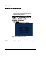
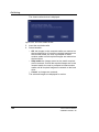
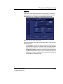
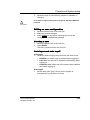
Starting an examination
Beginning an exam consists of three steps:
•
Creating a new patient record or starting a new examination
from an existing patient record (see below)
•
Selecting Probe and Application (see page 46)
•
Start scanning (see page 46)
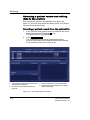
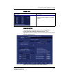
Creating a new Patient record or
starting an examination from an
existing patient record
Starting an examination
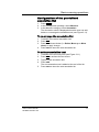
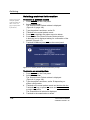
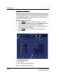
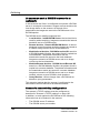
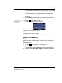
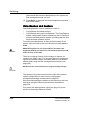
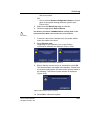
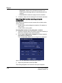
1.
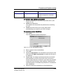
Press PATIENT.
The Patient Handling screen is displayed.
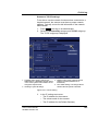
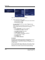
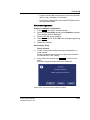
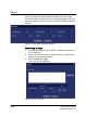
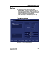
Figure 1-12: The Patient Handling Screen
2.
To create an operator ID, see
page 331.
42
Press CREATE NEW PATIENT.
If the unit is password protected a Log In window will
appear asking for operator ID and password (as explained
in Figure 1-13).
Vivid i User’s Manual
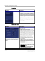
2378958-100 Rev. 02
Getting started
1. Data stored only for
the duration of the
current examination
2. Select the operator
Figure 1-13: The Operator login window
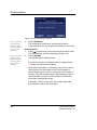
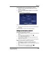
3.
4.
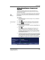
Press Log on when completed.
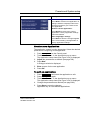
The Search/Create Patient window is displayed (see
Figure 1-14).
Type the patient Last Name, and/or ID.
Do NOT use '\' or '^' in patient information fields, as these
characters might cause problems with some DICOM devices.
CAUTION
The unit can be configured to automatically generate a
patient ID (see
page 321).
To restrain the
search to special
category of patient
record, press More
and use the searching filters.
The automatic
search tool displaying matching patient information in
the Patient list can
be turned off (see
page 321).
When default configured, the system automatically
searches to see if the patient is already in the database.
The result of this search is displayed in the Patient List
field.
If the Patient name is on the patient record list:
1. Trackball to the actual patient and double-click the
Trackball SET key (or press SET once and then Select
patient).
The unit is ready for scanning or the Patient information
window is displayed (Figure 1-15) depending on system
configuration (see page 321).
If the Patient name is not on the patient record list:
1. Press Create Patient.
The unit is ready for scanning or the Patient information
window is displayed (Figure 1-15) depending on system
configuration (see page 321).
Vivid i User’s Manual
2378958-100 Rev. 02
43
Getting started
Press EXAM. LIST to
display the previous
examinations and
diagnosis information for the selected
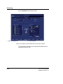
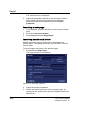
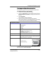
patient.Enter additional patient information if required.
If the unit is configured to display the Patient information
window, follow the steps below:
1. Enter additional patient information if required.
Select between cardiac, obstetric, gynecology... etc. to
enter application specific patient info (Displayed when the
button More is depressed, see Figure 1-15.).
2. Press Begin exam or any active scanning key to start the
examination.
In the scanning screen, the patient information is displayed
on the left side of the Title bar (see Figure 1-16).
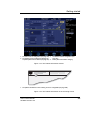
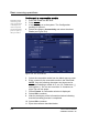
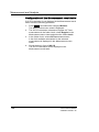
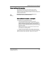
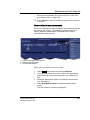
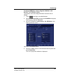
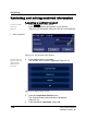
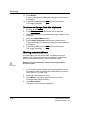
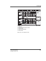
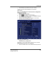
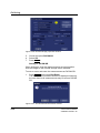
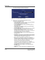
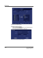
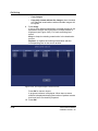
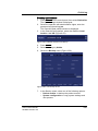
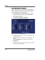
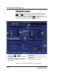
1. Press one of the headings to sort the list
accordingly.
4. Extended menu
2. Select the column heading border and drag to
adjust column width.
5. The system can be configured to display the
Advanced search tool as default (see
page 321).
3. Select new archive and other pre-defined
services.
6. Expended Patient record displaying belonging
examinations
Figure 1-14: The Search/Create Patient window
44
Vivid i User’s Manual
2378958-100 Rev. 02
Getting started
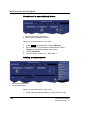
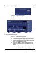
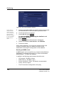
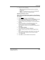
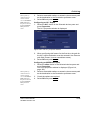
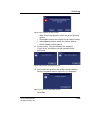
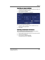
1. The date format is configurable (see page 327). 3. The Address field is configurable (see
page 321).
2. The window can be configured to display the
expanded patient info as default (see page 321). 4. Select patient information category.
Figure 1-15: The Patient Information window
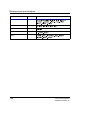
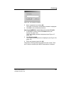
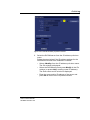
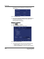
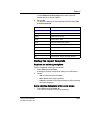
1. The patient information on the scanning screen is configurable (see page 289).
Figure 1-16: The Patient information on the scanning screen
Vivid i User’s Manual
2378958-100 Rev. 02
45
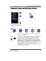
Getting started
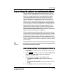
Connectivity on the Vivid i ultrasound unit
Refer to page 186
for further information on connectivity
setup.
The connectivity on the Vivid i Ultrasound unit is based on the
Dataflow concept. A Dataflow is a set of pre-configured
services (e.g. DICOM services like storage, worklist, verify etc.
or other service types like video print, standard print or
messaging). When starting an examination, the user selects a
pre-configured Dataflow that will automatically customize the
ultrasound unit to work according to the services associated to
the Dataflow.
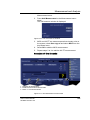
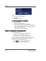
Selecting a Probe and an Application
The combination
Probe-Application
may be user-defined. See page 291
for information on
probe/application
configuration.
Probes and their related applications are selected from the
Probes and applications pop-up menus as described below.
Only probes currently connected are displayed in the pop-up
menu. Only applications appropriate for the type of probe
selected are shown.
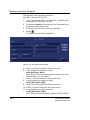
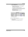
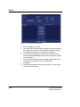
To select a probe and an application
1.
2.
3.
To select a probe
with the default application, press SET
twice on the actual
probe.
4.
5.
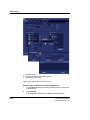
Press APPLICATION on the control panel.
A list of the connected probes is displayed.
Trackball to the desired probe.
Press SET.
An Application menu for the selected probe is displayed.
Trackball to the desired application.
Press SET to launch the application.
Make sure that the probe and application names displayed on the
screen correspond to the actual probe and application selection.
CAUTION
46
Check that the correct TI category is displayed (see Chapter 14,
"Thermal Index" on page 353). TIB must be displayed when a
fetal application is selected.
Vivid i User’s Manual
2378958-100 Rev. 02
Basic scanning operations
Chapter 2
Basic scanning operations
This chapter describes basic operations related to scanning.
Some operations described in this chapter are fully described
in the respective chapters throughout the manual.
This chapter includes the following information:
• Assignable keys and Soft Menu Rocker ..................................... .... 49
• Using the Soft Menu Rocker ...................................................... 53
• Trackball operation ....................................................................... .... 54
• Trackball assignment ................................................................. 54
• The system menu ....................................................................... 55
• Cineloop operation ....................................................................... .... 56
• Cineloop overview ...................................................................... 56
• Cineloop controls ....................................................................... 58
• Using cineloop ............................................................................ 59
• Storing images and cineloops ..................................................... .... 60
• To store a single image .............................................................. 60
• To store a cineloop ..................................................................... 60
• Using removable media ................................................................ .... 61
• Recommendation concerning CD and DVD handling ................ 61
• Writing on CD or DVD media ..................................................... 61
• Formatting removable media ..................................................... 61
• Ejecting removable media .......................................................... 63
• Zoom .............................................................................................. .... 63
• To Magnify an image .................................................................. 63
• Performing measurements .......................................................... .... 63
• Physiological ECG trace .............................................................. .... 64
• Connecting the ECG .................................................................. 64
• Physio controls ........................................................................... 65
• Displaying the ECG trace ........................................................... 66
Vivid i User’s Manual
2378958-100 Rev. 02
47
Basic scanning operations
• Adjusting the display of the ECG trace ....................................... 66
• Annotations ................................................................................... ..... 67
• To insert an annotation ...............................................................67
• To edit annotation ....................................................................... 70
• To erase annotation .................................................................... 70
• Configuration of the pre-defined annotation list .......................... 71
• Bodymarks .................................................................................. 73
48
Vivid i User’s Manual
2378958-100 Rev. 02
Basic scanning operations
Assignable keys and Soft Menu Rocker
1. Active mode & status
2. Filling gauge (progress bar)
3. Selected control shows highlighted
frame
Figure 2-1: A: the 4-Way Rocker; B: Soft Menu; C: the assignable
keys on the control panel.
To toggle between
modes in combined
mode, press ACTIVE
MODE.
The function of the assignable keys and the controls assigned
to the soft menu vary according to the mode in which the
system is running. A detailed description of each function is
provided with each scanning mode in the following imaging
mode sections. In combined modes (i.e. combined Color flow
and PW Doppler), one mode is active (live) while the other is
frozen. In this case, the assignable keys and Gain rotary knob
controls parameters associated with the active mode.
Switching the active mode will change the key and Gain rotary
knob assignments accordingly.
Vivid i User’s Manual
2378958-100 Rev. 02
49
Basic scanning operations
Using the Assignable Keys Soft Menu
The bottom of the display screen contains a graphics area of
soft-menu and assignable keys. This area of the screen is
designed to match a parallel set of physical buttons (the
assignable keys [refer to Figure 2-1]), located on the upper
portion of the control panel. An example of a soft-menu is
shown in below.
Figure 2-2: The Assignable Keys and Soft Menu
The soft-menu provides access and user control of different
system parameters.
The contents of the soft-menu is different for every system
mode. This provides access to the relevant settings in each of
the different modes.
There are several different control key elements in the
soft-menu area, as follows:
Variable Single parameter button
In this example, the “Baseline” parameter can be increased by
pressing the upper or right-hand area of the corresponding
assignable circular button on the keyboard. The same
parameter can be decreased by pressing on the lower or
left-hand area of the same button.
50
Vivid i User’s Manual
2378958-100 Rev. 02
Basic scanning operations
The bar in the center of the button graphic changes its length to
reflect the change in the value of the controlled parameter.
An alternative method for modifying the parameter associated
with this button is to click with the mouse pointer on the
relevant area of the button graphic.
Variable Dual parameter button
In this example the button has access to either “Frame Rate”
or “Low Vel. Reject” parameters.
When the “Frame Rate” upper label is highlighted, the
parameter “Frame Rate” can be increased by pressing on the
right-hand area of the circular assignable button and
decreased by pressing on the left-hand area of the button.
When pressing on the bottom area of the button, the bottom
label (“Low vel. Reject” in this example) will be highlighted. In
this case, from now on, pressing the right or left area of the
circular assignable button will either increase or decrease
respectively the value of the lower (highlighted) parameter.
Pressing, at this pont, on the upper part of the circular button
will, again, associate the button with the upper labeled
parameter.
An alternative method for modifying one of the parameters
associated with this button is to click with the mouse pointer on
the relevant area of the assignable button graphic.
Vivid i User’s Manual
2378958-100 Rev. 02
51
Basic scanning operations
On/Off Toggle button
In this example the active green indicator indicates that the
Variance setting is set ON. The “Simultaneous” function is
toggled OFF (there is no green indicator).
The user can press the matching upper button to toggle the
“Variance” function ON or OFF.
User can press the matching lower button to toggle the
“Simultan.” function ON or OFF.
Alternatively, the user can click with the mouse pointer on the
relevant button graphic to set the function ON or OFF
Soft Menu rocker button
The circular button on the bottom-right area of the screen acts
as a soft-menu rocker button. It has access to a different type
of soft-menu which pops up on the right portion of the screen.
52
Vivid i User’s Manual
2378958-100 Rev. 02
Basic scanning operations
Using the Soft Menu Rocker
The Soft menu Rocker on the control panel enables the
adjustment of controls mapped in the Soft menu Window (see
Figure 2-1).
The first row of the soft menu indicates the name of the active
mode and its status (freeze/live). The following rows list the
mode-specific controls.
The relative setting of each control is indicated by a gauge bar
filling the cell as the control value increases.
To select a control from the menu
1.
2.
Vivid i User’s Manual
2378958-100 Rev. 02
Press any part of the 4-way rocker to display the soft menu.
Press the vertical arrows on the 4-way Rocker to navigate
up or down through the menu.
The frame of the selected row is highlighted.
53
Basic scanning operations
To adjust values
Note: when softmenu is not accessed for a defined
period of time it will
time-out and disappear from the display.
1.
Press one of the horizontal arrows on the 4-way Rocker to
adjust the setting of the selected control.
- Right arrow increases control setting.
- Left arrow decreases control setting.
Trackball operation
Different functions can be assigned to the trackball depending
on the current active mode. The trackball functions are
organized in functional groups. The trackball functional groups
are displayed in the lower right corner of the screen. Each
group can have one or more controls that can be selected
using the keys on the trackball area as described below.
The trackball area consists of:
•
The trackball: used as a cursor control in acquisition mode,
scrolling control in freeze mode and as a selecting tool (like
a mouse cursor) in post-processing mode.
•
The ZOOM key: enables quick access to control zoom
position and/or size (see Figure 2-3).
•
The TRACKBALL key: Toggles between the available
trackball function assignments displayed in the Status bar.
•
The SET key: Performs the selected control or highlighted
menu item.
•
The UPDATE MENU key: enables quick access to various
functions form a pop-up menu (see Figure 2-3).
•
The STORE key: enables digital storage of information
displayed in the currently-active image window (see
Figure 2-3).
Trackball assignment
The trackball has a multi-mode function. The functions
available from the trackball are mode dependent. The available
trackball functions for the active mode are displayed on the
right side of the Status line (Figure 2-3).
54
Vivid i User’s Manual
2378958-100 Rev. 02
Basic scanning operations
To change trackball assignment
1.
Press TRACKBALL in the Trackball area until the desired
function is selected highlighted.
The system menu
The system menu enables a quick access to image related
functions (see Figure 2-3).
1. Zoom key: select to enlarge or reduce the image size on the screen.
2. Trackball key: select trackball assignment from the functions available in the Status line.
3. Set key: perform the selected control or highlighted menu item
4. Update Menu key: select the operation to perform from the pop-up System menu.
5. Store key: store information displayed in the currently-active image window
Figure 2-3: The Trackball area
Vivid i User’s Manual
2378958-100 Rev. 02
55
Basic scanning operations
Cineloop operation
When no ECG is
connected, a cine
gauge is displayed
indicating the current frame. in the
cineloop.
When the scan mode is frozen, the unit automatically displays
cineloop boundary markers on either side of the last detected
heart cycles. The cineloop boundaries can be adjusted using
the cineloop assignable controls to cover one or more heart
cycles.
Cineloop overview
1. ECG
4. Right marker
2. Left marker
5. Heart rate or Cine speed (in replay)
3. Current frame
6. Cine frame number values
Figure 2-4: The cineloop controls display
56
Vivid i User’s Manual
2378958-100 Rev. 02
Basic scanning operations
2. Image Store
1. Assignable keys:
• Left marker
• Right marker
• Cycle select
• Number of cycles
• First Cycle
• Last Cycle
• Sync
• Cineloop
• Select all
3. Freeze: Start/stop cineloop
4. Trackball:
• Scroll (in freeze)
• Cine speed (in replay)
Figure 2-5: The cineloop controls on the front panel
Vivid i User’s Manual
2378958-100 Rev. 02
57
Basic scanning operations
Cineloop controls
Cineloop assignable controls
Left / Right Marker
Move the left and right markers to expand or trim the cineloop
boundaries.
Cycle select
Selects the heart cycle to be played back.
Number of cycle
Controls the number of heart cycles to be included in the loop.
Select All
Select all heart cycles.
First cycle / Last cycle
Selects the first or last heart cycle to be played back.
Cineloop
Starts cineloop acquisition.
Cineloop Freeze Control
2D Freeze
Toggles between replay and freeze modes.
Cineloop trackball controls
Scroll
When the scan mode is frozen, trackball to move the current
marker and review the images
Cine speed
In cine replay mode, move the trackball left or right to adjust the
speed of the cineloop playback.
58
Vivid i User’s Manual
2378958-100 Rev. 02
Basic scanning operations
Using cineloop
Selection of a cineloop
1.
2.
3.
4.
To jump directly to
the first or to the
last heart beat press
the assignables
FIRST CYCLE or
LAST CYCLE.
5.
6.
Press FREEZE.
The left and right markers on the ECG trace are displayed
on either side of the last detected heart cycle.
Press the 2D FREEZE button to un-freeze the cineloop and
let it run between the default setting of left and right borders.
To modify setting of the left or right borders, press the
CINELOOP assignable.
The selected heart beat is played back.
Press on the assignable CYCLE SELECT to move from heart
beat to heart beat to select the heart cycle of interest.
Press on the assignable NUM CYCLES to increase or
decrease the number of heart beats to be played back.
Adjust LEFT MARKER and RIGHT MARKER assignables to trim
or expand the cineloop boundaries.
Adjustment of cineloop playback
1.
2.
If in freeze mode, press the assignable 2D FREEZE to start
cineloop replay.
Use the Trackball to increase or decrease the speed of the
cineloop playback.
The speed factor is displayed on the right side of the ECG
(see Figure 2-4).
To view a cineloop frame by frame
1.
2.
Vivid i User’s Manual
2378958-100 Rev. 02
If not in freeze mode, press the 2D FREEZE button to freeze
the cineloop.
Use the Trackball to scroll through the cineloop frame by
frame.
Or
Use the Speed/Frame softkey button.
59
Basic scanning operations
Storing images and cineloops
Images stored on
the clipboard during the scanning
session are for immediate purposes.
At the end of the examination, the data
should be archived
in the patient archiving system (refer to page 153).
Images and cine-loops can be stored at any time during the
scanning session. A thumbnail of the stored image is displayed
on the clipboard on the scanning screen. An icon will also be
displayed in the Image Browser and Image Selection screens.
The amount of data stored from 2D live is defined by the
settings of the current application. The application setting
controls the number of cycles included (or time span if ECG is
not active), time span before R-wave...etc (refer to page 289
and page 291 for further information).
The amount of data stored in images from 2D replay is
determined by the defined cineloop.
Images can be stored in either DICOM and GE Raw Data
formats or DICOM format only, depending in the dataflow
configuration (refer to page 310 for further information).
To store a single image
1.
2.
Press FREEZE.
Press STORE to store the image digitally.
The thumbnail of the image is displayed on the clipboard.
See also page 156 for further information.
To store a cineloop
While in scanning mode, press the STORE button to store the
last heart-cycle loop. It is possible to configure this function in
several ways. Cineloops may be stored directly or after
preview, depending on how the system is configured.
While in cine-loop preview mode press STORE to store the
selected loop.
Cineloop length and loop selection is adjustable in several
ways. The procedure for cineloop storage is described on
page 156.
60
Vivid i User’s Manual
2378958-100 Rev. 02
Basic scanning operations
Using removable media
The following removable media can be used for data storage:
•
5 1/4” Magneto Optical disk (from Sony only, 1.3, 2.3, 2.6,
5.4, 8.6 and 9.1 Gb)
•
USB Flash Card
•
CD-R (CD-RW is not supported.)
•
DVD-R
Use only 24x or higher CD-R.
CAUTION
Recommendation concerning CD and
DVD handling
To avoid data loss, never touch the recordable surface of a
disk. Handle the disk only by the outer edge. Do not place it
face down on a hard surface. Fingerprints or scratches will
make the disk unusable. Before usage, verify that disk surface
has no visible scratches. If there are any scratches, do NOT
use the disk.
Writing on CD or DVD media
Use specifically recommended for writing on CD or DVD
media. Never use a solvent-based permanent marker on such
media. The following pens are recommended:
•
Dixon Ticonderoga "Redi Sharp Plus"
•
Sanford "Powermark"
•
TDK "CD Writer"
•
Smart and Friendly "CD Speed Marker"
Formatting removable media
MOD, CD-R and DVD-R media must be formatted before use,
as described in below.
The formatting process will erase any data present on the disk.
CAUTION
Vivid i User’s Manual
2378958-100 Rev. 02
61
Basic scanning operations
To Format a removable media
Removable media
used during Disk
space management
or Backup do not
need to be formatted; the formatting
process is part of
these procedures.
1.
2.
3.
4.
Insert the media into the drive.
Press CONFIG.
If required, log on to the system. The Configuration
package is opened.
Select the category Connectivity and select the sheet
Tools (see Figure 2-6).
Figure 2-6: The Tools Sheet
5.
6.
Select the removable media from the Media pop-up menu.
Enter a name for the removable media in the Label field.
NOTE: Only the following characters and signs can be
used when labelling a media: A-Z, a-z, 0-9, underscore (_)
and hyphen (-). Do not use more than 11 characters or
signs. Do not use space.
7. Select Format. A confirmation window is displayed.
8. Select OK to continue.
9. Wait for the display of the Information window indicating
that the formatting process is completed.
10. Select OK to continue.
11. Eject the media as described below.
62
Vivid i User’s Manual
2378958-100 Rev. 02
Basic scanning operations
Ejecting removable media
Do not eject the CD
using the button on
the CD drive.
1.
Press ALT+E to eject the disk.
The Eject device menu is displayed (Figure 2-7).
Figure 2-7: The Eject device menu
2.
Select the relevant media.
The selected media is ejected.
Zoom
The Vivid i supports Variable display zoom. The Display zoom
magnifies the image display in both frozen and live 2D,
M-Mode and combined modes with Doppler.
To Magnify an image
Zoom is available in
live and replay.
1.
2.
3.
4.
Press the ZOOM button. The resulting magnified image
appears in the acquisition window while the un-magnified
image is displayed in the control window showing the
outlined zoom region.
Use the Trackball to position the zoom area over the
desired portion of the image.
Use the SET button to toggle between Zoom-Scale and
Zoom-location (panning). Both Scale and Pan are
controlled by trackball.
To turn off the Display zoom, press the ZOOM button again.
Performing measurements
To perform measurements:
1.
Vivid i User’s Manual
2378958-100 Rev. 02
Press MEASURE to enter the Measurement mode.
Refer to page 109 for further information.
63
Basic scanning operations
Physiological ECG trace
The physiological module consists of a single connector, which
can accept either a set of electrodes cable or an External-ECG
cable, capable of handling external ECG signals from other
diagnostic ECG devices.
The scanned image that is displayed is synchronized with the
ECG trace. In M-Mode or Doppler, the traces are synchronized
to that particular mode's sweep.
The operator can control the gain, the position and the sweep
rate of the traces using the assignables on the control panel.
Connecting the ECG
The ECG cable consists of a circular connector on one end of
the cable and a triple color-coded electrode connectors on the
other end. Each electrode cable hooks up to the appropriate
stick-on electrode by a color-coded clip type connector.
The color-coding of the electrodes follows one of two standards
that are common in different parts of the world. Refer to the
following table:
AHA (USA)
64
IEC (Europe, Asia)
RA: White
L: Yellow
LA: Black
R: Red
RL: Green
N: Black
Vivid i User’s Manual
2378958-100 Rev. 02
Basic scanning operations
Figure 2-8: The Patient ECG Connector Port
Physio controls
Physio assignable controls
Common controls
Horizontal sweep
Adjust the refresh rate of the physiological trace. This control is
active only in 2D and color modes. The sweep speed of the
physio traces in M-Mode and Doppler is identical to the
M-Mode or Doppler horizontal sweep adjusted by the user.
Gain
Enables the user to change the amplitude of the physiological
trace displayed on the screen.
Position
Enables the user to move the physiological trace on the screen.
ECG
Turns the ECG trace on and off.
Vivid i User’s Manual
2378958-100 Rev. 02
65
Basic scanning operations
Displaying the ECG trace
To turn the ECG
display off, press
PHYSIO and press
the assignable ECG
Cardiac applications
The ECG is turned on by default in all cardiac applications.
Other applications
1.
2.
Press PHYSIO on the control panel to get access to the ECG
controls.
Press the assignable ECG to display the trace.
Adjusting the display of the ECG trace
Adjusting the ECG trace sweep speed
1.
2.
Press PHYSIO on the control panel.
Adjust the assignable button HORIZONTAL SWEEP to change
the sweep speed.
Adjusting the ECG trace amplitude
The ECG signal's
amplitude may vary
between patients
due to different skin
moisture and other
physiological parameters.
66
1.
2.
Press PHYSIO on the control panel.
Adjust the assignable button GAIN to adjust the amplitude of
the trace.
Adjusting the ECG trace position
1.
2.
Press PHYSIO on the control panel.
Adjust the assignable button POSITION to move the trace
vertically.
Vivid i User’s Manual
2378958-100 Rev. 02
Basic scanning operations
Annotations
Text annotations may be inserted anywhere on the screen. The
annotation can be free text or a pre-selected text from a
mode-specific annotation menu or a user-defined library.
1. Select to display annotation for other
applications
2. Free text
3. Draw an arrow
4. Edit previous annotation
5. Pre-defined application-specific
annotations
6. Exit annotation mode
Figure 2-9: The mode-specific annotation menu
To insert an annotation
Free text
While typing, use
BACKSPACE to delete backward.
1.
2.
3.
Type the required text.
A suggested word corresponding to the entered characters
is displayed while typing. Press TAB to enter the suggested
word.
Trackball the text entered to the insertion position.
Press SET to add the annotation.
Pre-defined annotation
Word selection from the Annotation menu
1. Press the alphanumeric key TEXT.
A list of application specific pre-defined texts is displayed
(see Figure 2-10).
To display a list from another application, select the
heading and choose another application.
2. Trackball to the required abbreviation.
Vivid i User’s Manual
2378958-100 Rev. 02
67
Basic scanning operations
3.
4.
5.
Press SET.
Trackball to the position at which the annotation is to be
inserted.
Press SET to add the annotation.
1.
2.
3.
4.
5.
To draw an arrow
Press Arrow in the Annotation menu.
Trackball to the start position of the arrow to draw.
Press SET to anchor the arrow.
Trackball to the end position of the arrow to draw.
Press SET to fix the arrow.
Word selection from the Library
Pre-defined text can be organized in a user configurable,
application dependent library with three different sections.The
user can easily select a pre-defined text from the Library using
the ARROW keys.
Creating a Library
1. Press CONFIG.
2. In the Configuration package, select Measure.
3. In the Measure Category select Customize.
The Customize sheet is displayed (see Figure 2-10).
4. Select a pre-defined text in the Application pane.
5. Select Add in the desired section.
6. Repeat step 4 and 5 to populate the library.
7. To remove a pre-defined text from the library, select the
pre-defined text to remove and press Del.
8. To order the pre-defined text in a section, select the
pre-defined text to move and select Up or Down buttons to
move the word accordingly.
9. To exchange sections order, enter the sections to swap
next to Swap columns button and press Swap columns.
10. Press Save to store the library.
68
Vivid i User’s Manual
2378958-100 Rev. 02
Basic scanning operations
1. The Application pane
2. Library section
3. Insert selected pre-defined text in the section.
4. Remove selected pre-defined text from the section.
5. Move pre-defined text within the section.
6. Re-order sections.
7. Save Library
Figure 2-10: The Arrow menu sheet
1.
2.
3.
4.
Vivid i User’s Manual
2378958-100 Rev. 02
Using the Library
Press any ARROW key.
The pre-defined texts from the last used group are
displayed in the Status bar at the bottom of the screen,
with the active word within square brackets.
To select a pre-defined text within a section, press ARROW
UP or ARROW DOWN until the desired word is selected.
To change section, Press LEFT ARROW until the desired
section is displayed in the Status bar.
To insert the selected pre-defined text, press RIGHT ARROW.
69
Basic scanning operations
Text overlays
There are 2 layers of the text in annotations, which can be
selected by toggling the TEXT key. Text1 is the default choice.
This function enable the user to show/hide different (or all)
annotations.
To edit annotation
1.
2.
3.
4.
5.
6.
Press the alphanumeric key TEXT.
Press Edit in the Annotation menu.
The pointer is changed to a cross marker.
Trackball to the annotation to edit.
Press SET.
Once selected, the annotation can be moved freely.
The text can be edited using the following alphanumeric
keys:
• RIGHT ARROW: moves the text cursor forward.
• LEFT ARROW: moves the text cursor backward.
• TAB: moves the text cursor by word forward.
• SHIFT + TAB: moves the text cursor by word backward.
• BACKSPACE: deletes backward.
• DELETE: deletes the selected word.
• INSERT: toggles the text entry state from overwrite to
insert mode.
Do the appropriate changes to the annotation.
Press SET to anchor the edited annotation.
To erase annotation
The user can erase all annotations on the screen in one
operation or erase annotations one by one.
To erase all annotations
1.
70
Press the alphanumeric key PAGE ERASE.
If using text overlays, page erase applies only to the
displayed layer(s).
Vivid i User’s Manual
2378958-100 Rev. 02
Basic scanning operations
Configuration of the pre-defined
annotation list
1.
2.
3.
Press CONFIG.
In the Configuration package, select Measure.
In the Measure category select Annotation.
The Annotation sheet is displayed where the user can add,
delete or re-arrange the annotation text (see Figure 2-11).
To re-arrange the annotation list
1.
2.
3.
4.
Trackball to the actual annotation text.
Press SET.
Press the relevant button (i.e Delete, Move up or Move
down) to apply change.
Press save to store the new annotation list.
To add an annotation text
1.
2.
3.
4.
5.
Vivid i User’s Manual
2378958-100 Rev. 02
Trackball to the text entry field (see Figure 2-11).
Press SET to activate the text cursor.
Type the new annotation text.
Press add.
The new annotation text is added at the end of the list.
Press save to store the new annotation list.
71
Basic scanning operations
1. Rearrange list
2. Delete selected text
3. Reset to factory default
4. Add new text to the list
5. Enter new text
Figure 2-11: The Annotation Menu Configuration Dialog Box
72
Vivid i User’s Manual
2378958-100 Rev. 02
Basic scanning operations
Bodymarks
Bodymarks are small graphic images that represent the
anatomy being examined. Using bodymarks, the user can
indicate the position that the probe was in during the
examination.
Inserting a bodymark
1.
Press the alphanumeric key BODYMARK.
The Bodymark menu is displayed showing a selection of
bodymarks relative to the selected exam category.
1. Select and display bodymark list for
other applications
2. Edit probe marker position and
orientation
3. Erase bodymark
4. Bodymark list for the current
application
5. Insert an arrow
6. Insert user-defined text
Figure 2-12: The Bodymark menu
2.
Trackball to the desired bodymark and press SET.
The bodymark with a probe marker is displayed on the
scanning screen.
1. Probe marker
Figure 2-13: The bodymark with probe marker
3.
Vivid i User’s Manual
2378958-100 Rev. 02
Using the trackball, adjust the position of the probe marker
and press SET.
73
Basic scanning operations
4.
Using the trackball, adjust the probe marker orientation and
press SET.
Editing a bodymark
1.
2.
3.
4.
Press the alphanumeric key BODYMARK.
The Bodymark menu is displayed
Press Edit.
Using the trackball, adjust the position of the probe marker
and press SET.
Using the trackball, adjust the probe marker orientation and
press SET.
Deleting a bodymark
1.
2.
74
Press the alphanumeric key BODYMARK.
The Bodymark menu is displayed
Press Delete.
Vivid i User’s Manual
2378958-100 Rev. 02
Scanning Modes
Chapter 3
Scanning Modes
• 2D-Mode ......................................................................................... .... 77
• 2D-Mode overview ..................................................................... 77
• 2D-Mode controls ....................................................................... 79
• Using 2D .................................................................................... 82
• Optimizing 2D ............................................................................. 82
• M-Mode .......................................................................................... .... 83
• M-Mode overview ....................................................................... 83
• M-Mode controls ........................................................................ 84
• Using M-Mode ............................................................................ 85
• Optimizing M-Mode .................................................................... 87
• Color Mode .................................................................................... .... 88
• Color Mode overview ................................................................. 88
• Color Mode controls ................................................................... 90
• Using Color Mode ...................................................................... 92
• Optimizing Color Mode ............................................................... 93
• PW and CW Doppler ..................................................................... .... 94
• PW and CW Doppler overview ................................................... 94
• PW and CW Doppler controls .................................................... 95
• Using PW/CW Doppler modes ................................................... 98
• Optimizing PW/CW Doppler modes ........................................... 98
Vivid i User’s Manual
2378958-100 Rev. 02
75
Scanning Modes
Introduction
The Vivid i ultrasound scanner provides several basic scanning
modes and several options for combining the use of these
modes.
The following scanning modes are described in this chapter:
•
2D Mode Imaging
•
M-Mode Imaging
•
Anatomical M-Mode
•
Color Mode Imaging
•
Doppler Mode Imaging
•
Angio
See page 156 for
further information
on image and
cineloop storage.
76
When performing an examination using any of these modes,
images and image sequences (cineloops) can be stored. The
examination or part of it can also be stored on video tape,
CD-R, DVD-R and other various media, depending on available
options.
Vivid i User’s Manual
2378958-100 Rev. 02
Scanning Modes
2D-Mode
2D-Mode overview
1. Focus marker
2. Probe orientation marker
3. Status window
4. Soft menu
Controls marked with R are also available in freeze and cine replay
Figure 3-1: The 2D screen (cardiac)
Vivid i User’s Manual
2378958-100 Rev. 02
77
Scanning Modes
1. Assignable keys:
• Width
• Frequency
• Focus
• Frame rate
• Up/Down R
• Left/Right R
• Cineloop (in Freeze, only)
• Dual focus
• B color maps
• Select all
4. Soft menu
• Compress R
• Reject R
• Dynamic Range
• DDP R
• Tilt
• Speckle reduce
• Contour
• Diff On/Off
• Power
2. Zoom
6. 2D
3. Depth
7. Gain
5. Freeze
Figure 3-2: The 2D controls on the front panel
78
Vivid i User’s Manual
2378958-100 Rev. 02
Scanning Modes
In combined mode,
press ACT. MODE to
toggle between
modes and access to
the mode specific
controls.
The 2D mode displays a two-dimensional gray scale image of
the tissue within the probe's field of view. 2D mode can be
combined with:
•
M-Mode, see "M-Mode" on page 83
•
Color Mode, see "Color Mode" on page 88
•
CW or PW Doppler Mode, see "PW and CW Doppler" on
page 94
•
Color and Doppler Modes (triplex)
2D-Mode controls
2D assignable controls
Width
Controls the size or angular width of the 2D image sector. A
smaller angle generally produces an image with a higher frame
rate.
Focus
Changes the location of the focal point(s). A triangular focus
marker indicates the depth of the focal point.
Frame rate
Adjusts frame rate (FPS). The relative setting of the frame rate
is displayed in the status window. When adjusting frame rate,
there is a trade off between spatial and temporal resolution.
Frequency
On some low frequencies, the system switches
automatically to
second-harmonic
mode. The word
“Octave” appears
in the status window.
Enables the adjustment of the probe's operating frequency.
The selected frequency is displayed in the status window. For
some probes/applications the lowest frequency settings will be
Octave imaging settings.
Invert
•
Left/Right Invert: enables a mirror image of the 2D image
to be created. The left/right reference marker V moves to
the other side of the image.
•
Up/Down Invert: enables the 2D image to be flipped
180 degrees.
Dual focus
Activates Dual focus mode. To adjust the location of the Dual
focus, activate the FOCUS assignable.
Vivid i User’s Manual
2378958-100 Rev. 02
79
Scanning Modes
Color maps
Displays a color map menu to optimize the greyscale
presentation. The menu enables an option from a list of
non-linear gray-curves or different 2D-colorized curves to be
selected. Use the trackball to highlight a color map and press
SET to activate the desired map.
Cineloop (in Freeze only)
Allocates different cineloop control functions to the assignable
soft keys.
Gain
When rotated clockwise, increases the overall gain applied to
the received echo signals equally for all depth.
Time Gain Compensation (TGC)
Compensates for depth-related attenuation in an image. The
sliders nearest the operator affect the far field. TGC amplifies
returning signals to correct for the attenuation caused by tissue
at increasing depths.
Depth
Sets the maximum (far field) distance that will be imaged.
Decreasing the depth may allow higher frame rates.
2D Soft menu controls
Compress
Controls the amount of contrast in the 2D image. An index
number is displayed in the status window to indicate the
relative level of compression.
Reject
Adjust reject level. When this control is increased, low-level
echoes are rejected and appear darker in the 2D image. An
index number is displayed in the status window to indicate the
relative level of rejection.
80
Vivid i User’s Manual
2378958-100 Rev. 02
Scanning Modes
Dynamic Range
Enables control of the dynamic range or contrast of the image.
When dynamic range is set high, the image is softer and more
low-level data is visible.
DDP (Data Dependent Processing)
Performs temporal processing which reduces random noise
without affecting the motion of significant tissue structures. An
index number is displayed in the status window (under Proc) to
indicate the relative DDP level.
Tilt
Enables the axis of the 2D image to be tilted to the left or right.
By using this control in combination with angle control the
image can be “aligned” to the direction of interest, and frame
rates be optimized. By default the axis of symmetry of a 2D
image is vertical. (Applicable only for cardiology applications).
Contour
Controls image processing related to the extent of edge
enhancement applied to an image.
Diff On/Off
Affects the level of reverberations in the image. When turned
On, the frame rate (or the number of focal zones) will decrease,
while the reverberations will be attenuated. (Applicable only for
cardiology applications).
Power
When power is reduced, it reduces
the signal-to-noise
ratio, so that the image may become
noisier.
Controls the amount of acoustic power applied in all modes.
When power is set to maximum, it is equal to or less than the
maximum acoustic power permitted by the FDA. The Thermal
Index (TI) and the Mechanical Index (MI) are displayed on the
screen.
Vivid i User’s Manual
2378958-100 Rev. 02
81
Scanning Modes
Using 2D
Refer to page 291
about creating presets.
The 2D-Mode is the system's default mode.
1. Press 2D on the control panel to access 2D mode.
Check the Display's
brightness and contrast setting before
adjusting the unit
imaging controls
(see page 41).
2.
Optimize the image by adjusting the image controls
described in the previous section.
If necessary use preset for optimum performance with
minimum adjustment.
Optimizing 2D
The following controls can be adjusted to optimize the 2D Mode
display:
•
Use the Gain and TGC controls to optimize the overall
image.
•
Use the Depth control to adjust the range to be imaged.
•
Use the Focus control to center the focal point(s) around
the region of interest.
•
Use the Frequency (move to higher frequencies) or the
Frame rate control (move to lower frame rate) to increase
resolution in image
•
Use the Frequency (move to lower frequency) to increase
penetration.
•
Use the Reject control to reduce noise in the image.
•
Use the DDP control to optimize imaging in the blood flow
regions and make a cleaner, less noisy image.
Always use the minimum power required to obtain acceptable
images in accordance with applicable guidelines and policies.
WARNING
82
Vivid i User’s Manual
2378958-100 Rev. 02
Scanning Modes
M-Mode
M-Mode overview
1. Time motion cursor conventional M-Mode
2. Depth Scale
3. Focus Marker
4. Time Scale
Figure 3-3: The cardiac M-Mode screen (top/bottom)
This unit has two types of M-Mode:
•
Conventional M-Mode (MM): displays a distance/time plot
of a cursor line in the axial plane of the 2D-image.
•
Anatomical M-Mode (AMM): displays a distance/time plot
from a cursor line, which is independent from the axial
plane. AMM is available in greyscale or in color modes.
M-Mode and 2D Mode display areas can be side by side or
top/bottom. Conventional M-Mode can be combined with Color
(see "Color M-Mode overview" on page 89).
Vivid i User’s Manual
2378958-100 Rev. 02
83
Scanning Modes
M-Mode controls
M-Mode assignable controls
Horizontal sweep
Adjusts the horizontal refresh rate of the M-Mode area of the
display. Horizontal sweep does not change the acquisition
resolution, so that user can change the horizontal sweep in
replay (with no loss of quality).
On some low frequencies, the system switches
automatically to
second-harmonic
mode. The word
“Octave” appears
in the status window.
Frequency/Resolution
Enables the adjustment of the probe's operating frequency.
Rotate the knob clockwise to increase the frequency. The
selected frequency is displayed in the status window. For some
probes/applications the lowest frequency settings will be
Octave imaging settings.
Focus
Changes the location of the focal point(s). A triangular focus
marker indicates the depth of the focal point.
Contour
Controls image processing related to the extent of edge
enhancement applied to an image.
Up/Down
Flips the M-Mode display 180 degrees.
Layout
Toggles the display arrangement to define relative dimensions
of the 2D area, M-mode area, and their position which is either
top/bottom or side-by-side.
Color maps
Displays a color map menu to optimize the greyscale
presentation. The menu enables an option from a list of
non-linear gray-curves or different colorized curves to be
selected. Use the trackball to point to a color map and press
SET to activate the desired map.
84
Vivid i User’s Manual
2378958-100 Rev. 02
Scanning Modes
M-Mode Soft menu controls
Compress
Controls the amount of contrast in the image. An index number
is displayed in the status window to indicate the relative level of
compression.
Reject
Adjust reject level. When this control is increased, low-level
echoes are rejected and appear darker in the image. An index
number is displayed in the status window to indicate the
relative level of rejection.
Power
When power is reduced, it reduces
the signal-to-noise
ratio, so that the image, spectrum or
color scan may become noisier.
Controls the amount of acoustic power applied in all modes.
When power is set to maximum, it is equal to or less than the
maximum acoustic power permitted by the FDA. The Thermal
Index (TI) and the Mechanical Index (MI) are displayed on the
screen.
Dynamic Range
Enables control of the dynamic range or contrast of the image.
When dynamic range is set to High, the image is softer and
more low-level data is visible.
Using M-Mode
Conventional M-Mode (greyscale)
1.
2.
Gain, Frequency,
Focus, Dynamic
Range and Compression affect also
the 2D image.
Gain, Frequency,
Focus, Dynamic
Range and Compression affect also
the 2D image.
3.
4.
While in 2D-Mode press cursor on the control panel.
Use the trackball to position the cursor over the required
area of the image.
Press MM - the M-mode sweep will start to sweep.
Press FREEZE to stop imaging.
OR
1.
2.
Vivid i User’s Manual
2378958-100 Rev. 02
While in 2D-Mode press MM on the control panel. The
M-mode sweep will start to sweep.
Use the trackball to position the cursor over the required
area of the image.
85
Scanning Modes
Gain, Frequency,
Focus, Dynamic
Range and Compression affect also
the 2D image.
3.
4.
Adjust horizontal sweep, Gain, Frequency, Focus, Dynamic
Range, Compression and Contour to optimize the display if
necessary.
Press FREEZE to stop imaging.
Conventional Color M-Mode
1.
2.
3.
4.
While in Color Mode press cursor on the control panel.
Use the trackball to position the cursor over the required
area of the image.
Press MM - the Color M-mode sweep will start to sweep.
Press FREEZE to stop imaging.
OR
1. While in Color Mode press M on the control panel. The
Color M-mode sweep will start to sweep.
2. Use the trackball to position the cursor over the required
area of the image.
3. Adjust horizontal sweep, Gain, Frequency, Focus, Dynamic
Range, Compression and Contour to optimize the display if
necessary.
4. Press FREEZE to stop imaging.
Anatomical M-Mode
Anatomical
M-Mode can also
be used with previously acquired digitally stored 2D
images.
The Trackball assignable Pos (Position) is activated.
The Trackball assignable Angle is
activated.
The Trackball assignable Pos is activated.
86
Anatomical M-Mode is only available for cardiac applications.
1. Enter live M-mode.
2. Press the assignable AMM soft key to enter Live
Anatomical M-mode. Continue to step 4 below.
OR
1. From the 2D Live, press FREEZE.
2. Press MM to access the Freeze Anatomical M-Mode.
3. Use the trackball to position the cursor over the required
area of the image.
4.
5.
6.
Press TRACKBALL to allow free rotation of the solid
full-length cursor line throughout the 2D image.
Rotate the solid cursor line to the desired direction.
Press TRACKBALL twice and reposition the intersection
point to the desired position along the cursor line.
Vivid i User’s Manual
2378958-100 Rev. 02
Scanning Modes
7.
The M-Mode area
of the display updates as the
M-Mode signal is
constructed.
8.
9.
Repeat steps 4. and 5. to change the angle of the solid
cursor line if necessary.
Press TRACKBALL to activate scrolling control on the
trackball.
Use the trackball to scroll through the data acquired at that
location. The M-Mode display will vary accordingly.
Optimizing M-Mode
Refer to page 291
about creating presets.
Except for Contour,
all the controls listed in the optimizing
M-Mode section
will also affect the
2D image.
The use of preset gives optimum performance with minimum
adjustment. If necessary, the following controls can be adjusted
to further optimize the M-Mode display:
•
Adjust Horizontal sweep to optimize the display resolution.
•
Adjust Gain and TGC controls to adjust the range to be
imaged.
•
Use the Frequency (move to higher frequencies) or the
Frame rate control (move to lower frame rate) to increase
resolution in image.
•
Use the Frequency (move to lower frequency) to
increase penetration.
•
Adjust Focus to move the focal point(s) around the region
of interest in the M-Mode display.
•
Adjust Dynamic range to optimize the useful range of
incoming echoes to the available greyscale.
•
Adjust Compress and Contour to further optimize the
display.
•
Adjust Reject to reduce noise while taking care not to
eliminate significant low-level diagnostic information.
Vivid i User’s Manual
2378958-100 Rev. 02
87
Scanning Modes
Color Mode
Color Mode overview
1. Probe orientation marker
2. Color bar
3. Color sector marker
4. Status window
5. Soft menu
Figure 3-4: The Color Mode screen
88
Vivid i User’s Manual
2378958-100 Rev. 02
Scanning Modes
Color M-Mode overview
1. Time motion cursors
2. Color bar
3. Focus marker
4. Flow sector marker
5. Time scale
6. Status window
7. Soft menu
Figure 3-5: The Color M-Mode screen (top/bottom display)
Vivid i User’s Manual
2378958-100 Rev. 02
89
Scanning Modes
Color Mode controls
Color Mode assignable controls
Horizontal sweep (Color M-Mode only)
Adjusts the horizontal refresh rate of the M-Mode area of the
display.
Scale
Adjusts the repetition rate of the Doppler pulses transmitted to
acquire the data for color flow mapping. The Scale (Nyquist
limit) should be adjusted so that no aliasing occurs, while still
having good resolution of velocities. The Nyquist limit should
be somewhat above the maximum velocity found in the data.
Baseline
Adjusts the color map to emphasize flow either toward or away
from the probe. Baseline is available in both Live and Freeze.
LVR (Low Velocity Rejection)
Color data produced by very low
flow may cause interference.
LVR, also called Wall motion filter, enables the extent of low
velocity removal to be adjusted.
Invert
Enables the color scheme assigned to positive and negative
velocities to be inverted. Invert is available in live and cine
replay.
Variance
Controls the amount of variance data added to a color display.
Variance enables computer-aided detection of turbulent flow
(e.g. jets or regurgitation). Variance is available in live and cine
replay.
Color maps
Displays a menu of color map options. Use the trackball to
point to a color map and press SET to activate the desired color
map. Each color map is assigning different color hues to
different velocities.
Cineloop (in Freeze, Color 2D mode only)
Allocates different cineloop control functions to the assignable
soft keys.
90
Vivid i User’s Manual
2378958-100 Rev. 02
Scanning Modes
Color-Mode Soft menu controls
Tissue priority
Emphasize either the color of the color mode or the greyscale
tissue detail of the 2D image. Tissue priority is available in both
Live and Freeze.
Sample volume
Adjusts the size of the color flow Doppler sampling area. Lower
setting gives better flow resolution while a higher setting
increases sensitivity and helps to locate turbulent flows.
Frequency
Enables the adjustment of the transmission frequency to
control the sensitivity or the level of penetration. The selected
frequency is displayed in the status window. Adjusting
Frequency may affect Sample Volume and LVR settings.
Lateral Averaging (Color 2D only)
Smooths the image by averaging collected data along the
same horizontal line. An increase of the lateral averaging will
reduce noise, but this will also reduce the lateral resolution.
Radial Averaging
Use Averaging controls with caution so
as not to obscure
significant diagnostic information
Smooths the image by averaging collected data along the
same radial line. An increase of the radial averaging will reduce
noise, but this will also reduce the radial resolution.
When power is reduced, it reduces
the signal-to-noise
ratio, so that the image may become
noisier.
Controls the amount of acoustic power applied in all modes.
When power is set to maximum, it is equal to or less than the
maximum acoustic power permitted by the FDA. The Thermal
Index (TI) and the Mechanical Index (MI) are displayed on the
screen.
Power
Trackball controls
ROI (Region Of Interest) size
When the trackball command Size is selected (see also
"Trackball operation" on page 54), the height and width of the
color area (or ROI) is adjusted from the trackball.
Vivid i User’s Manual
2378958-100 Rev. 02
91
Scanning Modes
ROI (Region Of Interest) position
When the trackball command Pos (position) is selected (see
also "Trackball operation" on page 54), the position of the color
area (or ROI) is adjusted with the trackball.
Using Color Mode
Color 2D
The assignable controls of the trackball
are displayed in the
trackball status bar
in the bottom right
corner of the
screen.
1.
2.
3.
4.
5.
6.
From an optimized 2D image press COLOR.
Use the trackball to position the ROI frame over the area
to be examined.
Press SET. The instruction Size should be highlighted in the
trackball status bar. If not, press SET again to select Size.
NOTE: If the trackball control Pointer is selected, press
TRACKBALL to be able to select between Position and Size
controls.
Use the trackball to adjust the dimensions of the ROI.
To enlarge or narrow the ROI, move the trackball to the
left or right.
To lengthen or shorten the ROI, move the trackball up or
down.
Press SET when the desired size is obtained, to allow
repositioning of the ROI if desired.
Press FREEZE to stop imaging.
Color M-Mode
The assignable controls of the trackball
are displayed in the
trackball status bar.
1.
2.
3.
4.
5.
92
From M-Mode press COLOR, or from Color-Mode press MM.
Use the trackball to position the color area in the M-Mode
display.
Press the SET button. The instruction Size should be
highlighted in the trackball status bar. If not, press SET
again to select Size.
NOTE: If the trackball control Pointer is selected, press
TRACKBALL to be able to select between Position and Size
controls.
Use the trackball to adjust the dimension of the color area.
To enlarge the color area, move the trackball up
To narrow the color area, move the trackball down.
Press SET when the desired size is obtained.
Vivid i User’s Manual
2378958-100 Rev. 02
Scanning Modes
Optimizing Color Mode
Refer to page 291
about creating presets.
The scale value may
affect FPS, Low Velocity Reject, and
Sample Volume.
Frequency setting
may affect FPS, SV
and Low Velocity
Reject.
The Power setting
affects all other operating modes.
The use of preset gives optimum performance with minimum
adjustment. If necessary, the following controls can be adjusted
to further optimize the Color Mode display:
•
Adjust the Active mode gain to set the gain in the color
flow area.
•
Adjust Scale to the highest setting that provides adequate
flow detection.
•
Adjust Low Velocity Reject to remove low velocity blood
flow and tissue movement that reduces image quality.
•
Adjust Variance to detect flow disturbances.
•
Adjust Sample volume (SV) to a low setting for better flow
resolution, or a higher setting to more easily locate
disturbed flows
•
Adjust Frequency to optimize the color flow display. Higher
settings improve resolution. Lower settings improve depth
penetration and sensitivity. This does not affect the
frequency used for 2D and M-Mode.
•
Adjust Power to obtain an acceptable image using the
lowest setting possible.
Adjust the following settings to further optimize display of the
image:
•
Use Invert to reverse the color assignments in the color
flow area of the display.
•
Use Tissue priority to emphasize either the color flow
overlay, or the underlying greyscale tissue detail.
•
Use Baseline to emphasize flow either toward or away
from the probe.
•
Use Radial and Lateral Averaging to reduce noise in the
color flow area. Radial and Lateral Averaging smooths the
image by averaging collected data along the same
horizontal line. An increase of the lateral averaging will
reduce noise, but this will also reduce the lateral resolution.
Use all noise reduction controls with care. Excessive
application may obscure low level diagnostic information.
CAUTION
Vivid i User’s Manual
2378958-100 Rev. 02
93
Scanning Modes
PW and CW Doppler
PW and CW Doppler overview
1. Sample volume (PW only)
2. Angle correction marker
3. Velocity scale
4. Low velocity reject
5. Nyquist velocity
6. Doppler baseline
7. Frequency scale (optional, see page 288)
8. Status window
9. Soft menu
Figure 3-6: The PW/CW Doppler Mode screen
94
Vivid i User’s Manual
2378958-100 Rev. 02
Scanning Modes
PW and CW Doppler controls
PW and CW Doppler assignable controls
Horizontal sweep
Adjusts the horizontal refresh rate of the Doppler area of the
display. Horizontal sweep is available in live and cine replay.
Baseline
Enables the Doppler baseline to be shifted up and down. The
default Doppler baseline is set at the center of the vertical
aspect of the Doppler display, dividing evenly the flow toward
and away from the probe. By adjusting the baseline a larger
portion of the analysis is assigned to the flow direction present.
Baseline is available in live and cine replay.
Maximum velocity
depends on sample
volume size, sample
volume position and
frequency settings.
Velocity range
Enables the vertical scale of the Doppler spectrum and the
maximal detectable velocity to be modified. Velocity range
directly controls the pulse repetition frequency, which is
responsible for the setting of the Nyquist limit (the ability to
detect maximum velocity without aliasing).
Scale
Enables the low velocity portions of the spectrum to be filtered,
since the Doppler spectrum and audio may contain strong
wall-motion signals. The amount of Low Velocity Reject. is
indicated by the green vertical bar at the right end of the
baseline.
If the Doppler mode
is combined with
Color mode, the
color map will be
also inverted.
Invert
Enables the Doppler spectrum to be flipped 180 degrees, so
that negative velocities are displayed above the baseline and
positive velocities below the baseline. Invert is available in live
and cine replay.
LPRF (PW mode)
Sets the pulse repetition frequency for the PW Doppler
acquisition of flow data. Enables toggling between high and low
Pulse Repetition Frequency (PRF). When the Doppler PRF is
raised beyond a certain limit, more than one Doppler gate is
displayed on the screen.
Vivid i User’s Manual
2378958-100 Rev. 02
95
Scanning Modes
Layout
Toggles the display arrangement to define relative dimensions
of the 2D area, Doppler-spectrum area, and their position
which is either top/bottom or side-by-side.
Color maps
Displays a drop down menu of different Doppler colorization
maps.Use the trackball to select the desired map and press
SET to activate the map.
Quick angle and Angle correction
In non-cardiac applications, Angle
correction is controlled from the
Trackball.
Enables correction of the Doppler velocity scale by defining the
angle between the Doppler beam and the investigated blood
vessel or blood flow. A thin cross bar on the Doppler cursor will
rotate as the control is adjusted. Angle correction is available in
both Live and Freeze.
Quick angle adjusts the angle by 60 degrees.
Angle correction adjusts the angle between zero and
90 degrees with one degree increment.
PW/CW Doppler Soft menu controls
Sample volume
In PW mode, set the longitudinal size of the region to be
sampled for measurement. Adjusting Sample volume may
affect the PRF (Nyquist limit) settings. SV does not apply to
CW mode, where the volume sampled is the full length of the
area indicated by the cursor line.
Compress
Enables control over the contrast of the Doppler spectrum.
When compression is raised, the spectrum image becomes
softer and some low level background noise may appear.
Compress is available in both Live and Freeze.
Reject
Enables undesirable background noise to be removed from the
Doppler spectrum resulting in a darker background. Reject is
available in both Live and Freeze.
96
Vivid i User’s Manual
2378958-100 Rev. 02
Scanning Modes
Frequency
Adjusts the transmission frequency in Doppler to control
sensitivity or level of penetration. The selected frequency is
displayed in the status window. Adjusting Frequency may affect
Sample Volume (PW) and LVR settings.
Frame rate
Adjusts the frame rate. The relative setting of the frame rate is
displayed in the status window (under 2D).
Power
When power is reduced, it reduces
the signal-to-noise
ratio, so that the image may become
noisier.
Controls the amount of acoustic power applied in all modes.
When power is set to maximum, it is equal to or less than the
maximum acoustic power permitted by the FDA. The Thermal
Index (TI) and the Mechanical Index (MI) are displayed on the
screen.
Vivid i User’s Manual
2378958-100 Rev. 02
97
Scanning Modes
Using PW/CW Doppler modes
Controls and operations for PW and
CW mode are the
same unless otherwise noted.
There are two ways to start PW/CW Doppler:
Alternative 1
1.
2.
Sample Volume adjustment may affect
the Scale, Frame
rate and LV rej. settings.
3.
Press PW or CW. A scanning screen is displayed with a
Doppler cursor on the 2D mode image and a Doppler
spectrum in the lower part of the screen.
Use the trackball to position the Doppler cursor line and in
PW the sample volume location over the area of interest.
In PW, with the Soft menu rocker key, adjust the sample
Volume (SV):
To enlarge the SV, press the Right arrow of the rocker
To narrow the SV, press the Left arrow of the rocker.
Alternative 2
1.
2.
3.
Press CURSOR on the control panel. A cursor line is
displayed on the 2D image.
With the trackball adjust the position of the cursor line.
Press PW or CW.
Optimizing PW/CW Doppler modes
Refer to page 291
about creating presets
Frequency and
Frame rate settings
may affect the Low
Velocity Reject.
98
The use of preset gives optimum performance with minimum
adjustment. If necessary, the following controls can be adjusted
to further optimize the PW/CW modes display:
•
Adjust the Active mode gain to set the gain in the spectral
Doppler area.
•
Adjust Low velocity reject to reduce unwanted low
velocity blood flow and tissue movement.
•
In PW mode, adjust Sample volume to low setting for
better resolution, or higher setting to more easily locate the
disturbed flows.
•
Adjust the Compress setting to balance the effect of
stronger and weaker echoes and obtain the desired
intensity display.
•
Adjust Frequency to optimize flow display. Higher setting
will improve resolution and the lower setting will increase
the depth penetration.
•
Adjust Frame rate to a higher setting to improve motion
detection, or to a lower setting to improve resolution.
Vivid i User’s Manual
2378958-100 Rev. 02
Scanning Modes
The Doppler Power
setting affects only
Doppler operating
modes.
•
Adjust Power to obtain an acceptable image using the
lowest setting possible. This is particularly important in CW
mode, as the energy duty cycle is 100% (constant).
Use all noise reduction controls with care. Excessive
application may obscure low level diagnostic information.
CAUTION
Adjust the following settings to further optimize the display of
the image.
•
Use the Horizontal sweep to optimize the sweep speed.
•
To view signal detail, use the Velocity range to enlarge the
vertical spectral Doppler trace.
•
Use Invert to reverse the vertical component of the spectral
Doppler area of the display.
•
Use Angle correction to steer the ultrasound beam to the
blood flow to be measured (Not typically required during
cardiac studies).
Vivid i User’s Manual
2378958-100 Rev. 02
99
Scanning Modes
100
Vivid i User’s Manual
2378958-100 Rev. 02
Purposely left empty
Chapter 4
Purposely left empty
For Future purposes
Vivid i User’s Manual
2378958-100 Rev. 02
101
Purposely left empty
102
Vivid i User’s Manual
2378958-100 Rev. 02
Contrast Imaging
Chapter 5
Contrast Imaging
• Introduction ................................................................................... .. 104
• Left Ventricular Contrast Imaging ............................................... .. 104
• LV Contrast overview ............................................................... 105
• LV Contrast controls ................................................................. 105
• Running LV Contrast ................................................................ 108
• Optimizing LV Contrast ............................................................ 108
Vivid i User’s Manual
2378958-100 Rev. 02
103
Contrast Imaging
Introduction
Vivid i supports Left Ventricular Contrast imaging: Optimized
for endocardial border detection and assessment of wall motion
and wall thickening.
Left Ventricular Contrast Imaging
The Left Ventricular (LV) Contrast application has an optimized
system preset for optimal resolution of endocardial borders and
for optimal assessment of wall motion and wall thickening.
The LV Contrast application may help to identify LV thrombus
and evaluate wall motion.
Misdiagnosis based on image artifacts
WARNING
Misdiagnosis in ultrasound contrast images may be caused by
several artifacts, most importantly:
Motion artifacts: gives rise to signals independently of contrast
presence. This may be caused by patient movement; including
respiration, or by probe movement influenced by the operator.
Regional drop outs: caused by unintentional destruction of the
contrast agent, too low concentration of contrast agent, poor
acoustic penetration due to rib/lung shadows or system failing to
detect the contrast agent due to erroneous settings induced by
the operator.
Tissue harmonics: gives contrast-like signals independently of
the presence of contrast agent.
Default machine settings are set to minimize the amount these
artifacts, but the operator has to take these artifacts into account
while analyzing the data and confirm the results using other
techniques.
104
Vivid i User’s Manual
2378958-100 Rev. 02
Contrast Imaging
LV Contrast overview
1. Status window
2. Soft menu
Figure 5-1: The LV Contrast acquisition screen
LV Contrast controls
LV Contrast assignable controls
Width
Controls the size and angular width of the image sector. A
smaller angle generally produces a scan with a higher frame
rate.
Frequency
Enables the adjustment of the probe's operating frequency. A
higher frequency gives better resolution.
Focus
Changes the location of the focal point. A triangular marker on
the depth scale along the image sector indicates the position of
the focal point.
Vivid i User’s Manual
2378958-100 Rev. 02
105
Contrast Imaging
Frame rate
Lower frame rate
gives better resolution.
Controls the line density.
Up/Down
Enables the 2D image to be flipped 180 degrees.
Left/Right
Enables the display of a mirrored image. When applied, the
reference marker V moves to the other side of the image.
Angio
Turns Coded harmonic angio (color) on/off.
B Color maps
Displays a 2D maps menu to optimized the grey scale
presentation. The menu enables an option from a list of
non-linear grey-curves or different 2D-colorized curves to be
selected.
LV Contrast Soft menu controls
Power
Controls the amount of acoustic power applied to the
transmitted pulse.
Too high Power level will destroy the
contrast agent.
Compress
Controls the degree of image contrast.
Reject
Controls the Echo rejection level. When increased, low level
echoes are rejected and appear darker in the 2D image.
Dynamic Range
Controls the image contrast. A high dynamic range setting
gives a softer image.
Tilt
Enables the axis of the 2D image to be tilted to the left or to the
right. By default the axis of the 2D image is vertical.
Contour
Controls the image processing related to the extent of edge
enhancement applied.
106
Vivid i User’s Manual
2378958-100 Rev. 02
Contrast Imaging
The Diff control decreases the frame
rate and the number
of focal zones when
turned on.
Diff on/off
Affects the level of reverberation in the image. The
reverberation in the image is reduced when Diff control is
turned on.
DDP (Data Dependant Processing)
Performs temporal processing, which reduces random noise
without affecting the motion of significant tissue structures.
Vivid i User’s Manual
2378958-100 Rev. 02
107
Contrast Imaging
Running LV Contrast
The LV Contrast application works with the 3S-RS, and 6T-RS
probes.
1. Press APPLICATION on the control panel.
A list of the connected probes is displayed.
The Application menu for the selected probe is listed.
2. Trackball to LV Contrast application.
3. Press SET to launch the application.
4. Perform the acquisition.
Always read and follow carefully the manufacturer instructions
on the contrast agent label.
WARNING
Optimizing LV Contrast
The default setting for the LV contrast application is optimal
setting for the application (On 3S probe: MI=0.5; Freq.=1.7/3.4;
Focus=9 cm). However, depending on the acoustic window of
the patient or the specific contrast agent being used, there may
be a need for further adjustment.
If image quality is not acceptable before contrast injection, the
power level should be increased. When contrast is observed in
the left ventricle, the power should be reduced to a level giving
homogenous opacification with no destruction (shown as a
swirling pattern) of the contrast agent in the LV cavity. If a
swirling pattern is observed and persists after the LV cavity has
been filled with contrast, the power should be reduced until
homogenous opacification is obtained.
Too high Power setting will destroy the contrast agent in the LV
cavity.
CAUTION
108
Vivid i User’s Manual
2378958-100 Rev. 02
Measurement and Analysis
Chapter 6
Measurement and Analysis
• Introduction ................................................................................... .. 110
• The Assign and Measure modality .............................................. .. 111
• Starting the Assign and Measure modality ............................... 111
• Entering a study and performing measurements ..................... 112
• Measure and Assign modality ..................................................... .. 114
• Starting the Measure and Assign modality ............................... 114
• Post-measurement assignment labels ..................................... 115
• Cardiac measurements ................................................................ .. 117
• 2D Measurements .................................................................... 117
• M-Mode Measurements ........................................................... 121
• Doppler Measurements ............................................................ 124
• Vascular measurements ............................................................... .. 127
• B-Mode measurements ............................................................ 127
• M-Mode Measurements ........................................................... 128
• Doppler measurements ............................................................ 129
• Measurement package configuration ......................................... .. 134
• Measurement package configuration - example ...................... 134
• User-defined formulas .................................................................. .. 137
• User-defined formula - example ............................................... 137
• About units ............................................................................... 143
• Measurement result table ............................................................. .. 145
• Minimizing the Measurement result table ................................. 145
• Moving the Measurement result table ...................................... 145
• Deleting measurements ........................................................... 146
• Worksheet ...................................................................................... .. 147
• Overview .................................................................................. 147
• Using Worksheet ...................................................................... 148
Vivid i User’s Manual
2378958-100 Rev. 02
109
Measurement and Analysis
Introduction
A study is a set of
related measurements, or measurements that are
logically grouped
together. The measurements in a
study are sometimes used in a formula to calculate
new parameters
(e.g. biplane volume
with EF, SV and
CO).
The Vivid i Ultrasound unit provides functionality for two
measurement conventions:
•
Assign and Measure (Measure Protocols): the user
selects a study consisting in a set of pre-labeled
measurements related to the active scanning mode and
clinical application. The user is prompted through the
measurements in the order of the measurement labels. A
set of tools is implemented to make the measurement
process as fast and easy as possible for the user:
• The user is guided through the study: an auto-sequence
functionality automatically selects the next
measurement in a study.
• The selected measurement is highlighted in the
Measurement menu.
• The performed measurement is indicated in the
Measurement menu.
The studies and their parameters are user-configurable. The
user can create its own studies containing the relevant
measurements only (see page 296).
•
Measure and Assign (Free style): the user performs a
measurement and assigns a label.
Only assigned measurements will be saved. Measurements
without assignment will be lost when scanning is resumed.
CAUTION
110
Vivid i User’s Manual
2378958-100 Rev. 02
Measurement and Analysis
The Assign and Measure modality
In this measurement modality, the user selects a study
consisting in a set of related pre-labelled measurements.
Starting the Assign and Measure
modality
1.
Press MEASURE on the control panel.
The Measurement Menu is displayed in the Parameters
window (see example Figure 6-2).
The trackball cursor is in the scanning window, ready for
starting measurement.
1. Active application
2. Study
3. Selected study
4. Opened study
5. Measurements related to the
area study for the cardiac
application
Figure 6-1: Example of a measurement study
Vivid i User’s Manual
2378958-100 Rev. 02
111
Measurement and Analysis
Entering a study and performing
measurements
Note: When entering the Measurement mode for the
first time, the Caliper tool is selected
by default.
1.
Press MEASURE on the front panel to enter the Assign and
Measure modality.
The Measurement menu with a list of studies is displayed
in the Parameters window (see example Figure 6-2).
When re-entering
the Measurement
mode, the first measurement in the actual study that has
not been performed
is selected by default.
2.
Select any required study (other than Generic study which
is reserved for the Measure and Assign modality).
Within the selected study, select the required parameter
which you intend to measure.
Perform the measurement. The parameter’s name and
measured value will appear in the result window.
3.
4.
To perform a measurement from another study
1.
2.
3.
4.
5.
Trackball to the required study.
Press SET on the trackball area.
The study folder is opened displaying the measurements
related to this study. Other related studies may also be
available from within the study.
Trackball to the measurement to perform.
Press SET on the trackball area to activate the
measurement tool.
The cursor is moved back to the scanning window.
Perform the measurement.
Completed measurements are marked with a check mark
(Figure 6-2).
When the measurement operation is completed the next
measurement on the list is automatically selected.
To skip a measurement in a study
1.
2.
112
Trackball to the desired measurement
Press SET to activate the measurement tool.
Vivid i User’s Manual
2378958-100 Rev. 02
Measurement and Analysis
1. Performed measurement
2. Next measurement is
automatically selected
Figure 6-2: Display of a performed measurement (example)
Vivid i User’s Manual
2378958-100 Rev. 02
113
Measurement and Analysis
Measure and Assign modality
In this measurement modality, the user performs a
measurement and assign a label.
Only assigned measurements will be saved.
CAUTION
Starting the Measure and Assign
modality
1.
2.
3.
1.
Press MEASURE on the control panel.
The Measurement Menu is displayed in the Parameters
window (see example Figure 6-3).
Select the Generic study if not already selected, and
trackball to the required measurement tool.
Press SET on the trackball area to activate the
measurement tool.
The cursor is moved back to the scanning window, ready
for measurement.
Measurement tools
Figure 6-3: The 2D Mode Measurement tools (Cardiac application)
114
Vivid i User’s Manual
2378958-100 Rev. 02
Measurement and Analysis
Post-measurement assignment labels
Each type of measurement, within each mode, can be
associated with a set of pre-defined parameter labels.
Parameter labels can be assigned to the highlighted
measurement by the user.
To assign a parameter label to a
measurement:
1.
The selection of a
measurement without pre-defined labels will not display
the Parameter label menu.
2.
3.
4.
Trackball to the actual measurement in the Measurement
result table (see Figure 6-4).
Press SET.
A Parameter label menu is displayed.
Trackball through the Parameter label menu to highlight the
required label.
Press SET to assign the highlighted parameter label to the
measurement.
The assigned measurements may be reviewed in the
Worksheet (see page 147). Up to five assigned measurements
with the same label can be stored in the patient archive.
Only assigned measurements will be saved. Measurements
without assignment will be lost when scanning is resumed.
CAUTION
Vivid i User’s Manual
2378958-100 Rev. 02
115
Measurement and Analysis
1. Parameter Label menu
2. Selected label
Assignment
3. Assigned measurement
Figure 6-4: Measurement assignment
To assign a user-defined parameter label
1. Trackball to the actual measurement in the Measurement
result table (see Figure 6-4).
2. Press SET.
A Parameter label menu is displayed.
3. Trackball to User and press SET.
The Enter new parameter window is displayed.
116
Vivid i User’s Manual
2378958-100 Rev. 02
Measurement and Analysis
Figure 6-5: The Enter new parameter window
4.
5.
Type a name for the parameter label.
Press OK.
The user defined parameter label is assigned to the
selected measurement.
Cardiac measurements
2D Measurements
2D Length measurements
See the Status bar
to get the next step
to perform.
The measurement
display color on the
2D image changes
from green to red after completion of
the measurement.
1.
2.
3.
4.
5.
6.
7.
Generate the 2D image.
Press FREEZE to stop the cineloop.
Press MEASURE on the Control Panel.
Select Caliper in the Measurement Menu (see Figure 6-1).
Trackball the cursor to the start point of the measurement.
Press SET to anchor the start point of the measurement.
Trackball the cursor to the measurement end point.
The current distance value is displayed in the
Measurement result table and is instantaneously updated
when moving the cursor.
8. Press SET to anchor the end point of the measurement.
The measurement result is displayed in the Measurement
result table.
9. To assign a label to the measurement, see page 115.
10. Repeat steps 5 through 8 to make additional length
measurements.
Vivid i User’s Manual
2378958-100 Rev. 02
117
Measurement and Analysis
The measurements
displayed on the 2D
image and the corresponding results
are numbered.
2D length measurement ratio
1.
2.
3.
4.
5.
Generate the 2D image.
Press FREEZE to stop the cineloop.
Press MEASURE on the Control Panel.
Select Dist. ratio in the Measurement Menu (see
Figure 6-1).
Perform two length measurements as described in steps 5
through 8 in the above section.
The measurement results including the ratio (%) of the two
measured lengths are displayed in the Measurement result
table.
Editing 2D Length measurements
1.
2.
3.
4.
Trackball the cursor to one of the anchor points of the
measurement to modify.
Double-click the SET key to select the anchor point.
The selected marker turns green and is unanchored.
With the Trackball, reposition the marker.
Press SET to anchor.
2D Area measurements
1.
2.
3.
4.
See the Status bar
to get the next step
to perform.
The measurement
display color on the
2D image changes
from green to red after completion of
the measurement.
5.
6.
7.
8.
9.
118
Generate the 2D image.
Press FREEZE to stop the cineloop.
Press MEASURE on the Control Panel.
Select Area (trace) in the Measurement Menu (see
Figure 6-1).
Trackball the cursor to the start point of the measurement.
Press SET to anchor the start point of the measurement.
Trace the area (planetary) with the Trackball.
The current area and circumference values are displayed
in the Measurement result table and are instantaneously
updated when moving the cursor.
Press SET to complete the measurement.
The measurement result is displayed in the Measurement
result table.
To assign a label to the measurement, see page 115.
Vivid i User’s Manual
2378958-100 Rev. 02
Measurement and Analysis
The measurements
displayed on the 2D
image and the corresponding results
are numbered.
10. Repeat steps 5 through 8 to make additional area
measurements.
2D area measurement ratio
1.
2.
3.
4.
5.
See the Status bar
to get the next step
to perform.
Generate the 2D image.
Press FREEZEto stop the cineloop.
Press MEASURE on the Control Panel.
Select Area ratio in the Measurement Menu (see
Figure 6-1).
Perform two area measurements as described in steps 5
through 8 in the above section.
The measurement results including the ratio (%) of the two
measured areas are displayed in the Measurement result
table.
Editing 2D Area measurements
1.
2.
3.
4.
Trackball the cursor to the anchor point of the area
measurement to modify.
Press SET twice (Double-click) to select the anchor point.
The selected marker turns green and is unanchored.
With the Trackball, reposition the marker.
Press the SET to anchor.
2D Volume measurements
For measurement
formulae, refer to
the Reference
Manual.
The measurements described in this section enable volume
measurement in a defined zone. The measurements tool
generates results by two methods:
•
Method of Disk (displayed as Vmod in the Measurement
result table), known as Simpson's method.
•
Area/Length method (displayed as Va-l in the
Measurement result table).
To perform a volume measurement:
1. Generate the 2D image.
2. Press FREEZE to stop the cineloop.
3. Press MEASURE on the Control Panel.
4. Select Volume in the Measurement Menu (see Figure 6-1).
5. Trackball the cursor to the start point where a volume is to
be measured.
Vivid i User’s Manual
2378958-100 Rev. 02
119
Measurement and Analysis
See the Status bar
to get the next step
to perform.
The measurement
display color on the
2D image changes
from green to red after completion of
the measurement.
The measurements
displayed on the 2D
image and the corresponding results
are numbered.
6.
7.
8.
9.
Press SET to anchor the start point of the measurement.
Trackball the cursor to draw the length.
Press SET to anchor the second point.
Drag the cursor with the Trackball to outline the area of
interest.
The current area, circumference and Area/Length Volume
(Va-l) values are displayed in the Measurement result table
(see Figure 6-1) and are instantaneously updated when
moving the cursor.
10. Press SET to complete the measurement.
The measurement results including Vmod (Simpson) are
displayed in the Measurement result table (see
Figure 6-1).
11. To assign a label to the measurement, see page 115.
12. Repeat steps 5 through 10 to make additional volume
measurements.
2D Depth measurements
The measurements described in this section enable depth
measurement from the probe to a selected point.
See the Status bar
to get the next step
to perform.
The measurements
displayed on the 2D
image and the corresponding results
are numbered.
120
To perform a depth measurement:
1. Generate the 2D image.
2. Press FREEZE to stop the cineloop.
3. Press MEASURE on the Control Panel.
4. Press the assignable POINT to select the depth
measurement function.
5. Trackball the cursor to the position to measure.
The current distance from the probe is displayed in the
Measurement result table and is instantaneously updated
when moving the cursor.
6. Press SET to anchor the point.
The depth value (cm) is displayed in the Measurement
result table.
Vivid i User’s Manual
2378958-100 Rev. 02
Measurement and Analysis
M-Mode Measurements
In M-Mode, the user can perform distance and time
measurements. This measurement package has also the
following pre-defined measurement studies:
•
LA/Ao
•
LV
•
RV
M-Mode Length measurements
See the Status bar
to get the next step
to perform.
The measurement
display color on the
M-Mode changes
from green to red after completion of
the measurement.
The measurements
displayed on the
M-Mode image and
the corresponding
results are numbered.
1.
2.
3.
4.
5.
6.
7.
Generate the M-Mode image.
Press FREEZE to stop the cineloop.
Press MEASURE on the Control Panel.
Select caliper in the Measurement Menu.
Trackball the cursor to the start point of the measurement.
Press SET to anchor the start point of the measurement.
Trackball the cursor to the measurement end point.
The current distance value is displayed in the
Measurement result table and is instantaneously updated
when moving the cursor.
8. Press SET to anchor the end point of the measurement.
The measurement result is displayed in the Measurement
result table.
9. To assign a label to the measurement, see page 115.
10. Repeat steps 5 through 8 to make additional length
measurements.
Editing M-Mode Length measurements
1.
2.
3.
4.
Trackball the cursor to one of the anchor points of the
measurement to modify.
Press SET twice (double-click).
The selected marker turns green and is unanchored.
With the Trackball, reposition the marker to a new position.
Press SET.
Ao/LA study
1.
2.
3.
Vivid i User’s Manual
2378958-100 Rev. 02
Generate the M-Mode image.
Press FREEZE to stop the cineloop.
Press MEASURE on the Control Panel.
121
Measurement and Analysis
4.
5.
See the Status bar
to get the next step
to perform.
The current value is
updated while moving the cursor.
6.
7.
8.
9.
Select Ao/LA in the Measurement Menu.
Trackball the cursor along the time axis to the required point
to start measurement of Aorta root diameter.
Press SET.
The starting point for the measurement is anchored.
Trackball to the end point of the measurement.
Press SET.
The measurement end point is anchored and the value is
displayed in the Measurement result table.
A new free-moving cursor is displayed on the image, ready
for the next measurement.
Repeat steps 5, through 8 to measure Left Atrium.
The LA value is displayed in the Measurement result table.
The Ao/LA ratio is displayed in the Measurement result
table.
LV study
The LV study consists of measurements in fixed-time mode in
both systole and diastole of:
•
Interventricular septum thickness (IVS)
•
Left ventricular internal dimension (LVID)
•
Left ventricular posterior wall thickness (LVPW)
The following parameters are also calculated:
•
EDV (End diastole volume)
•
ESV (End systole volume)
•
SV (Stroke volume)
•
EF (Ejection Fraction)
To perform LV study
1. Generate the M-Mode image.
2. Press FREEZE to stop the cineloop.
3. Press MEASURE on the Control Panel.
4. Select LV study in the Measurement Menu.
5. Trackball the cursor along the time axis to the required point
to start measurement of IVSd.
6. Press SET. The starting point for the measurement is
anchored.
7. Trackball to the end point of the measurement.
122
Vivid i User’s Manual
2378958-100 Rev. 02
Measurement and Analysis
8.
Press SET. The IVSd measurement end point is anchored
and the value is displayed in the Measurement result table.
The end point of the IVSd is also the start point for the LVIDd.
1. Trackball to the end point of the LVIDd measurement.
2. Press SET. The LVIDd measurement end point is anchored
and the value is displayed in the Measurement result table.
The end point of the LVIDd is also the start point for the
LVPWd.
1. Trackball to the end point of the LVPWd measurement.
2. Press SET. The LVPWd measurement end point is
anchored and the value is displayed in the Measurement
result table.
3. Repeat steps 5, through 2 to measure IVS, LVID and LVPW
in systole.
RV study
The RV study consists of measurement in fixed-time mode of
Right ventricular internal dimension (RVID) in both diastole and
systole.
The current value is
updated while moving the cursor.
To perform RV study
1. Generate the M-Mode image.
2. Press FREEZE to stop the cineloop.
3. Press MEASURE on the Control Panel.
4. Select RV study in the Measurement Menu.
5. Trackball the cursor along the time axis to the required point
to start measurement of RVIDd.
6. Press SET. The starting point for the measurement is
anchored.
7. Trackball to the end point of the measurement.
8. Press SET. The measurement end point is anchored and
the RVIDs measurement value is displayed in the
Measurement result table.
A new free-moving cursor is displayed on the image, ready
for the next measurement.
9. Repeat steps 5, through 8 to measure RVIDs.
The RVIDs value is displayed in the Measurement result
table.
Vivid i User’s Manual
2378958-100 Rev. 02
123
Measurement and Analysis
Doppler Measurements
For measurement
formulae, refer to
the Reference
Manual.
The following measurements may be calculated on Doppler
mode spectra:
•
Maximum (peak) and mean velocity
•
Maximum and mean pressure gradient
•
Pressure half-time (PHT)
•
Velocity time integral (VTI)
•
Mitral valve area (MVA), derived from PHT
Velocity and Pressure point measurements
1.
2.
3.
4.
5.
The measurement
display on the spectrum and the corresponding results
are numbered.
6.
Velocity and Pressure caliper measurements
1.
2.
3.
4.
5.
6.
7.
The measurement
display color on the
spectrum changes
from green to red after completion of
the measurement.
124
Generate the spectrum to be measured.
Press FREEZE to stop the cineloop.
Press MEASURE on the Control Panel.
Select Point Caliper in the Measurement Menu.
Trackball the cursor to the position to measure.
The current velocity is displayed in the Measurement result
table and is instantaneously updated when moving the
cursor.
Press SET to anchor the point.
The velocity (m/s) and pressure (mmHg) values are
displayed in the Measurement result table.
8.
Generate the spectrum to be measured.
Press FREEZE to stop the cineloop.
Press MEASURE on the Control Panel.
Select Caliper in the Measurement Menu.
Trackball the cursor to the start point of the measurement.
Press SET to anchor the start point of the measurement.
Trackball the cursor to the measurement end point.
The current velocity and pressure values are displayed in
the Measurement result table and are instantaneously
updated when moving the cursor.
Press SET to anchor the end point of the measurement.
The following measurement results are displayed in the
Measurement result table:
• Velocity and pressure at anchor point positions
• Velocity (V3) and pressure (p3) differences between
Vivid i User’s Manual
2378958-100 Rev. 02
Measurement and Analysis
The measurement
display on the spectrum and the corresponding result are
numbered.
Adjust Compress
and reject controls
to optimize the
Doppler signal.
The measurement
display color on
spectrum changes
from green to red after completion of
the measurement.
anchor point position
• Time difference (dT) between anchored points position
9. To assign a label to the measurement, see page 115.
10. Repeat steps 5 through 8 to make additional
measurements.
Manual Doppler trace measurements
1.
2.
3.
4.
Generate the spectrum to be measured.
Press FREEZE to stop the cineloop.
Press MEASURE on the Control Panel.
Select Manual trace in the Measurement Menu.
A vertical green cursor is displayed on the spectrum.
5. Trackball the cursor to the start point on the left side of the
trace.
6. Press SET to anchor the start point of the measurement.
7. With the trackball, trace the Doppler envelope.
The trace can be adjusted, while tracing, by moving the
cursor backward to erase portion of the trace (or the entire
trace) and then create the trace again.
8. Press SET to complete the trace.
The following measurement results are displayed in the
Measurement result table:
• Maximum and mean Velocities
• Maximum and mean pressures
• Env. Ti
• Velocity time integral (VTI)
9. Trackball the cursor to the start point of the next heart beat.
10. Press the SET to anchor the next heart beat starting point.
The heart rate (BPM) is displayed in the Measurement
result table.
Automatic Doppler trace measurements
Adjust Compress
and reject controls
to optimize the
Doppler signal.
1.
2.
3.
4.
5.
Vivid i User’s Manual
2378958-100 Rev. 02
Generate the spectrum to be measured.
Press FREEZE to stop the cineloop.
Press MEASURE on the Control Panel.
Select Auto Trace in the Measurement Menu.
A vertical green cursor is displayed on the spectrum.
Trackball the cursor to the starting point.
125
Measurement and Analysis
6.
7.
8.
Press SET to anchor the start point of the measurement.
Trackball to the end trace position.
Press SET to anchor the end point of the trace.
The trace is automatically generated and the following
measurements are displayed in the Measurement result
table:
• Maximum and mean Velocities
• Maximum and mean pressures
• Env. Ti
• Velocity time integral (VTI)
9. Trackball the cursor to the next heart beat.
10. Press SET to anchor the next heart beat starting point.
The heart rate (BPM) is displayed in the Measurement
result table.
MV E/A ratio
Adjust Compress
and reject controls
to optimize the
Doppler signal.
126
1.
2.
3.
4.
5.
6.
7.
8.
9.
10.
Generate the spectrum to be measured.
Press FREEZE to stop the cineloop.
Press MEASURE on the Control Panel.
Select MV E/A ratio in the Measurement Menu.
Trackball the cursor to the peak of the E wave.
Press SET to anchor the point.
Drag cursor to baseline to mark dT.
Press SET on the trackball area to anchor the second point.
Trackball the cursor to the peak of A wave.
Press SET to anchor the point.
the velocity at peak for E and A waves and the calculated
E/A ratio are displayed in the Measurement result table.
Vivid i User’s Manual
2378958-100 Rev. 02
Measurement and Analysis
Vascular measurements
B-Mode measurements
The following instructions assume that you first scan the patient
and press FREEZE.
% Stenosis
% Stenosis by diameter
1. Press MEASURE on the control panel.
2. Open % Stenosis in the Measurement menu.
3. Select % Sten (Diam).
4. Make a distance measurement of the inner area of the
blood vessel.
5. Make a distance measurement of the outer area of the
blood vessel.
The distance measurements and the % Stenosis are
displayed in the Measurement result table.
% Stenosis by area
1. Press MEASURE on the control panel.
2. Open % Stenosis in the Measurement menu.
3. Select % Sten (Area).
4. Make a trace measurement of the inner area of the blood
vessel.
5. Make a trace measurement of the outer area of the blood
vessel.
The area measurements and the % Stenosis are displayed
in the Measurement result table.
Volume
The volume calculation can be made from one, two or three
distance measurements.
1. Press MEASURE on the control panel.
2. Select Volume in the Measurement menu.
3. When doing volume calculation from three distance
measurements (i.e. biplane volume), the measurements
should be done in dual mode displaying a sagittal and an
axial view. One measurement is usually made in the sagittal
plane and two measurements in the axial plane.
Vivid i User’s Manual
2378958-100 Rev. 02
127
Measurement and Analysis
When doing volume calculation from one or two distance
measurements, make one or two distance measurements
and press MENU or CLEAR.
The distance measurement(s) and the volume calculation
are displayed in the Measurement result table.
A/B Ratio
In B-Mode, A/B Ratio can be measured by diameter or area.
A/B Ratio by diameter
1. Press MEASURE on the control panel.
2. Open A/B Ratio in the Measurement menu.
3. Select between:
• Ratio (Diam)
• Ratio (Area)
4. Make the corresponding two measurements.
The measurements and the corresponding A/B Ratio are
displayed in the Measurement result table.
M-Mode Measurements
The following instructions assume that you first scan the patient
and press FREEZE.
% Stenosis
1.
2.
3.
4.
Press MEASURE on the control panel.
Select % Stenosis in the Measurement menu.
Make a distance measurement of the inner area of the
blood vessel.
Make a distance measurement of the outer area of the
blood vessel.
The distance measurements and the % Stenosis are
displayed in the Measurement result table.
A/B Ratio
In M-Mode, A/B Ratio can be measured by diameter, time or
velocity.
1. Press MEASURE on the control panel.
2. Open A/B Ratio in the Measurement menu.
3. Select between:
128
Vivid i User’s Manual
2378958-100 Rev. 02
Measurement and Analysis
4.
• Ratio (Diam
• Ratio (Time)
• Ratio (Velocity)
Make the corresponding two measurements.
The measurements and the corresponding A/B Ratio are
displayed in the Measurement result table.
Doppler measurements
The system can detect the trace automatically or the user can
draw the trace manually.
Auto vascular calculation
The system performs calculation automatically on the spectrum
trace.
The auto vascular calculation can operate in live, freeze or be
turned off (Live, Frozen and Off commands in the
Measurements menu).
From the Modify Calcs menu, the user can:
•
select the calculations to be displayed in the Measurement
result table.
•
set the calculations that should be default when an exam is
started (Save as default command).
•
turn on the automatically detected trace to display max
and/or mean trace (Max and Mean commands).
•
display forward flow, reverse flow or both flows (Above,
Below and Both commands).
Setting up auto vascular calculation
1. Press MEASURE.
The Vascular measurement menu is displayed
(Figure 6-6).
2. Press Auto and select between:
• Live: calculation displayed on the real-time image.
• Freeze: calculation displayed on the frozen image.
• Off: auto vascular calculation is turned off.
3. Press Modify Calcs.
The Modify Calcs menu is displayed (Figure 6-6).
4. Select:
Vivid i User’s Manual
2378958-100 Rev. 02
129
Measurement and Analysis
5.
6.
• Above, Below or Both to select the spectrum to perform
the calculations on, i.e. above or below the baseline or
both.
• Max and/or Mean to display max and/or mean velocities.
In the Modify Calcs menu, select the measurements and
calculations to be displayed in the Measurement result
table.
Press Save as default to set the selected calculations to be
default when a new study or exam is started.
1. Selected vessel
5. Trace parameters
2. Vessel location parameters
3. Manual/auto calculation controls
6. Selected measurements and calculation to
appear in the Measurement result table.
4. Other vessels
7. Assign measurement and calculation
Figure 6-6: Vascular measurement menu (example)
130
Vivid i User’s Manual
2378958-100 Rev. 02
Measurement and Analysis
Using Auto vascular calculation
1. Perform the scan and press FREEZE.
The system performs the calculation automatically and the
pre-defined measurements and calculation are displayed
in the Measurement result table.
2. The following controls may be adjusted from the control
panel:
• CYCLE SELECT: change the selected cycle.
• TRACE SENSITIVITY: optimize the trace contour.
• CURSOR SELECT: select Peak systolic or End diastolic
marker. The selected marker can be moved to a new
location. Press SET to anchor the marker to its new
location.
To undo the assignment, press Cancel
transfer.
Assigning auto calculations
1. In the Vascular Measurement menu (Figure 6-6), select:
• The actual vessel name
• Prox, Mid or Dist: the location of the vessel (Proximal,
Middle or Distal).
• Rt or Lt: right or left side of the patient.
2. Press Transfer to assign the measurements and
calculations.
The Measurement result table is updated accordingly and
the measurements and calculations are added to the
worksheet and report.
Manual vascular calculation
When doing manual measurements, the system can detect the
trace automatically or it can be drawn by the user. This is
controlled by the Auto and Manual commands is the
Measurement menu.
The following instructions assume that you first scan the patient
and press FREEZE.
1. Adjust the vessel location parameters in the Vascular
measurement menu (Figure 6-6).
2. Select the measurement to be performed from the
Measurement menu or from the Show All menu for
additional measurements.
3. Perform the measurement as described below.
Vivid i User’s Manual
2378958-100 Rev. 02
131
Measurement and Analysis
Acceleration, Acceleration time (AT)
1. Select Accel or AT.
2. Position the caliper at the start point and press SET to
anchor the caliper.
3. Position the second caliper at the end point and press SET
to anchor the caliper and complete the measurement.
The acceleration and/or the acceleration time is displayed
in the Measurement result table.
Heart rate
Heart rate is calculated by selecting two identical points over
four heart cycles.
1. Select HR.
2. Position the caliper at a recognizable point in the first cycle
and press SET to anchor the caliper.
3. Position the second caliper at the identical point in the
fourth cycle and press SET to anchor the caliper and
complete the measurement.
The Heart rate is displayed in the Measurement result
table.
Peak systole (PS), End diastole (ED) and Mid diastole (MD)
1. Select PS, ED or MD.
2. Position the caliper at the corresponding measurement
point and press SET to complete the measurement.
The selected measurement is displayed in the
Measurement result table.
Pulsatility index (PI)
1.
2.
3.
1.
2.
132
With Auto trace on
Select PI.
Position the caliper at the beginning of the wave form and
press SET to anchor the caliper.
Position the second caliper at end diastole and press SET.
A trace is displayed between the two calipers and PS, MD,
ED, TAMAX and PI are displayed in the Measurement
result table.
With Manual trace on
Select PI.
Position the caliper at the beginning of the wave form and
press SET to anchor the caliper.
Vivid i User’s Manual
2378958-100 Rev. 02
Measurement and Analysis
3.
Using the trackball, draw the trace to the end diastole and
press SET.
The trace is displayed and PS, MD, ED, TAMAX and PI are
displayed in the Measurement result table.
Peak systole/End diastole (PS/ED) and End diastole/Peak
systole (ED/PS) ratio
1. Select PS/ED or ED/PS.
2. Position the caliper at Peak systole or End systole and
press SET to anchor the caliper.
3. Position the second caliper at End diastole or Peak systole
and press SET to anchor the caliper and complete the
measurement.
The Peak systole, End diastole and PS/ED or ED/PS ratio
are displayed in the Measurement result table.
Resistive index (RI)
1. Select RI.
2. Position the caliper at Peak systole and press SET to anchor
the caliper.
3. Position the second caliper at end diastole and press SET.
The Peak systole, End diastole and RI are displayed in the
Measurement result table.
TAMAX/TAMEAN/Volume Flow
1.
2.
3.
1.
2.
3.
Vivid i User’s Manual
2378958-100 Rev. 02
With Auto trace on
Select TAMAX, TAMEAN or Volume Flow.
Position the caliper at the start point and press SET to
anchor the caliper.
Position the second caliper at the end point and press SET
to anchor the caliper and complete the measurement.
A trace is displayed between the two calipers and
corresponding measurements are displayed in the
Measurement result table.
With Manual trace on
Select TAMAX, TAMEAN or Volume Flow.
Position the caliper at the start point and press SET to
anchor the caliper.
Using the trackball, draw the trace to the end point and
press SET.
133
Measurement and Analysis
The trace is displayed and the corresponding
measurements are displayed in the Measurement result
table.
Measurement package configuration
A list of all cardiac calculations with needed measurements and
location in the Measurement package can be found in the
Reference manual.
There are many more measurements and parameters in the
measurement package than shown in the default Measurement
menu. Use the configuration system to set up the
measurements that should be available in the Measurement
menu and which parameters should be calculated.
The following example based on calculation of AV CO (Cardiac
Output by Aortic Flow) describes how to configure the
measurement package so that necessary measurements and
the resulting calculations are displayed on screen.
Measurement package configuration example
Calculation of Cardiac Output by Aortic Flow requires
measurement of:
•
AV diameter located in the folder Dimension (2D mode)
•
AV VTI located in the folder Aortic (Doppler AV Trace).
•
Heart rate
If a calculated parameter (e.g. AV CO in AV Trace
measurement) requires another parameter to be calculated
(e.g. AV Diam) the user must first measure the required
parameter (e.g. AV Diam) before the dependent parameter (e.g
AV CO in AV Trace) gets calculated.
Configuration of the Measurement menu
If the AV diameter measurement is not present in the folder
Dimension in the Measurement menu, follow the following
procedure:
1. Press CONFIG and select the category Measure.
The Measurement menu sheet is displayed (see
Figure 6-7).
134
Vivid i User’s Manual
2378958-100 Rev. 02
Measurement and Analysis
2.
3.
4.
5.
6.
AV Diam is a 2D measurement, make sure that 2D is
checked in the Measurement sheet.
Select folder Dimension in the Measurement menu.
A list of all available measurements for the selected folder
is displayed in the Measurement menu sheet.
Check the box in front of AV Diam.
The AV Diam measurement is displayed in the folder
Dimension in the Measurement menu.
For the AV VTI measurement, check Doppler in the
Measurement menu sheet and select the folder Aortic in
the Measurement menu.
Check the box in front of AV Trace.
The AV Trace measurement is displayed in the folder
Aortic in the Measurement menu.
1. Select the scanning mode for the measurement to add to the Measurement menu.
2. Select the folder for the measurement to add.
3. Select the measurement to add.
Figure 6-7: Configuration of the Measurement menu
Vivid i User’s Manual
2378958-100 Rev. 02
135
Measurement and Analysis
Configuration of the Measurement result table
If AV CO calculation is not displayed in the Measurement result
table, follow the following procedure:
1. Press CONFIG and select the category Measure.
The Measurement menu sheet is displayed.
2. The AV CO calculation is based on Doppler AV Trace
measurement in the folder Aortic, check Doppler in the
Measurement menu sheet and select the folder Aortic.
3. In the folder Aortic, select AV Trace measurement.
A list of all available calculations for the selected
measurement is displayed in the Measurement menu
sheet.
4. Check the box in front of AV CO.
The AV CO calculation will be displayed in the
Measurement result table.
136
Vivid i User’s Manual
2378958-100 Rev. 02
Measurement and Analysis
User-defined formulas
User-defined formulas can be created using existing
measurements or by defining new measurements. The
following example describes the creation of a formula based on
existing measurements.
GE Ultrasound does not take any responsibility for the
correctness of the user-defined functions.
CAUTION
User-defined formula - example
The workflow for user-defined formula is:
•
If the user-defined formula is based on several
measurements of different types, create a user-defined
folder in the Measurement menu so that all measurements
and the formula are grouped together. If the formula is
based on a single measurement you may select an existing
appropriate folder.
•
Add the measurement(s) needed for the formula to the
user-defined (or existing) folder.
•
Create the formula based on the added measurements.
The following procedure describes the creation of user-defined
LIMP formula as follow: My LIMP = (MCO-AV ET)/AV ET.
Vivid i User’s Manual
2378958-100 Rev. 02
137
Measurement and Analysis
Creation of a user-defined folder
1. Select the appropriate scanning mode.
2. Create a folder in the Measurement menu.
Figure 6-8: The Measurement menu sheet
1.
2.
3.
4.
Press CONFIG and select the category Measure.
MCO and AV ET are Doppler measurements, select
Doppler in the Measurement menu sheet.
Select Add folder.
Give the folder a name (e.g. “My Folder”).
Adding measurements
1. Select the user-defined folder.
2. Press Add measurement.
Figure 6-9: The Measurement menu sheet
1.
138
Select the user-defined folder (e.g. “My Folder”) in the
Vivid i User’s Manual
2378958-100 Rev. 02
Measurement and Analysis
2.
Measurement menu.
Press Add Measurement in the Measurement menu
sheet.
The Add measure window is displayed.
Figure 6-10: The Add measure window
3.
4.
5.
MCO and AV ET are measurements that already exist on
the system, check Use copy of and select MCO from the
drop down menu.
Select OK to add the MCO measurement.
Repeat steps 2 to 4 to add the AV ET measurement.
Creation of the formula
1. Select the last measurement.
2. Double click and enter the formula name.
3. Select “=” to create the formula.
Figure 6-11: The Measurement menu sheet
Vivid i User’s Manual
2378958-100 Rev. 02
139
Measurement and Analysis
The formula for this example is as follow:
My LIMP = (MCO-AV ET)/AV ET
1. In the user-defined folder (e.g.”My folder”), select the last
measurement created (e.g. AV ET).
2. Double-click (Name) in the last line in the Parameter list in
the Measurement menu sheet.
3. Enter the name for the formula (e.g. My LIMP).
4.
Select
.
The Edit formula window is displayed.
Figure 6-12: The Edit formula window
5.
6.
Select “(“ from the Operators drop-down menu.
In the Doppler drop-down list, select
MCO [My Folder, MCO].
Make sure to select the measurement located in the user
defined folder (e.g. “My Folder”).
7. Select “-“ from the Operators drop-down menu.
8. In the Doppler drop-down list, select
AV ET [My Folder, AVET].
9. Select “)“ from the Operators drop-down menu.
10. Select “/“ from the Operators drop-down menu.
11. In the Doppler drop-down list, select
AV ET [My Folder, AVET].
The Formula line should display: ({MCO}-{AVET})/{AVET}.
140
Vivid i User’s Manual
2378958-100 Rev. 02
Measurement and Analysis
No units are necessary since the formula is a ratio (see
also "About units" on page 143).
12. Press Check to make sure that the syntax for the formula
is correct.
User-defined measurements
Some user-defined formula may require measurements that do
not exist on the system. The following example based on a
generic distance measurement illustrates how to create
user-defined measurements.
1. Select the appropriate scanning mode.
2. Select the appropriate folder.
3. Press Add measurement.
Figure 6-13: The Measurement menu sheet
1.
2.
3.
4.
Vivid i User’s Manual
2378958-100 Rev. 02
Press CONFIG and select the category Measure.
In the Measurement menu sheet, select the appropriate
scanning mode for the measurement to be created (e.g.
2D).
Select the appropriate folder in the Measurement menu
(e.g. Dimension).
Press Add Measurement in the Measurement menu
sheet.
The Add measure window is displayed.
141
Measurement and Analysis
Figure 6-14: The Add measure window
5.
Check Blank and press OK.
The Measurement menu sheet is updated.
1. Enter a name for the measurement.
2. Select the appropriate measurement tool.
3. Double click and enter the formula name.
Figure 6-15: The Measurement menu sheet
6.
7.
8.
142
In the Measurement menu sheet, enter the name for the
measurement (e.g. My Distance).
Select the appropriate measurement tool in the drop-down
menu, next to Tool (e.g. 2D Caliper).
Double-click (Name) in the appropriate parameter (e.g
Distance) and enter a name for the parameter (e.g. My
Length).
If desired change the unit and the number of decimals for
the measurement by double clicking the values under Unit
and Precision (see also "About units" on page 143).
Vivid i User’s Manual
2378958-100 Rev. 02
Measurement and Analysis
About units
Be aware of the following:
•
All units are calculated in SI units (see table below).
•
If no unit is specified in the Edit formula window when
defining a formula, the displayed value will be in SI unit.
To define a different unit
1.
2.
When creating a formula, enter the desired unit the
resulting value should use. E.g. if Y in the formula Y=f(x) is
to be displayed in cm, enter cm in the Unit field.
The Unit field is case sensitive, make sure to enter the
exact unit as shown in the table below (Alternative unit
column).
When creating the formula, be sure that all parameters (all
the X’s in Y=f(x)) are in SI units. All default parameters in
the system are in SI units.
If the resulting value of a user-defined formula is set to be
displayed in a unit that is not SI, you must apply the correct
conversion factor to all the parameters (X’s).
Example: if you have the formula Y=a*X and you set the
formula result to be in cm, you have to convert the
parameter X from meter (default SI unit) to cm by dividing
the parameter by 100. The formula with a result in cm
should be defined as follow: Y=a*X/100.
Calculation
SI
Time
s
Ratio
%
Frequency
bpm
Angle
rad
Distance
m
Velocity
m/s
Acceleration
m/s2
Area
m2
Volume
m3
Vivid i User’s Manual
2378958-100 Rev. 02
Alternative unit
143
Measurement and Analysis
Calculation
SI
Volume flow
m3/s
Pressure
mmHg
Pressure/time
mmHg/s
Mass
kg
Alternative unit
Other
144
Vivid i User’s Manual
2378958-100 Rev. 02
Measurement and Analysis
Measurement result table
The display of the Measurement result table can be minimized
and moved to prevent the table obscuring parts of the
ultrasound image.
Minimizing the Measurement result
table
1.
2.
Repeat step 1 to enlarge the Measurement result table.
Trackball to the symbol
on the heading of the
Measurement result table (see Figure 6-16).
Press SET.
The Measurement result table is minimized to the heading
bar.
Moving the Measurement result table
Alternative: Rotate
the assignable
RESULT WINDOW to
move the Measurement result table
from corner to corner on the Acquisition window.
1.
2.
3.
4.
Trackball to the symbol
on the heading of the
Measurement result table (see Figure 6-16).
Press SET to grab the table.
Trackball the Measurement result table to a new position.
Press SET to anchor the table.
1. Minimize/maximize table
2. Move table
Figure 6-16: Measurement result table display tools
Vivid i User’s Manual
2378958-100 Rev. 02
145
Measurement and Analysis
Deleting measurements
1.
2.
146
Trackball to the measurement to delete in the
Measurement result table and press SET.
A menu is displayed.
Select Delete Measurement.
Vivid i User’s Manual
2378958-100 Rev. 02
Measurement and Analysis
Worksheet
The worksheet function enables the user to review, edit, delete
or print data independently of a report. All measurements and
calculations taken during the examination can be viewed at any
time using the worksheet.
Overview
1. Measurement type
4. Measured / calculated values
2. Measurement parameter
5. Value type
3. Value: Averaging, Max, Min or Last
6. Measurement type selection
Figure 6-17: The Worksheet screen (Cardiac)
Vivid i User’s Manual
2378958-100 Rev. 02
147
Measurement and Analysis
Using Worksheet
1.
Press WORKSHEET on the control panel and select the
measurement type (see Figure 6-17).
To scroll through pages
1.
Select PAGE DOWN or PAGE UP.
To select the type of value
1.
2.
Trackball to the relevant cell in the Method column.
Press SET.
A pop-up menu is displayed showing the different options
available (Figure 6-18).
1. Average of the measurements taken
2. Maximum measurement
3. Minimum measurement.
4. Last measurement that was taken
Figure 6-18: The Calculation method options list.
3.
4.
Trackball to the required option.
Press SET.
The value is updated accordingly.
Excluding or including measurements
One or more measurement values from a set of measurements
for a parameter can be excluded when doing average
calculation.
When excluded the
measurement display turns grey.
148
To exclude a measurement
1. Trackball to the measurement value to exclude.
2. Press UPDATE MENU.
The Worksheet menu is displayed.
3. Trackball to Exclude Value.
4. Press SET.
Vivid i User’s Manual
2378958-100 Rev. 02
Measurement and Analysis
To include a measurement
1. Trackball to the measurement value to include.
2. Press UPDATE MENU.
The Worksheet menu is displayed.
3. Trackball to Include Value.
4. Press SET.
Manually changing a value
Individual measured values can be manually changed using
the alphanumeric keyboard.
An asterisk indicates that the value
has been manually
altered. The calculation type is changed
to Edit.
To manually change a value
1. Trackball to the value that is to be changed.
2. Press SET.
3. Use the alphanumeric keyboard to enter the required value.
To restore automatic calculation
1. Trackball to the relevant cell in the Method column.
2. Press SET.
A pop-up menu is displayed showing the different
calculation options available (Figure 6-18).
3. Press SET.
The value is re-calculated according the method selected.
Deleting measurement parameter
1.
2.
3.
4.
Vivid i User’s Manual
2378958-100 Rev. 02
Trackball to the measurement parameter to delete.
Press UPDATE MENU.
The Worksheet menu is displayed.
Trackball to Delete Value.
Press SET.
149
Measurement and Analysis
150
Vivid i User’s Manual
2378958-100 Rev. 02
Purposely Left Empty
Chapter 7
Purposely Left Empty
For Future purposes
Vivid i User’s Manual
2378958-100 Rev. 02
151
Purposely Left Empty
152
Vivid i User’s Manual
2378958-100 Rev. 02
Archiving
Chapter 8
Archiving
• Introduction ................................................................................... .. 155
• Storing images and cineloops ..................................................... .. 156
• Storing an image ...................................................................... 157
• Storing a cineloop .................................................................... 157
• Saving stored images and cineloops to a standard format ...... 158
• MPEGVue/eVue ....................................................................... 160
• Retrieving and editing archived information .............................. .. 168
• Locating a patient record .......................................................... 168
• Selecting a patient record and editing data in the archive ....... 172
• Deleting archived information ................................................... 176
• Moving examinations ............................................................... 178
• Review images in archive ............................................................ .. 181
• Review the images from a selected examination ..................... 181
• Select images from the Image list screen ................................ 182
• Connectivity .................................................................................. .. 186
• The dataflow concept ............................................................... 186
• Stand-alone scanner scenario ................................................. 189
• A stand-alone scanner and a stand-alone EchoPAC PC
environment .............................................................................. 190
• A scanner and EchoPAC PC in a direct connect environment 192
• A scanner and EchoPAC PC in a network environment .......... 196
• A scanner and a DICOM server in a network ........................... 198
• Export/Import patient records/examinations ............................. .. 209
• Exporting patient records/examinations ................................... 209
• Importing patient records/examinations ................................... 216
• Disk Management ......................................................................... .. 220
• Configuring the Disk management function ............................. 221
Vivid i User’s Manual
2378958-100 Rev. 02
153
Archiving
• Running the Disk management function ................................... 223
• Data Backup and Restore ......................................................... 226
• DICOM spooler .............................................................................. ... 232
• Starting the DICOM spooler ......................................................232
154
Vivid i User’s Manual
2378958-100 Rev. 02
Archiving
Introduction
During an examination, the operator stores data, images and
cineloops for immediate purposes. The Vivid i ultrasound unit
includes an integrated patient archiving system for data and
image storage.
Do not use the internal harddrive for long-term image storage.
CAUTION
The Vivid i ultrasound unit enables also storing of data and
images to external databases (EchoServer, Magneto Optical
(MO) disk, CD-R or DVD-R). The patient and image archives
are set by the selected dataflow (see page 310 about available
dataflows and default dataflow selection).
Vivid i User’s Manual
2378958-100 Rev. 02
155
Archiving
Storing images and cineloops
DICOM images are
stored to formatted
Magneto Optical
disks separately
from patient data.
Images and cineloops that are stored during a current
examination are displayed as thumbnails on the clipboard.
When an image is stored, all the additional information that is
displayed is saved with it (i.e. probe and application selected,
image setting, annotations or measurements...).
The image archive is set by the dataflow selected (see
page 310 about available dataflows and default dataflow
selection).
Do not use the internal harddrive for long-term image storage.
CAUTION
A formatted (see page 320) Magneto Optical Disk is
recommended for image archive.
CAUTION
If working off-line with a dataflow pointing to a DICOM server, the
images stored during the examination will have to be manually
resent in the DICOM spooler (page 232) when reconnecting the
unit. Resend all jobs that are failed or on hold (See page 232 for
more information on DICOM spooler.).
In addition, stored images and cineloops can be saved to a
removable media in the standard formats JPEG, AVI (cineloop),
MPEG and DICOM (see page 158).
156
Vivid i User’s Manual
2378958-100 Rev. 02
Archiving
Storing an image
Images are displayed chronologically on the clipboard.
1. While scanning in any mode, press FREEZE.
2. Trackball to scroll through the cineloop and select the
required image.
3. Press STORE.
The image is stored and a thumbnail is displayed on the
clipboard. A serial number appears on each thumbnail,
start from “1” in chronological order.
Storing a cineloop
A cineloop is a sequence of images recorded over a certain
time frame. The time frame can be adjusted to cover one or
more heart cycles. The stored cineloops are displayed
chronologically on the clipboard. Cineloops can be stored at
any time during the scanning session. The user can choose to
preview the cineloop before storage or save the cineloop
directly as described below.
Preview and storage of a cineloop
1.
2.
3.
4.
While scanning in any mode, press FREEZE.
Press the Assignable CINELOOP.
Determine the best cineloop to store using the assignables
(see page 56 for further information on cineloop operation).
Press STORE.
The cineloop is stored and a thumbnail is displayed on the
clipboard. The "loop" icon appears on the thumbnail image
indiacting that the image stored is a loop. A serial number
appears on each thumbnail, starting from “1” in
chronological order.
Direct storage of a cineloop
Depending on whether the system has been configured to
enable or disable the Preview Loop before store function
(see page 289), the following procedures enable the cineloop
to be stored directly.
Vivid i User’s Manual
2378958-100 Rev. 02
157
Archiving
Storing cineloop without preview
The function Preview Loop before store is disabled (see
page 289).
1. While scanning, press STORE.
The last valid cineloop is stored in the archive and a
thumbnail is displayed on the clipboard.
Scanning resumes immediately.
Storing cineloop with preview
The function Preview Loop before store is enabled (see
page 289).
1. While scanning, press STORE.
The last valid cineloop is previewed on the screen (but not
stored).
2. If desired, press CINELOOP and adjust the cineloop to be
stored using the assignables (see page 56).
3. Press STORE to save the cineloop.
A thumbnail is displayed on the clipboard.
Saving stored images and cineloops to
a standard format
Stored images and cineloops can be saved to a removable
media in the following standard formats:
•
Still images: JPEG, MPEG, DICOM and RawDICOM (Raw
data + DICOM)
•
Cineloops: AVI, MPEG, DICOM and RawDICOM (Raw
data + DICOM)
Images can also be stored as MPEG format on a CD-R using
the Export function as described on page 160.
Procedure:
1.
2.
3.
158
Trackball to the required image or loop icon on the
clipboard.
Press SET.
The selected image is displayed.
Press UPDATE/MENU on the control panel.
The System menu is displayed.
Vivid i User’s Manual
2378958-100 Rev. 02
Archiving
Figure 8-1: The System menu
4.
5.
Trackball to Save as.
Press SET.
The Save as menu is displayed.
Figure 8-2: The Save as menu
6.
7.
8.
Vivid i User’s Manual
2378958-100 Rev. 02
Select the desired removable media from the Save in
archive pull-down menu.
Enter a file name in the File name field.
If the image or cineloop is saved as DICOM or RawDICOM
the file name is automatically generated to follow the
DICOM standard.
Select between:
• Store image only: saves the image or cineloop only.
• Store secondary capture: creates a still image of the
159
Archiving
image area and the Title bar.
The secondary capture is not available when saving
images as DICOM or RawDICOM.
9. Select the image compression type (JPEG or RIe) or no
compression.
10. Enter in the desired Image quality (between 10 and 100).
A high quality setting will give a lower compression.
11. In the Save as type field select one of the following formats:
• RawDICOM: saves the still image or cineloop in both GE
raw format and DICOM format.
• DICOM: saves the still image or cineloop in pure DICOM
format.
• JPEG: saves a still image in JPEG format.
• MPEG: saves the still image or cineloop in MPEG format
• AVI: saves the cineloop in AVI format.
12. Press Save.
A file is saved in the selected archive.
MPEGVue/eVue
MPEGVue/eVue enables the user to export or save an exam
(images, measurements and reports) into MPEG format
readable from a regular Windows computer together with a
special MPEG viewer.
MPEG exams can be created using the Export function
(MPEGVue) or by using the dataflow Local Archive Int.HD/eVue (eVue).
The MPEGVue option is used to create MPEG exams on
finished exams. The eVue option is used to create MPEG
exams when performing the exam, upon saving the images.
Creating an MPEG exam using the Export
function (MPEGVue)
Refer to "Exporting patient records/examinations" on page 209.
160
Vivid i User’s Manual
2378958-100 Rev. 02
Archiving
Creating a MPEGVue exam using the dataflow Local
Archive - Int. HD/eVue (eVue)
The dataflow must be configured before first time use as
follows:
1. Press CONFIG and log on as administrator.
2. Select the Connectivity category and Dataflow subgroup.
The Dataflow sheet is displayed.
3. Select the dataflow Local Archive - Int. HD/eVue in the
Name pull-down menu.
Figure 8-3: The Dataflow Sheet
4.
Vivid i User’s Manual
2378958-100 Rev. 02
Select the eVue device in the Selected devices pane and
press Properties.
The eVue properties window is displayed.
161
Archiving
Figure 8-4: The eVue properties window
Remote paths of
network volumes
must be entered
once in the Remote
path field before
they can be selected
from the Destination Pull-down
menu.
5.
6.
7.
1.
2.
3.
Select a removable media or a network volume remote path
as the destination in the Destination pull-down menu.
Check the options as required.
Select OK and press CONFIG.
To create an MPEG exam using the dataflow Local
Archive-Int. HD/eVue
Press ARCHIVE.
The Search/Create patient window is displayed.
Select the dataflow Local Archive - Int. HD/eVue.
Perform an exam.
When saving an image, it is stored as raw data to the local
machine, an MPEG copy is created and stored to the
destination set during the configuration of the dataflow.
Reading an MPEG exam
A MPEG exam can be read from any computer with Windows
98/2000/XP, provided that DirectX 8.1 or later and Windows
Media Player 7.1 or later are installed.
In addition, the following requirements should be met:
•
CPU speed: 700 MHz or faster
•
RAM memory: 128 MB or more
•
Screen resolution: 1024 x 768 pixels (recommended)
•
Colors: 24 bit or higher
•
The PC should be configured for Auto-play
162
Vivid i User’s Manual
2378958-100 Rev. 02
Archiving
1.
To read an MPEG exam:
Access the media by following one of the options below:
• To read MPEG exams stored on a CD, insert the
MPEGVue CD into the drive.
The Patient List is displayed (Figure 8-5).
• To read MPEG exams stored on other media, insert the
media or locate the network shared folder containing the
MPEG exams and double-click on the file:
START_MPEGVue.bat.
The Patient List is displayed (Figure 8-5).
1. Select the examination date.
Figure 8-5: The MPEGVue Patient List
2.
Vivid i User’s Manual
2378958-100 Rev. 02
Select the desired examination date to display the
belonging images.
The MPEGVue screen is displayed (Figure 8-6).
163
Archiving
1. Clipboard: select the image to display
7. Save image as MPEG or Bitmap file
2. Selected image
8. Measurement tool
3. Single frame image
9. E-mail support
4. Cineloop
10. Display previous/next image
5. Freeze/run cineloop
11. Display the MPEGVue patient list
6. Scrolling tool during freeze
Figure 8-6: The MPEGVue screen
Performing measurements on MPEGVue images
The following measurements can be performed on MPEGVue
images:
•
Distance and area in 2D images
•
Height, time and slope in M-mode images
•
Velocity and time in Doppler modes
164
Vivid i User’s Manual
2378958-100 Rev. 02
Archiving
1.
2.
To perform measurements on MPEGVue images:
In a 2D image, select the Measurement Tool (see
Figure 8-6)
The distance measurement tool is automatically selected.
Perform the distance measurement.
To perform an area measurement, right-click on the imageand
select Area. Then perform the area measurement.
In other modes, select the Measurement Tool (see Figure 8-6)
and perform the measurement.
E-Mail support for MPEGVue
Sending images or examinations via E-mail
The selected image or the entire examination can be send by
e-mail as an attachment. providing that the computer has a
mail client application (e.g. MS Outlook, MS Outlook Express).
1.
To send an image:
Select the image to send on the clipboard and press the
E-mail button (see Figure 8-6).
The E-Mail dialog window is displayed (Figure 8-7).
Figure 8-7: The E-mail dialog window
2.
Vivid i User’s Manual
2378958-100 Rev. 02
Select Send Current Image.
The E-mail address window is displayed (Figure 8-8).
165
Archiving
Figure 8-8: The E-mail address window
3.
4.
Select an existing address or enter a new address. Up to 10
addresses can be entered.
Select Send.
The E-mail with the image is sent and a Confirmation window is
displayed. Select OK. The person receiving the E-mail can
open the image in Windows Media Player.
To send a complete examination:
Examinations send by E-mail as attachments are
zip-compressed, encrypted and password protected. If the size
of the exam is too large to be sent as a single attachment, it is
divided in several file attachments sent with several E-mails.
1. Open the examination to send in MPEG viewer and press
the E-mail button (see Figure 8-6)
The E-mail dialog window is displayed (see Figure 8-7,
page 165)
2. Select Send Current Exam.
The E-mail address dialog window is displayed (see
Figure 8-8, page 166)
If the recipient has never installed the MPEGVue viewer on
his PC before, you would need to check the flag "Send
software..."
3. Select an existing address or enter a new one.
4. Select Send.
The Password window is displayed (Figure 8-9).
166
Vivid i User’s Manual
2378958-100 Rev. 02
Archiving
Figure 8-9: The Password window
5.
6.
Enter a password and select OK.
The exam is sent and a confirmation window is displayed.
Click OK in the confirmation window.
Opening an MPEGVue exam from one or more E-mails
1. In the MPEG viewer press the E-mail button (see
Figure 8-6, page 164)
The E-mail dialog window is displayed (see Figure 8-7,
page 165).
2. Click Receive exam.
The Password dialog window is displayed (see Figure 8-9,
page 167).
3. Enter the password and click OK.
The exam is decompressed and opened in the viewer. Then
the E-mail(s) containing the MPEG examination is deleted.
Vivid i User’s Manual
2378958-100 Rev. 02
167
Archiving
Retrieving and editing archived information
Locating a patient record
To create an operator ID, see
page 331.
1.
Press PATIENT on control panel.
If the unit is password protected a Log In window
(Figure 8-10) will appear asking for user ID, and password.
1. Select the operator
Figure 8-10: The Operator login window
The unit can be configured to automatically generate a
patient ID (see
page 321)
2.
Press Log on when completed.
The Archive entry screen is displayed (Figure 8-11).
Figure 8-11: Archive entry screen
3.
4.
168
Click the Create New Patient button.
The Search/Create patient window is displayed
(Figure 8-12).
Type the patient Last Name, and/or ID.
Vivid i User’s Manual
2378958-100 Rev. 02
Archiving
Do NOT use '\' or '^' in patient information fields, as these
characters might cause problems with some DICOM devices.
CAUTION
The automatic
searching tool displaying matching
patient information
in the Patient list
can be turned off
(see page 321)
5.
6.
When default configured, the system automatically
searches to see if the patient is already in the database.
The result of this search is displayed in the Patient list field.
Trackball to the actual patient and press the Trackball SET
key.
The patient record is highlighted.
Press SELECT PATIENT
Or
Press [+] in front of the actual patient record and select the
desired examination.
The Examination List window for the actual patient is
displayed (refer to Figure 8-14).
1. Press one of the headings to sort the list
accordingly.
4. Select the column heading border and drag to
adjust column width
2. Select new archive and other pre-defined
services
5. Expended Patient record displaying belonging
examinations
3. Extended menu
The Search/Create patient window may be slightly different depending on the Dataflow selected
Figure 8-12: The Search/Create Patient window
Vivid i User’s Manual
2378958-100 Rev. 02
169
Archiving
Advanced search
The list of searching
filters may vary depending on the
Dataflow selected
To restrain the search to a specific patient group, one or more
filters may be applied to the search. The table below shows the
filters applicable to a patient search:
Searching filter
Echolab
Diag. code
Date of birth (time span)
Examination date (time span)
Current date
Images
Stress examinations
Report
The unit can be configured to display
the Advanced
search tool as default (see page 321)
Searching with filter:
1. Trackball to the More button in the Search/Create Patient
window.
2. Press SET on the control panel.
The Search/Create Patient window is extended displaying
the searching filters (see Figure 8-13).
3. Type the information in the required searching filter field.
4. Type the patient Last Name, and/or ID.
The matching data is displayed in the Patient list when the
automatic search function is turned on.
Sorting data
The search result can be sorted according to the fields
displayed in the patient list, in ascending or descending order.
To sort data:
1. In the Patient list field, Trackball to the field header by which
the sort is to be performed (Figure 8-13, page 171).
2. Press SET on the control panel.
The patient list is sorted in ascending order according to
the field selected.
170
Vivid i User’s Manual
2378958-100 Rev. 02
Archiving
3.
Press SET once more.
The patient list is sorted in descending order according to
the field selected.
1. Press one of the headings to sort the list
accordingly.
4. Select the column heading border and drag to
adjust column width
2. Select new archive and other pre-defined
services
5. Expended Patient record displaying belonging
examinations
3. The system can be configured to display the
Advanced search tool as default (see page 321)
The Search/Create patient window may be slightly different depending on the Dataflow selected.
Figure 8-13: The extended Search/Create Patient window
Printing the patient list
1.
2.
Vivid i User’s Manual
2378958-100 Rev. 02
In the Search/Create patient window, select More to display
the additional menu.
Select Print Patients.
The displayed patient list is printed.
171
Archiving
Selecting a patient record and editing
data in the archive
After locating the patient in the database (see page 168
page 171), the user must select the patient record, to be able to
review and edit archived data.
Selecting a patient record from the patient list
1.
2.
In the Search/Create patient window, trackball to the actual
patient and press the Trackball SET key.
The patient record is highlighted.
Press SELECT PATIENT.
The Examination List window is displayed showing
previous examinations and diagnosis information related
to the selected patient (see Figure 8-14).
1. The information displayed in the Patient list is
configurable (see page 321).
2. Go to Search/Create Patient window (see
page 169)
3. Insert pre-defined text in the Comment field
4. Select the column heading border and drag to
adjust column width
Figure 8-14: The Examination list window
172
Vivid i User’s Manual
2378958-100 Rev. 02
Archiving
Editing Referral Reasons, Comments and
Diagnosis
The user can edit the actual text in the Examination List
window using the alphanumeric keyboard and by inserting
pre-defined text input.
CAUTION
Use the Arrow keys
to move text marker.
The user is responsible for patient demographic data, diagnostic
information or any other patient related information entered in
the database.
Text edition
1. In the Examination list window (Figure 8-14), trackball to
the required field.
2. Press SET.
3. Using the alphanumeric keyboard, edit the information.
4. Press ARCHIVE on the control panel to quit the archive.
Inserting pre-defined text input
1. In the Examination list window, trackball to Insert Text over
the actual field.
2. Press SET.
The Insert text window is displayed (see Figure 8-15).
The pre-defined text list is organized in a three level
hierarchy. Selecting one item in the first column displays
pre-defined text entries related to the selected text in the
second and third column.
3. Navigate through the pre-defined text list by selecting items
in the columns and double-click on the desired pre-defined
text to be inserted. If an entry in the third column is inserted,
the selected text in the second column is also inserted.
Press More>> to display the full text for the selected entry.
Figure 8-15: The Insert text window
Vivid i User’s Manual
2378958-100 Rev. 02
173
Archiving
Creating, editing and deleting text input
These features are described in "The Comment texts sheet" on
page 306.
Diagnosis code
Entering a Diagnosis code
1. In the Examination list window, select Code (see
Figure 8-14).
The Entered Code window is displayed.
2. Select Add.
The Code list window is displayed.
3. Double-click the code to enter.
The selected code is displayed in the Examination list
window.
1. The Entered Code window
2. The Code list window
Figure 8-16: Entering Diagnosis codes
Deleting an entered Diagnosis code
1. In the Examination list window, select Code (see
Figure 8-14).
The Entered Code window is displayed.
2. In the Entered Code window, select the code to delete and
press Delete.
Creating a Diagnosis code
1. In the Examination list window, select Code (see
Figure 8-14)
The Entered Code window is displayed.
174
Vivid i User’s Manual
2378958-100 Rev. 02
Archiving
2.
3.
4.
5.
Select Add.
The Code List window is displayed.
Select New.
Enter the new code.
Select Done to exit.
See also "The diagnostic codes sheet" on page 305.
Editing Demographic details
WARNING
If you modify the Patient ID, Last name, First name or Date of
birth on a patient in the archive, be aware that the contents of the
archived images for that patient is not updated. If the images are
still in the buffer and not yet archived, the image files are updated
if you modify any patient information, but not if the images are
archived. So if any of these images are later on exported to
DICOM media or DICOM server, they will still contain the original
patient information, as it was before you did the modification in
the archive. The system does not alter the contents of the image
files at all when doing DICOM export.**
1.
2.
3.
4.
5.
Press the PATIENT button on the control panel.
Select Patient Details.
The Patient information window is displayed.
Trackball to the field to edit.
Press SET on the control panel.
Using the alphanumeric keyboard, edit the information.
Do NOT use '\' or '^' in patient information fields, as these
characters might cause problems with some DICOM devices.
CAUTION
Alternative: Press
any active scanning
mode key.
6.
Vivid i User’s Manual
2378958-100 Rev. 02
Press the EXAM LIST assignable to go back to the
Examination list window. OR
Press PATIENT on the control panel to quit the archive.
175
Archiving
Deleting archived information
Only user logged in
with full operator
rights can delete patient records (see
page 331 for further
information).
To delete a patient record
1.
2.
3.
4.
5.
6.
7.
Press PATIENT on the Front panel.
Select Patient List.
The Search/Create Patient window is displayed
(Figure 8-12, page 169).
Type the patient Last Name, and/or ID.
Trackball to the actual patient record.
Press SET to highlight the patient record to delete.
Press Delete in the Search/Create Patient window.
A dialogue box is displayed asking for confirmation of the
deletion (Figure 8-17).
Trackball to OK and press SET on the control panel.
Figure 8-17: Delete patient record confirmation prompt
To delete an examination
1.
2.
3.
4.
5.
176
Press PATIENT on the Front panel.
Select Patient List.
The Search/Create Patient window is displayed
(Figure 8-12, page 169).
Type the patient Last Name, and/or ID depending on
system configuration.
Trackball to the actual patient record and double-click the
Trackball SET key (or press SET once and SELECT PATIENT)
to select the patient.
The Examination list window is displayed.
Trackball to the examination to delete.
Vivid i User’s Manual
2378958-100 Rev. 02
Archiving
6.
7.
8.
9.
Press the trackball SET key.
Press More in the Examination list window (see
Figure 8-14, page 172).
Press Del Exam to delete the examination.
A warning message is displayed asking the user to confirm
the action to perform (see Figure 8-18).
Trackball to OK and press SET to delete the selected
examination.
Trackball to Cancel and press SET to abort deletion.
Figure 8-18: Delete Examination prompt
To delete an image
1.
2.
Repeat steps 9 and
10 to delete several
images.
Press PATIENT on the Front panel.
Select Patient List.
The Search/Create Patient window is displayed.
3. Type the patient Last Name, and/or ID.
4. Trackball to the required patient to highlight the record.
5. Press the trackball SET button.
The Examination list window is displayed.
6. Trackball to the actual examination in the Examination list
window.
7. Press the trackball SET button.
8. Press REVIEW.
The images for the selected examination are displayed on
the Review screen (Figure 8-21, page 182).
9. Trackball to the image to delete.
10. Press SET on the control panel.
Vivid i User’s Manual
2378958-100 Rev. 02
177
Archiving
11. Press Delete.
A pop-up dialog box is displayed asking for confirmation of
the deletion.
12. Trackball to OK and press SET on the control panel.
The image is deleted.
To delete an image from the clipboard
1.
2.
3.
4.
5.
6.
If in live, press FREEZE.
Press TRACKBALL until the Pointer tool is selected.
Move the pointer over and select the image to delete in the
clipboard.
Press the Update/Menu button.
Select Delete clipboard cell from the Update menu.
A pop-up dialog box is displayed asking for confirmation of
the deletion.
Trackball to OK and press SET on the control panel.
The image is deleted.
Moving examinations
An examination can be moved from one patient record to
another. This feature should only be used if an examination
was performed and stored to a wrong patient record.
When moving an examination, verify that the target patient
record is correct.
CAUTION
1.
2.
3.
4.
178
In the Search/Create Patient window press [+] in front of
the patient record containing the examination(s) to move
(see Figure 8-12, page 169).
Select the examination to move.
Press More in the lower, right-hand corner of the
Search/Create Patient window.
Press Move Exam.
The Move exam window is displayed.
Vivid i User’s Manual
2378958-100 Rev. 02
Archiving
Figure 8-19: The Move exam window
5.
6.
Search and select the target patient record.
Press Move Exam.
A warning message is displayed asking the user to confirm
the action to perform (see Figure 8-20).
Make sure that the patient record selected is correct.
CAUTION
Vivid i User’s Manual
2378958-100 Rev. 02
179
Archiving
Figure 8-20: Moving examination prompt
7.
8.
180
Trackball to OK and press SET.
An information window is displayed to confirm the
operation.
Press OK.
Vivid i User’s Manual
2378958-100 Rev. 02
Archiving
Review images in archive
There are two ways to access to archived images:
•
Review the images from a selected examination.
•
Select images from the Image list screen displaying all the
images sorted by examination sessions for the actual
patient.
Review the images from a selected
examination
1.
2.
3.
In the Examination list window (see Figure 8-14, page 172),
trackball to the actual examination.
Press SET on the control panel to highlight the examination.
Press REVIEW on the control panel.
The stored images for the selected examination are
displayed in the Review screen (see Figure 8-21).
To analyze images:
1.
2.
Vivid i User’s Manual
2378958-100 Rev. 02
Press SET on the images to analyze.
Press ANALYZE.
181
Archiving
1. Page number
3. Selection tools
2. Selected image (bold frame)
Figure 8-21: The Review screen
Select images from the Image list
screen
The procedure described below enables the analysis of images
belonging to different examinations for a selected patient
record. If images are stored on multiple removable media, they
have to be restored to the local hard drive prior to review as
described below.
1. In the Examination list window (see Figure 8-14, page 172),
182
Vivid i User’s Manual
2378958-100 Rev. 02
Archiving
2.
press Image list.
The Image list screen is displayed (see Figure 8-24)
showing thumbnails of stored images for the actual patient
sorted by examination.
If the images are stored on a removable media that is not
mounted, the image thumbnail is replaced by a symbol.
Press SET on the images to review or press ANALYSE to
review all images.
• If all images are available the images are displayed for
review.
• If some of the images are not available locally the
Restore images window is displayed.
Figure 8-22: The Restore images window
3.
4.
Vivid i User’s Manual
2378958-100 Rev. 02
Select between:
• Restore only the selected images: only selected
images that are not available locally are restored.
• Restore all images of the selected exam: all images
that are not available locally in the exams where an
image was selected are restored.
• Restore current patient: restores all images in all
examinations.
Press OK.
183
Archiving
The Insert media window is displayed.
Figure 8-23: The Insert media window
5.
6.
184
Insert the required media.
Select between:
• OK: the images on the mounted media are restored on
the local hard drive. If not all the required images are on
the inserted media, the user is prompted to insert
another media until all required images are restored on
the hard drive.
• Skip media: the images stored on the media required
are not restored. If not all the required images are on the
inserted media, the user is prompted to insert another
media until all required images are restored on the hard
drive.
• Cancel: no images are restored.
The selected images are displayed for review.
Vivid i User’s Manual
2378958-100 Rev. 02
Archiving
1. Examination
2. Examination date and archive location
3. Selected image
4. Preview of selected image
5. Missing images
Figure 8-24: The Image list screen
Vivid i User’s Manual
2378958-100 Rev. 02
185
Archiving
Connectivity
This section describes the communication and connection
options for the Vivid i ultrasound unit with other devices in the
hospital information system. This section covers the
procedures for configuration and optimal data management
from a Vivid i in the following scenarios:
•
A stand-alone Vivid i (page 189).
•
A Vivid i and one or several EchoPAC PC workstations in a
sneaker net environment (page 190).
•
A Vivid i and an EchoPAC PC workstations in a direct
connect environment (page 192).
•
A Vivid i and a DICOM server in a network (page 198).
•
A Vivid i and one or more PC stations in MPEGvue or eVue
environment.
The dataflow concept
Communication between the Vivid i ultrasound unit and other
information providers on the network takes the form of
dataflows. Selecting a dataflow will automatically customize the
ultrasound unit to work according to the services associated
with this dataflow. Each dataflow defines the location and
format of patient information. Patient information can include
demographic data and images, as well as reports,
measurement and analysis data. By utilizing dataflows, the
user can configure the Vivid i ultrasound unit to optimally meet
the connectivity needs of the facility, while keeping the user
interface unchanged. The dataflow concept allows the flexibility
of data to be obtained from various sources and allows data to
flow to various output sources.
Dataflow examples
Refer to "Dataflow" on page 310 for a complete list and
description of supported dataflows.
Stand-alone scanner
The figure below illustrates two different dataflows for a
stand-alone scanner.
186
Vivid i User’s Manual
2378958-100 Rev. 02
Archiving
A: LocalArchive-Int.HD dataflow:
The local database is used for
patient archiving. Images are
stored to internal harddrive.
Figure 8-25: Stand-alone scanner dataflows
Scanner in a network
The figure below illustrates two different dataflows for a
scanner connected to a network.
B: RemoteArch-Remote HD
dataflow:
A remote database (here
EchoPAC PC) is used for patient
archiving. Images are stored to a
remote archive (here
EchoPAC PC).
C: Worklist/LocalArchive-DICOM
Server/Int.HD dataflow:
Search in the DICOM Modality
Worklist, the patient found is copied
into the local database. Images are
stored to a DICOM server and to
the internal hard drive.
Figure 8-26: Scanner in a network dataflows (example)
Vivid i User’s Manual
2378958-100 Rev. 02
187
Archiving
Dataflow selection
Select a dataflow from the Search/Create Patient window (see
"Creating a new Patient record or starting an examination from
an existing patient record" on page 42) or configure the system
with a default dataflow from the Configuration management
package as described below.
Default dataflow selection
1. Press CONFIG and log on as administrator if required.
2. Select the Connectivity category and Dataflow subgroup.
The Dataflow sheet is displayed (see Figure 8-27).
3. Select the desired dataflow in the Name pull-down menu
and check the option Default.
4. Press CONFIG to exit the Configuration management
package.
1. Select Connectivity category
2. Select Dataflow subgroup
3. Select a dataflow
4. Default option for the selected dataflow
Figure 8-27: Default dataflow setting
188
Vivid i User’s Manual
2378958-100 Rev. 02
Archiving
Stand-alone scanner scenario
In this scenario images will most likely be reviewed from
images stored in the internal archive. If digital images are
stored, they should be stored on the scanner’s internal
harddrive.
Figure 8-28: Stand-alone scanner with LocalArchive-Int.HD dataflow
Data management
Data acquisition
1. Select the LocalArchive-Int.HD dataflow as default
dataflow.
In this configuration the local database is used for patient
archiving. Images are stored to internal harddrive.
Image review
The same dataflow is used for review on the system.
Vivid i User’s Manual
2378958-100 Rev. 02
189
Archiving
A stand-alone scanner and a
stand-alone EchoPAC PC environment
In this scenario the EchoPAC PC (one or several) is used for
review of studies acquired on one or more Vivid i without being
connected via a private or a local area network.
Images can be stored on the scanner’s internal harddrive
(recommended) or on a dedicated MOD.
Images stored on the internal harddrive
Vivid i: dataflow LocalArchive-IntHD
EXP: export from LocalArchive-Int.HD to Removable MOD Archive
IMP: import from Removable MOD Archive to LocalArchive-Int.HD
EchoPAC PC: dataflow LocalArchive-Int.HD
Figure 8-29: A stand alone scanner and a stand alone EchoPAC PC
environment with images stored on the scanner’s harddrive
In this configuration images are first stored on the scanner’s
harddrive and then exported from the scanner’s harddrive to a
MOD and finally imported from the MOD to the EchoPAC PC’s
internal harddrive.
Data management
1.
1.
190
Scanner’s dataflow configuration
Select the LocalArchive-Int.HD dataflow as default
dataflow.
The local database is used for patient archiving. Images
are stored to internal harddrive.
Export from Vivid i
Export the data (images, demographics, measurements
and report) for the patient(s) to be reviewed on a blank
Vivid i User’s Manual
2378958-100 Rev. 02
Archiving
dedicated formatted MOD as described in "Export/Import
patient records/examinations" on page 209.
Export from LocalArchive-Int.HD to Removable MOD
Archive.
Make sure that the option Copy images is checked.
1.
The MOD dedicated to Export/Import
can be reformatted
and reused.
2.
3.
Vivid i User’s Manual
2378958-100 Rev. 02
Import on EchoPAC PC
Select the LocalArchive-Int.HD dataflow on the
EchoPAC PC (can be configured as default dataflow).
Import the data from the Export/import MOD to
EchoPAC PC internal harddrive using the Import function
as described in the workstation user manual.
Import from Removable MOD Archive to
LocalArchive-Int.HD
Make sure that the option Copy images is checked.
Press Archive and select the patient to be reviewed.
191
Archiving
A scanner and EchoPAC PC in a direct
connect environment
In this scenario the data is transferred from the Vivid i to a
dedicated EchoPAC PC workstation over the Ethernet (either in
a peer-to-peer connection with a crossover cable, or in a
network). The database from the EchoPAC PC is used as the
master and images are stored directly to the EchoPAC PC
internal harddrive. In this configuration the scanner is just an
intermediate acquisition unit which after completion of a study,
will not contain any patient information, measurements or
images.
Up to three scanners can be connected to one EchoPAC PC if
the workstation has the EchoPAC Share option enabled.
Vivid i: dataflow RemoteArch-RemoteHD
EchoPAC PC: dataflow LocalArchive-Int.HD
Figure 8-30: A scanner and EchoPAC PC in a direct connect
environment (peer to peer or network)
The acquisition can be done online or offline. Both situations
are described below.
Scanner’s connectivity configuration
If working in a peer-to-peer connection with a crossover cable
between a Vivid i and an EchoPac PC, the default delivery
TCP/IP settings should be used.
If working in a network, follow the procedure described below to
configure the scanner.
192
Vivid i User’s Manual
2378958-100 Rev. 02
Archiving
Scanner’s TCP/IP settings
To be able to use the network functions when connected to a
hospital network, the scanner must have a proper network
address. Typically source for this information in the network
administrator.
1. Press CONFIG and log on as administrator.
2. Select the Connectivity category and TCP/IP subgroup.
The TCPIP subgroup is displayed.
1. Computer name: device’s name of type
VIVID7-00nnnn or ECHOPAC7-00nnnn, where
“nnnn” is the system’s serial number. Do not
change the computer name.
2. IP settings: system IP settings
3. Remote archive setup: remote archive IP
address and name (EchoPAC PC or
EchoServer)
4. Save TCP/IP settings. The changes will be
effective after the system is rebooted.
Figure 8-31: TCP/IP setting
3.
Vivid i User’s Manual
2378958-100 Rev. 02
In the IP settings area enter:
• The IP address for the scanner
• The subnet mask for the scanner
• The IP address for the Default Gateway
193
Archiving
4.
5.
In the Remote archive setup area enter:
• The IP address for the remote archive
• The name of the remote archive
Press Save settings and reboot the system.
Direct connect with online acquisition
Data management
1.
1.
Scanner’s dataflow configuration
Select the RemoteArch-RemoteHD dataflow as default
dataflow.
When saving the study on the scanner, the images are
transferred from the scanner’s image buffer to the
harddrive of the EchoPAC PC. Patient demographics,
measurements and reports are transferred on the fly when
entering the information on the Vivid i.
Review on the EchoPAC PC workstation
Select the LocalArchive-Int.HD dataflow on the
EchoPAC PC (can be configured as default dataflow).
Do NOT open a study on the EchoPAC PC workstation before the
study is closed on the scanner.
CAUTION
2.
194
Press Archive and select the patient to be reviewed.
Vivid i User’s Manual
2378958-100 Rev. 02
Archiving
Direct connect with offline acquisition
Data management
1.
1.
Press Today to display today’s exams
to ease the search.
Scanner’s dataflow configuration for offline
acquisition
When offline, select the LocalArchive-IntHD dataflow.
The local database is used for patient archiving. Images
are stored to internal harddrive.
Export examinations done offline from the scanner to
EchoPAC PC
When reconnected, export the data (images,
demographics, measurements and report) for the
examination(s) done offline to EchoPAC PC as describes in
"Export/Import patient records/examinations" on page 209.
Export from LocalArchive-Int.HD to
RemoteArch-RemoteHD.
Make sure that the option Copy images is checked.
The examination done offline can now be reviewed on the
workstation.
Vivid i User’s Manual
2378958-100 Rev. 02
195
Archiving
A scanner and EchoPAC PC in a
network environment
In this scenario the Vivid i is configured to work with an
ImageVault 3 or an EchoServer 7 patient demographics and
image server in a network environment. Images are first saved
on the local image buffer on the scanner and transferred to the
server when saving the examination.
The acquisition can be done online or offline. Both situations
are described below.
Network environment with online acquisition
Data management
1.
1.
Scanner’s dataflow configuration
Select the RemoteArch-RemoteHD dataflow as default
dataflow in the sublevel Dataflow in the subgroup
Connectivity of the Configuration management package
(see page 310 and following pages).
When saving the study on the scanner, the images are
transferred from the scanner’s image buffer to the server.
Patient demographics, measurements and reports are
transferred on the fly when entering the information on the
Vivid i.
Review on the EchoPAC PC workstation
Select the RemoteArch-RemoteHD dataflow on the
EchoPAC PC (can be configured as default dataflow).
Do NOT open a study on the EchoPAC PC workstation before the
study is closed on the scanner.
CAUTION
2.
196
Press Archive and select the patient to be reviewed.
Vivid i User’s Manual
2378958-100 Rev. 02
Archiving
Network environment with offline acquisition
Data management
1.
1.
Press Today to display today’s exams
to ease the search.
Scanner’s dataflow configuration for offline
acquisition
When offline, select the LocalArchive-IntHD dataflow.
The local database is used for patient archiving. Images
are stored to internal harddrive.
Export examinations done offline from the scanner to
the server
When reconnected, export the data (images,
demographics, measurements and report) for the
examination(s) done offline to the server as described in
"Export/Import patient records/examinations" on page 209.
Export from LocalArchive-Int.HD to
RemoteArch-RemoteHD.
Make sure that the option Copy images is checked.
To free space in the internal harddrive on the scanner,
check the command Delete selected patient(s) after
copy in the Export patient window (see Figure 8-41,
page 211).
The examination done offline can now be reviewed on the
workstation.
Vivid i User’s Manual
2378958-100 Rev. 02
197
Archiving
A scanner and a DICOM server in a
network
In this scenario the Vivid i is configured to work with a DICOM
server in a network environment. Images are first saved on the
local image buffer on the scanner. At the end of the
examination the images are sent to the DICOM server via a
DICOM spooler.
The DICOM server dataflow supported are:
•
Local Archive - Int HD/DICOM Server: the local archive is
used for patient archiving. Images are stored to the internal
harddrive and to a DICOM server.
•
Remote Archive - Remote HD/DICOM Server: a remote
database is used for patient archiving. Images are stored to
a network image volume and to a DICOM server.
•
Worklist/Local Archive - DICOM Server/Int HD: search in
a DICOM Modality Worklist, the patient found is copied into
local database. The patient information and the
examination results are stored to the local database.
Images are stored to a DICOM server and to an image
volume on the local harddrive.
•
Worklist/Remote Archive - DICOM Server/Remote HD:
search in a DICOM Modality Worklist, the patient found is
copied into a remote database. The patient information and
the examination results are stored to a remote database.
Images are stored to a DICOM server and to an image
network volume as pure DICOM in both locations.
•
Query/Retrieve: retrieve images from a DICOM server
based on query parameters.
This scenario requires that the scanner is configured to be
connected to the DICOM server as described below.
Scanner’s connectivity configuration
The scanner’s TCP/IP settings must be configured as
described in "Scanner’s TCP/IP settings" on page 193.
In addition, to work against the DICOM server the following
information has to be entered in the scanner:
•
The DICOM server IP address
•
The DICOM server port number
198
Vivid i User’s Manual
2378958-100 Rev. 02
Archiving
•
The DICOM server AE title (the server’s name)
Typically source for this information in the network
administrator.
Setup of the DICOM server in the scanner’s configuration
management package
1.
2.
3.
DICOM dataflow selection
Press CONFIG and log on as administrator.
Select the Connectivity category and Dataflow subgroup.
The Dataflow sheet is displayed.
Select the DICOM dataflow to configure in the Name
pull-down menu (see Figure 8-32).
Figure 8-32: The Dataflow sheet
DICOM devices configuration
Depending on the DICOM dataflow selected, one or several
DICOM devices may have to be configured.
1. Select a DICOM device in the Selected devices pane and
Vivid i User’s Manual
2378958-100 Rev. 02
199
Archiving
press Properties (see Figure 8-33).
1. Select the DICOM device.
2. Press Properties.
Figure 8-33: Display of the DICOM device Properties window
The Properties window for the selected DICOM device is
displayed (Figure 8-34).
200
Vivid i User’s Manual
2378958-100 Rev. 02
Archiving
Figure 8-34: DICOM worklist properties window
2.
Vivid i User’s Manual
2378958-100 Rev. 02
Select the DICOM server from the IP-address pull-down
menu.
Follow the steps below if the IP address settings for the
DICOM server need to be modified or created:
• Select <Modify> from the IP-address pull-down menu.
The IPs window is displayed.
• Select the DICOM server and press Modify in the IPs
window (or press Add if creating a new IP address).
The Enter name and IP window is displayed.
• Enter the name and/or IP address of the server and
press OK to return to the Properties window.
201
Archiving
Figure 8-35: Modifying/Creating the IP address
3.
In the Properties window, enter:
• The DICOM server AE title. This entry is case sensitive
and must match exactly.
• The DICOM server port
For some DICOM servers, the default Timeout setting
may be too low.
When configuring the DICOM storage device, the following
image settings should be entered in the Properties
window:
• Check DICOM SR if required (see below).
• Keep Reopen per image unchecked.
• Keep Allow raw data unchecked.
• Set Max Frame rate to 30.
• Keep Only Black and White unchecked.
• Set Compression to JPEG.
• Set Quality to 95.
• Check Allow multiframe.
DICOM SR
DICOM Structured Reporting (SR) is a standardized format for
medical results. Vivid i and EchoPAC PC support the
specialized form for Adult Echo Ultrasound ("Supplement 72")
for M&A results.
With the DICOM SR support, M&A for an exam can be sent at
the end of the exam or when exported from local archive. The
destination can be either a server on the network (Storage
202
Vivid i User’s Manual
2378958-100 Rev. 02
Archiving
SCP) or a removable media (DICOM Media) depending on the
DICOM dataflow selected.
"Supplement 72" does not support all M&A results from Vivid i
and EchoPAC PC. "Supplement 72" limits the information that
is possible to send to the following:
•
Publicly coded parameters, no pediatric or fetal cardiac or
unassigned measurement. Refer to the Vivid i Reference
manual for a complete list of supported parameters.
•
Basic modes: 2D, M-mode, Color Flow, PW and CW
Doppler.
•
Publicly coded methods, not Modified Simpson or Bullet.
Refer to the Vivid i Reference manual for a complete list of
supported methods.
•
Basic derivations (Average, Last), no references between
the derived measurements and the ones they were made
from.
•
Wall Motion Scoring: individual segment scores only
according to 16-segment model, no graded Hypokinesis
(only Hypokinesis is used).
Activating DICOM SR
DICOM SR must be activated for each DICOM device.
1. Press CONFIG and log on as administrator.
2. Select the Connectivity category and Dataflow subgroup.
The Dataflow sheet is displayed.
3. Select the DICOM dataflow to configure in the Name
pull-down menu (see Figure 8-32).
4. Select a DICOM storage device in the Selected devices
pane and press Properties.
The Properties window for the selected DICOM stogare
device is displayed.
Vivid i User’s Manual
2378958-100 Rev. 02
203
Archiving
Figure 8-36: DICOM storage properties window
5.
6.
7.
Check the option DICOM SR.
Select OK.
Press CONFIG.
Storing as DICOM SR
When ending an exam the measurements are sent together
with the images to the DICOM storage device selected.
To end an exam and store the measurements as DICOM SR:
1. Press PATIENT and select End Exam.
The DICOM SR Information window is displayed informing
the user that not all measurements may be sent as DICOM
SR.
Figure 8-37: The DICOM SR information window
204
Vivid i User’s Manual
2378958-100 Rev. 02
Archiving
2.
Select one of the following:
• Save: the supported measurements are stored as
DICOM SR.
• Ignore: no measurements are saved as DICOM SR.
• Cancel: cancels the end exam process.
Adjusting the Search criteria
When selecting a DICOM Worklist dataflow or Query/Retrieve,
search criteria can be set for the system to use when searching
the database.
1. Press CONFIG and log on as administrator.
2. Select the Connectivity category and Dataflow subgroup.
The Dataflow sheet is displayed (see Figure 8-38).
3. Select a DICOM Worklist dataflow or the Query/Retrieve
dataflow.
4. Select the Worklist or Query/Retrieve device in the
Selected devices pane and press Properties.
The Properties window for the selected DICOM device is
displayed.
5. Press Search criteria.
The Search criteria window is displayed.
6. Select a Search criteria from the Select tag pull-down
menu.
7. Enter a value if required or leave blank if not to be used.
This entry is case sensitive and must match exactly.
8. Press Add to list.
9. Press OK to close the Search criteria window.
Vivid i User’s Manual
2378958-100 Rev. 02
205
Archiving
1. The dataflow sheet
2. The Properties window for the Worklist device.
3. The Search criteria window
Figure 8-38: Adjusting the Search criteria
Checking the connection to the DICOM server
1. In the Dataflow sheet, select the DICOM device to verify the
connection to.
2. Press Check.
The verification process may takes several seconds.
206
Vivid i User’s Manual
2378958-100 Rev. 02
Archiving
• A green check mark is displayed in front of the DICOM
device if the verification is successful.
• A red cross is displayed in front of the DICOM device if
the verification failed.
Data management
Scanner’s dataflow configuration
1. Press CONFIG and log on as administrator.
2. Select the Connectivity category and Dataflow subgroup.
The Dataflow sheet is displayed.
3. Select a DICOM server dataflow.
4. Press CONFIG to exit. Press OK in all messages appearing
under exit.
5. Reboot the scanner.
Performing a study
1.
2.
Online scanner
Create a new patient and perform the examination in a
usual manner.
During the examination images are temporarily stored in
the local buffer on the system.
At the end of the study press END EXAM on the Control
panel.
The save images dialogue window is displayed.
Figure 8-39: The Save images dialogue window
Vivid i User’s Manual
2378958-100 Rev. 02
207
Archiving
3.
4.
Press All to save all images on the DICOM server or press
Select to display the Image review screen where to select
specific images to be saved.
The images are transferred to the server via the DICOM
spooler.
Press ALT+S to display the DICOM spooler (see "DICOM
spooler" on page 232 for further details).
Offline scanner
When working offline the images are stored in the DICOM
spooler. Images can be sent to the DICOM server when
re-connecting the system to the network.
To save images acquired offline on the DICOM server:
1. With the scanner connected, press ALT+S to display the
DICOM spooler.
2. Select one or several studies in the DICOM spooler
window.
3. Press Resend.
The images of the selected studies are transferred to the
DICOM server.
208
Vivid i User’s Manual
2378958-100 Rev. 02
Archiving
Export/Import patient records/examinations
Patient records/examinations from the local archive on one
system (Vivid i or EchoPAC PC) can be exported to the local
archive on another system via a removable media. Patient
records/examinations from the local archive can also be
exported directly to a remote archive (Echo server, DICOM
server or EchoPAC PC depending on the environment). In
addition patient records/examinations from a remote archive
(Echo server or EchoPAC PC depending on the environment)
can be exported to a removable media or to a DICOM server.
Database information (patient and report archives) can be
exported with or without images. No data is deleted from the
source archive when exporting data unless the command
Delete selected patient(s) after copy is checked in the Export
patient window (see Figure 8-41, page 211).
Similarly, patient records/examinations from the local archive
on one system can be imported to the local archive on another
system via a removable media. Database information can be
imported with or without images. No data is deleted from the
source archive when importing data. In addition patient records
from a removable archive can be imported to a remote archive
(Echo server).
CAUTION
If an examination is opened, it must be closed before performing
Export/Import of patient records/examinations to guarantee that
all data is included in the transfer.
Exporting patient records/examinations
1.
2.
3.
4.
Vivid i User’s Manual
2378958-100 Rev. 02
Insert a blank formatted (see page 320) removable media
in the drive.
Press PATIENT on the Front panel, then select Patient List.
The Search/Create Patient window is displayed
(Figure 8-12, page 169).
Select the source archive in the Dataflow field:
• LocalArchive-Int.HD: exports data from the local
archive.
• RemoteArch-RemoteHD: exports data from an Echo
server.
Press Export in the Search/Create Patient window.
209
Archiving
The Export dialogue window is displayed.
Figure 8-40: The Export Dialogue window
5.
210
Select one of the following destinations from the
Destination drop-down menu:
• Removable MOD Archive: exports raw and DICOM (if
present) data to a removable MOD.
• Pure DICOM MOD525: export DICOM data only to a
removable MOD.
• Removable CD Archive: exports raw and DICOM (if
present) data to a CD-R.
• Pure DICOM CD-R: export DICOM data only to a CD-R.
• Remote Import/Export Archive: exports raw and
DICOM (if present) data to an Echo server (network) or
EchoPAC PC (direct connect or network).
• Pure DICOM Storage: exports DICOM data only to a
DICOM server.
• Excel file: exports data to a spreadsheet. The excel file
is stored in the location defined in the Sublevel Tools in
the Configuration package (see page 214).
• HL7: exports examination results to the “Vivid HL7
Gateway”, which “feeds” the results to HIS through HL7
protocol. M&A and diagnosis-codes are stored as an
Excel file, reports are stored as CHM-files.
The file path to the shared volume on “Vivid HL7
Gateway” must be pre-configured in the Sublevel Tools
in the Configuration package (see page 215).
• DICOM Print: prints images to a DICOM printer via
DICOM spooler.
• MPEGvue: exports examinations to MPEGVue format
Vivid i User’s Manual
2378958-100 Rev. 02
Archiving
6.
readable from a regular computer. Ultrasound images
are stored as MPEG, and saved reports as CHM-files.
The export destination must be configured (see
page 213).
Press OK.
The Export patient window is displayed (see Figure 8-41).
Figure 8-41: The Export patient window
7.
Press More to display the extended
Export patient
window if necessary.
Vivid i User’s Manual
2378958-100 Rev. 02
Search and Select the patient records/examinations to
export in the Patient list.
The following selection methods can be used:
• Press and hold down SHIFT while selecting patient
records/examinations to select several consecutive
items at a time.
• Press and hold down CTRL while selecting patient
records/examinations to select several discrete items.
• Press Select all in the Export patient window to export
all patient records.
• Press Today to display today's examinations and select
the actual examinations.
• Fill in the Exam between field to display the patient
records done during a specific time period and select the
actual records.
211
Archiving
8.
9.
• Fill in the Born between field to display the patient
records of patients born during a specific time period and
select the actual records.
Adjust the following settings (if available) as desired:
• Delete selected patient(s) after copy
• Copy images
• Copy only exams with on-line images: when checked
only selected examinations with accessible images will
be copied.
Press Copy.
If one or more patient examination is already present in the
destination archive the Export/Import conflict window is
displayed (see Figure 8-42). For each conflicting item,
select:
Keep: to keep the existing examination in the destination
archive.
Replace: to replace the existing examination with the
corresponding item in the source archive.
Figure 8-42: The Export/Import conflict window
Press OK to resume export.
A progress indicator is displayed. When done a status
window is displayed showing the number of patient records
that have been successfully exported.
10. Press OK.
212
Vivid i User’s Manual
2378958-100 Rev. 02
Archiving
Do not eject the CD
using the button on
the CD drive.
A check mark is displayed in the Copied field in the Export
patient window for each item exported.
A status message is displayed for each item exported.
Make sure that the operation was successful for each item
exported.
11. Press Done in the Export patient window to complete the
process.
12. Press ALT+E to eject the disk.
The Eject device menu is displayed.
Figure 8-43: The Eject device menu
13. Select the relevant media.
The selected removable media is ejected.
Export Configuration
The destination for Export of patient records to Excel, HL7 and
MPEG must be configured prior to use. This is done from the
Dataflow sheet in the Configuration package. To display the
Dataflow sheet:
1. Press CONFIG and log on as administrator.
2. Select Connectivity category and Dataflow subgroup.
The Dataflow sheet is displayed (Figure 8-3, page 161).
3. Select the dataflow Misc Export in the Name pull-down
menu.
Vivid i User’s Manual
2378958-100 Rev. 02
213
Archiving
Figure 8-44: The Dataflow Sheet
Configuring an Excel Export
1. Select the Excel storage device in the Selected devices
pane and press Properties.
The Excel properties window is displayed.
Figure 8-45: The Excel properties window
214
Vivid i User’s Manual
2378958-100 Rev. 02
Archiving
Remote paths of
network volumes
must be entered
once in the Remote
Path field before
they can be selected
from the Destination pull-down
menu.
2.
3.
Select a removable media or a network volume remote path
as the destination in the Destination pull-down menu.
Select OK and press CONFIG.
Configuring an HL7 Export
1. Select the HL7 device in the Selected devices pane and
press Properties.
The HL7 properties window is displayed.
Figure 8-46: The HL7 properties window
2.
3.
Remote paths of
network volumes
must be entered
once in the Remote
Path field before
they can be selected
from the Destination pull-down
menu.
When configuring this feature for the first time, the path for
the HL7 export destination must be entered in the Remote
path field (format: \\server-name\share-name).
Select OK and press CONFIG.
Configuring an MPEGVue Export
1. Select the eVue device in the Selected devices pane and
press Properties.
The eVue properties window is displayed (Figure 8-4,
page 162).
2. Select a removable media or a network volume remote path
as the destination in the Destination pull-down menu.
3. Check the options as required.
4. Select OK and press CONFIG.
Vivid i User’s Manual
2378958-100 Rev. 02
215
Archiving
Importing patient records/examinations
1.
2.
3.
4.
Insert the removable media of the source archive in the
corresponding drive (MO drive or CD-ROM).
Press PATIENT on the Front panel, then select Patient List.
The Search/Create Patient window is displayed
(Figure 8-12, page 169).
Select destination archive in the Dataflow field:
• LocalArchive-Int.HD: imports data to the local archive.
• RemoteArch-RemoteHD: imports data to an Echo
server (network) or an EchoPAC PC (direct connect).
Press Import in the Search/Create Patient window.
The Import dialogue window is displayed (see
Figure 8-47).
Figure 8-47: The Import Dialogue window
5.
6.
216
Select one of the following source archive from the Source
drop-down menu:
• Removable MOD Archive: imports raw and DICOM
data (if present) from a MOD.
• Pure DICOM MOD525: imports DICOM data only from
a MOD.
• Removable CD Archive: imports raw and DICOM data
(if present) from a CD-R.
• Pure DICOM CD-R: imports DICOM data only from a
CD-R.
• Remote Import/Export Archive: imports raw and
DICOM (if present) data from an Echo server (network)
or EchoPAC PC (direct connect or network).
• Query Retrieve: imports data from a DICOM server.
Press OK.
Vivid i User’s Manual
2378958-100 Rev. 02
Archiving
The Import patient window is displayed (see Figure 8-48).
Figure 8-48: The Import patient window
7.
Press More to display the extended
Import patient
window if necessary.
8.
Vivid i User’s Manual
2378958-100 Rev. 02
Search and select the patient records to import in the
Patient list.
The following selection methods can be used:
• Press and hold down SHIFT while selecting patient
records/examinations to select several consecutive
items at a time.
• Press and hold down CTRL while selecting patient
records/examinations to select several discrete items.
• Press Select all in the Import patient window to export
all patient records.
• Press Today to display today's examinations and select
the actual examinations.
• Fill out the Exam between field to display the patient
records done during a specific time period and select the
actual records.
• Fill out the Born between field to display the patient
records of patients born during a specific time period and
select the actual records.
Adjust the following settings as desired:
217
Archiving
9.
• Copy images
• Copy only exams with on-line images: when checked
only selected examinations with accessible images will
be copied.
Press Copy.
If one or more patient examination is already present in the
destination archive the Export/Import conflict window is
displayed (see Figure 8-42). For each conflicting item,
select:
Keep: to keep the existing examination in the destination
archive.
Replace: to replace the existing examination with the
corresponding item in the source archive.
Figure 8-49: The Export/Import conflict window
Press OK to resume import.
A progress indicator is displayed. When done a status
window is displayed showing the number of patient records
that have been successfully imported.
10. Press OK.
218
Vivid i User’s Manual
2378958-100 Rev. 02
Archiving
A check mark is displayed in the Copied field in the Import
patient window for each item imported.
A status message is displayed for each item imported.
Make sure that the operation was successful for each item
imported.
11. Press Done in the Import patient window to complete the
process.
Vivid i User’s Manual
2378958-100 Rev. 02
219
Archiving
Disk Management
The Disk management function allows the user to manage hard
disk space while maintaining the patient database on the
system. The Disk management function can be used to move,
copy or delete images and reports from the oldest patient
records (configurable). The Disk management function has
also an auto-purge feature that automatically deletes images
and reports that have already been copied if the local hard disk
is approaching its capacity limit.
When moving or
copying files a copy
of the patient archive is also created
on the media.
When using this
setting, the images
location displayed
in the Examination list screen is
the selected destination for the copy operation, even if the
images are still
present on the local
hard drive. When
reviewing the exam,
the original images
is retrieved from the
local hard drive as
long as they are
available there.
When the images
are deleted from the
local hard drive by
the auto-purge
function, the copied
images are retrieved.
220
Three different disk management scenarios are possible
depending on the system configuration:
•
Moving Files: the user runs the Disk management function
on a regular basis to move images and reports from older
patient records to removable media or to a network volume.
Using this setting, moved images and reports are deleted
from the local hard drive and copied to the specified
destination. This scenario prevents the local disk to fill up
and keeps images and reports from the most recent patient
records on the local disk. Using this scenario, the user can
control what should remain on the system while keeping the
disk free space at an operational level.
•
Copying Files: the user runs the Disk management
function on a regular basis to copy images and reports from
older patient records to removable media or to a network
volume. To prevent the local disk to fill up, the auto-purge
function automatically deletes files that were previously
copied when the disk free space has reached the minimum
allowed limit. This scenario lets the system automatically
manage the disk space on the system.
•
Deleting Files: the user runs the Disk management
function on a regular basis to delete images and reports
from older patient records.
Ensure that you have established a data management protocol
for your office/institution. The user MUST manage the
removable media used when running Disk management by
keeping a log and by creating a media filing system.
A person should be in charge of performing the process. The
Disk management system can be set up so that a reminder is
displayed at a regular time span.
Vivid i User’s Manual
2378958-100 Rev. 02
Archiving
Configuring the Disk management
function
Configuration of the Disk management system can only be
done by user with administration rights.
1. Press CONFIG.
If required, log on as administrator.
2. Select the Admin category.
3. In the Admin category, select the sheet Data Management.
1. Sets the reminder time interval for running Disk management
2. Sets the files to be managed based on the examination dates
3. Sets the Disk management to copy, move or delete images
4. Sets the destination device
Figure 8-50: The Disk management sheet
Disk management schedule settings
1.
Vivid i User’s Manual
2378958-100 Rev. 02
Next to Reminder interval, specify the number of
days/weeks you want the system to prompt you to perform
disk management. This setting should be set based on the
activity of your office/institution. If None is selected, no
reminder is displayed.
221
Archiving
Disk management settings
1.
2.
Select a number of days, weeks or months or a specific
date next to Manage files older than. Only files older than
the specified setting are copied or moved. If None is
selected, all files are copied or moved.
Next to Operation, select one of the following options:
• Copy: the images and reports from the examinations
older than the specified setting defined in step 1 are
copied to the specified destination. After using this
setting, the files exist in two locations, the local hard
drive and the media used to copy to.
• Move: the images and reports from the examinations
older than the specified setting defined in step 1 are
copied to the specified destination, verified and then
deleted from the local hard drive. After using this setting,
the files exist in one location, the media used to move
the files to. They are removed from the local hard drive.
• Delete: the images and reports from the examinations
older than the specified setting defined in step 1 are
deleted from the hard drive.
Check Keep dates together to prevent the system from saving
examinations with same date on different removable media.
Destination device settings
To be able to select a
network shared
folder in the Destination device
field, its path must
have been entered
once in the field
next to Remote
path.
CAUTION
1.
Next to Destination device, select a removable media or
a network shared folder.
If using removable media, it is recommended to use dedicated
media to the Disk management process. Removable media used
for data backup must not be used when performing Disk
management.
Do not use the same removable media on several systems.
222
Vivid i User’s Manual
2378958-100 Rev. 02
Archiving
Running the Disk management function
The Disk management function can be run at any time. In
addition, the user may be prompted to run Disk management if
the time since the last Disk management operation performed
has reached the setting for the Reminder interval (see
page 221), or if the local hard drive is about to reach its
capacity limit.
Disk management manual start
1.
2.
Press PATIENT on the control panel, then select Patient list.
The Search/Create patient window is displayed.
In the Search/Create patient window press More to display
additional menu options and select Disk management.
The Disk management welcome screen is displayed
(Figure 8-51). The Disk management operation either
copies, removes or deletes files from the local archives
depending on the Disk management configuration (see
page 221). Make sure that the correct configuration is set.
Figure 8-51: The Disk management welcome screen
3.
Vivid i User’s Manual
2378958-100 Rev. 02
Press Next.
The Storage size information window is displayed
(Figure 8-52). Verify the information displayed. If using
removable media, the operation may require several
media as specified on the screen. Make sure to gather the
necessary number of disks.
223
Archiving
Figure 8-52: The Storage size information window
The media does not
need to be formatted.
4.
5.
Insert a removable media into the specified drive.
Press Next.
The Copying files window is displayed (Figure 8-53).
Figure 8-53: The copying files window
6.
224
The system automatically formats and labels new disks. If
the media contains backup or export data, a Warning
window is displayed.
Select one of the following options:
• Cancel: the Disk management process is stopped.
• Eject: the media is ejected, a new media must be
Vivid i User’s Manual
2378958-100 Rev. 02
Archiving
7.
8.
inserted to resume the Disk management process.
• OK: (Export disk only) the export data on the disk is
deleted and the Disk management process is resumed.
This choice is not available if the disk contains backup
data.
The information displayed on the Copying files window is
updated while the files are being copied.
If more than one media is necessary the filled media is
ejected and a dialogue window is displayed asking the user
to label the ejected disk and insert a new media. Press OK
after the new media is inserted. The operation is resumed.
When all the files are copied, the media is automatically
ejected.
Press Next to continue.
The Summary window is displayed (Figure 8-54), showing
a list of the disks used.
Figure 8-54: The summary window
9.
Vivid i User’s Manual
2378958-100 Rev. 02
• Select Print summary to print the list for archiving
purpose.
• Select Detailed summary to display the list of the
patient records copied.
Make sure that all media are physically labeled according
to the list displayed in the Summary window. The media
225
Archiving
label should also have an identification of the system the
Disk management was run from.
10. Press Done to complete the Disk management operation
and file the media.
Data Backup and Restore
The Backup/Restore function enables the user to:
•
Copy/Restore the patient archive.
•
Copy/Restore the system configuration. The Copy/Restore
system configuration feature enables the user to configure
several units with identical presets, providing that the units
have the same software version.
To minimize accidental loss of data, perform backup of the
patient archive stored on the local hard drive at least once a
week.
DANGER
GE Medical Systems is not responsible for lost data if the
suggested backup procedures are not followed and will not aid
in the recovery of lost data.
There is no backup function for the images or reports (no
creation of a safety copy). For long-term storage, images and
reports should be moved to removable MOD or to a network
shared folder using the Disk management procedure (see
page 220).
DO NOT use the local hard drive for long-term image storage.
CAUTION
The backup of the patient archive on the hard drive and the
system configuration is done from the configuration
management package as described on page 227.
Data from Backup/Restore disks may be restored to the local
hard drive using the Restore procedure as described on
page 230.
Only users with administration rights (see page 331) have
access to the backup/Restore function.
226
Vivid i User’s Manual
2378958-100 Rev. 02
Archiving
Backup procedure
1.
2.
3.
Press PATIENT on the control panel, then select Patient list.
The Operator login window is displayed.
Select the operator with administration rights, enter the
password and press Log on.
The Search/Create patient window is displayed.
In the Search/Create patient, select the dataflow Local
Archive - Int. HD (Figure 8-55).
Figure 8-55: Dataflow selection for backup
4.
5.
6.
Press CONFIG.
Select the category Admin.
Select the Backup sheet (Figure 8-56).
Figure 8-56: The Backup sheet
7.
Vivid i User’s Manual
2378958-100 Rev. 02
In the Backup sheet, select one of the following options:
• Patient archive: to backup the patient records.
• System configuration: to copy system settings and
user presets.
227
Archiving
To be able to select a
shared network
folder, the path (of
type: \\server-name\share-na
me) must be entered
once in the Remote
Path field.
8.
Select a removable media or a shared network folder as
destination.
9. If the backup is done to a removable media, insert a
dedicated media in the drive.
10. Select Start backup.
The following situations may occur:
• The system is checking that the removable media is
inserted. If not, a dialogue window is displayed
(Figure 8-57) prompting the user to insert a media.
Figure 8-57: Insert media prompt
Insert the media and select OK.
• The system is checking if the media needs to be
formatted. If yes, the media is automatically formatted.
An Information window is displayed (Figure 8-58)
showing the media label.
Figure 8-58: Media formatted with label
Write down the label and select OK.
• The system is checking if there is already a backup copy
on the media. If yes, a dialogue window is displayed
(Figure 8-59) asking the user if the backup should be
replaced.
228
Vivid i User’s Manual
2378958-100 Rev. 02
Archiving
Figure 8-59: Replace backup prompt
When this prompt appears, select one of the following
options:
• Select OK to replace the existing files and begin backup.
• Select Eject to replace media and resume backup.
• Select Cancel to abort backup.
11. During backup, Progress windows are displayed
(Figure 8-60), showing the current operation being
performed.
Figure 8-60: Backup progress windows
12. At the end of the process, the media is ejected and the
Backup completed window (Figure 8-61) is displayed.
Figure 8-61: Backup completed window
Select OK.
Vivid i User’s Manual
2378958-100 Rev. 02
229
Archiving
The Backup result is displayed on the Backup sheet
(Figure 8-62).
Figure 8-62: Backup result
13. Make sure to physically label the media. An identification of
the system should also be noted on the media and a
backup log should be kept.
File the media in a safe place.
Restore procedure
1.
2.
3.
Press CONFIG.
Select the category Admin.
Select the Restore sheet (Figure 8-63).
Figure 8-63: The Restore sheet
4.
230
In the Restore sheet, select one of the following options:
• Patient archive: to restore the patient records.
• System configuration: to restore all system settings
Vivid i User’s Manual
2378958-100 Rev. 02
Archiving
5.
6.
and user presets.
OR
• One or several System configuration items to restore
parts of the system settings and user presets (see
Figure 8-63).
Make sure that Backed up copy is selected.
Select the appropriate Source device.
The Restore procedure OVERWRITES the existing data on the
local hard drive. Make sure to select the correct device.
CAUTION
7.
8.
If restore is done from a backup on a removable media,
insert the media in the drive.
Select Restore now.
Depending on the selection, one or two Restore
confirmation windows are displayed (Figure 8-64):
Figure 8-64: Restore confirmation windows
9.
Ensure that the correct source is selected an select OK.
The selected items are copied to the systems. If items from
the system configuration are restored the system needs to
be rebooted. The Reboot system window is displayed
(Figure 8-65).
Figure 8-65: Reboot system prompt
10. Select OK to reboot the system.
Vivid i User’s Manual
2378958-100 Rev. 02
231
Archiving
DICOM spooler
DICOM spooler displays the current DICOM output jobs. The
jobs may be Storage, Print, Modality Performed Procedure
Step or Storage Commitment. The DICOM spooler is used for
checking the current job's status when a job is saved or when
the total spooler status on the right of the Archive windows
displays an error.
From the DICOM spooler the user can also:
•
Delete non-active jobs
•
Resend a job that has failed or is in hold
•
Send a job that has failed or is in hold, to a new destination.
The job's status displayed in the DICOM spooler window can
be:
•
Pending: the job is complete, waiting to be active.
•
In hold: the job is incomplete, waiting for more images.
•
Append: the job is connected to the destination device but
is waiting for more images (Direct store function).
•
Active: the job is complete and connected to the
destination device.
•
Failed: the job is complete but one or more images failed to
transmit to the destination device.
•
Done: the job is saved to the destination device. The jobs
that are done are removed from the spooler after a while.
Starting the DICOM spooler
1.
On the alphanumeric keyboard, press and hold down the
ALT key and press S.
The DICOM spooler window is displayed (see
Figure 8-66).
The DICOM spooler window is automatically updated every
minute. Press Refresh to update the information displayed at
any time.
232
Vivid i User’s Manual
2378958-100 Rev. 02
Archiving
Figure 8-66: The DICOM job spooler window
Deleting a job
Only non-active
jobs can be deleted.
1.
2.
3.
4.
Trackball to the job to delete in the DICOM job spooler
window.
Press SET.
Trackball to Delete.
Press SET.
Resending a job
Only jobs that
failed or are in hold
can be resent.
1.
2.
3.
4.
Vivid i User’s Manual
2378958-100 Rev. 02
Trackball to the job to re-send in the DICOM job spooler
window.
Press SET.
Trackball to Resend.
Press SET.
233
Archiving
Sending a job to a new destination
Only jobs that
failed or are in hold
can be sent to a new
destination.
1.
2.
3.
4.
5.
6.
7.
234
Trackball to the job to send in the DICOM job spooler
window.
Press SET.
Trackball to Send to....
Press SET.
A dialogue window is displayed.
Select the new destination from the Destination popup
menu.
Trackball to Send.
Press SET.
Vivid i User’s Manual
2378958-100 Rev. 02
Report
Chapter 9
Report
• Introduction ................................................................................... .. 236
• Creating a report ........................................................................... .. 237
• Working with the report function ............................................... 237
• To print a report ........................................................................ 240
• To store a report ....................................................................... 240
• Retrieving an archived report ................................................... 241
• Deleting an archived report ...................................................... 241
• Direct report .................................................................................. .. 242
• Creating comments .................................................................. 242
• Creating pre-defined text inputs ............................................... 243
• Report designer ............................................................................ .. 244
• Accessing the Report designer ................................................ 244
• Report designer overview ........................................................ 244
• Designing a report template ..................................................... 247
• Saving the report template ....................................................... 257
• To exit the Report designer ...................................................... 258
• Report templates management ................................................... .. 258
• Configuration of the Template selection menu ......................... 259
• Export/Import of Report templates ........................................... 260
Vivid i User’s Manual
2378958-100 Rev. 02
235
Report
Introduction
The Vivid i system enables the creation of patient and
examination reports containing measurements, images and
analysis that were made during the examination. The layout of
the reports is defined by generic templates delivered with the
system. Custom templates can also be made.
Saved reports are read-only. Therefore it is recommended that
the data be carefully reviewed before the report is saved. Use
the worksheet (see page 147) to facilitate the review and
adjustment of data before generating a report. The final report
can be printed on a regular laser printer.
236
Vivid i User’s Manual
2378958-100 Rev. 02
Report
Creating a report
Reports summarize data obtained in the examination. They can
contain data and images.
Once generated, the report can be viewed, images can be
added, wall segment diagrams can be assigned, and text can
be entered in the free text fields. All other information must be
changed from the Patient information window and the
Worksheet screen.
Working with the report function
1.
Vivid i User’s Manual
2378958-100 Rev. 02
Press REPORT.
The default template for the current examination is
displayed (see Figure 9-1). The information entered during
the examination in automatically filled out (e.g.
demographic, Diagnosis, Comments etc.)
237
Report
1. Assigned keys
• Print
• Store
• Retrieve
• Template
• Designer
MORE menu
• Save as
• Delete
Figure 9-1: The Report screen and assigned keys
238
Vivid i User’s Manual
2378958-100 Rev. 02
Report
To choose another report template
1.
The Template selection menu can be
configured to display only the templates of interest
(see page 259).
2.
Press the assignable TEMPLATE.
The Template selection menu is displayed showing the
available report templates organized by application.
Do one of the following:
• Select a template from the current application template
list.
• Select another application and select the desired
template from the sub-menu displayed.
Note: From a sub-menu, select Back to return to the
current application template list.
The selected template is displayed on the screen.
Note: After selecting a different report template the selected
template becomes the default template which will be selected
next time
To change patient information
1.
2.
3.
4.
Trackball to heading of the information to change.
The trackball marker is changed to a hand with pointing
finger
.
Press SET on the Trackball area.
The original location of the data is displayed.
Change the information entered if required.
Press REPORT when completed.
To add an image to the report
Images are inserted in the report by dragging a selected image
from the clipboard into an Image container in the report.
1. Trackball to the Image of interest in the Image clipboard.
2. Press and hold down the SET key, and using the trackball,
drag the selected image in the Image container in the
report.
3. To move images between image containers, press and
hold down the SET key, and using the trackball, drag the
selected image to the new location.
4. To remove an image from the report, press and hold down
the SET key, and using the trackball, drag the selected
image back to the clipboard.
Vivid i User’s Manual
2378958-100 Rev. 02
239
Report
To print a report
Only members of the user group "Cardiologist" are allowed to
print a report (see page 331).
1. Press PRINT.
The report is printed on the default printer. A status window
is displayed showing the printing process.
For printer configuration, see Chapter 11, "Peripherals" on
page 279 .
To store a report
Only members of the user group “Cardiologist” are allowed to
store a report (see page 331).
1. Press STORE.
The report is stored in the Report archive.
A confirmation window is displayed when completed.
2. Press OK.
Alternative storage
Reports can also be saved in a user-defined locations in the
following formats:
•
Compiled HTML (.CHM) files: readable from any web
browser.
•
Portable Document Format (.PDF) files: readable with
Adobe Acrobat reader (not available on EchoPAC PC).
1. Press MORE.
The additional controls are displayed (Figure 9-1).
2. Press SAVE AS.
The Save as dialogue window is displayed.
3. Select the destination folder from the Save in pull down
menu.
The default location is the Export folder.
The Report archive folder is selected by default.
The default name for the report is of type:
<exam DICOM UID>
4. Select PDF or CHM format from the Save as type pull down
menu.
5. Press SAVE.
240
Vivid i User’s Manual
2378958-100 Rev. 02
Report
Retrieving an archived report
1.
2.
3.
Press RETRIEVE.
A list of the available reports for the actual examination is
displayed.
The default name for a report is of type:
<template type>_<store date>_<store time>
To display the current report, select Show active exam.
Trackball to the report to retrieve.
Press SET.
Deleting an archived report
Only members of the user group “Cardiologist” are allowed to
store a report (see page 331).
1. Press MORE.
The additional controls are displayed (Figure 9-1).
2. Press DELETE.
A list of the available reports for the actual examination is
displayed.
The default name for a report is of type:
<template type>_<store date>_<store time>
3. Trackball to the report to delete.
4. Press SET.
Vivid i User’s Manual
2378958-100 Rev. 02
241
Report
Direct report
Direct report enables the user to insert comments at any time
during the examination that will be part of the final report.
Direct report provides also an overview over the measurements
completed.
Creating comments
1.
2.
3.
4.
5.
Press UPDATE MENU.
Select Direct report (see Figure 9-2).
In the Direct report screen, select the comment type.
Type your comments in the Text field.
To add a measurement in the comment, double-click a
measurement in the Measurement overview field.
1. Open Direct report
2. Select the type of information
3. Create/insert pre-defined text
4. Text field
5. List of measurements completed
6. Exits the Direct report
Figure 9-2: The Direct report
242
Vivid i User’s Manual
2378958-100 Rev. 02
Report
Inserting pre-defined text input
1.
2.
Select the insertion point in the Text field.
Select Insert text.
The Insert text window is displayed (see Figure 9-3).
Figure 9-3: The Insert text window
3.
The pre-defined text list is organized in a three level
hierarchy. Selecting one item in the first column displays
pre-defined text entries related to the selected text in the
second and third column.
Navigate through the pre-defined text list by selecting items
in the columns and double-click on the desired pre-defined
text to be inserted. If an entry in the third column is inserted,
the selected text in the second column is also inserted.
Press More>> to display the full text for the selected entry.
Creating pre-defined text inputs
This feature is described in "The Comment texts sheet" on
page 306.
Vivid i User’s Manual
2378958-100 Rev. 02
243
Report
Report designer
The Report designer software package enables the user to
create report templates that best suit its needs.
Designing a report template consists of choosing the
information to display in the report (e.g. header, footer, logo,
patient information, images, measurements etc.) and arrange it
in the report viewer.
The Report designer function is based on the information
container concept: each type of information is included within a
container with parameters that can be configured (size, color,
font properties, information to display etc.)
Accessing the Report designer
1.
2.
Press REPORT on the Control panel.
The Report screen is displayed.
Press DESIGNER.
The Report designer screen is displayed with the selected
template in the Report template design area (see
Figure 9-4).
Report designer overview
1. Menu bar
2. Report template design area
Figure 9-4: The Report designer screen
244
Vivid i User’s Manual
2378958-100 Rev. 02
Report
The menu bar
The File menu
Menu
Description
• New: start working on an new template
• Save: save the template using the same name. Factory
report templates cannot be overwritten.
• Save as: save the template using a new name.
• Page setup: define printing orientation and
header/footer for the printed report.
• Print Preview: display a print preview of the report
template.
• Exit: exit the Report designer and returns to the report
function. The user can choose whether to save the
updates or restore the original template.
The Edit menu
Menu
Description
• Delete: remove the selected object from the report
template.
• Undo: restore the previous state of the report template.
Vivid i User’s Manual
2378958-100 Rev. 02
245
Report
The Insert menu
Menu
Description
• Page Break: insert a new page in the report template.
• Table: configure and insert a table in the report
template.
• Logo: select and insert a logo to the report template.
• Archive info: select and insert data from the following
categories:
Patient information
Exam information
Site information
• Anatomical graphics: select and insert an
anatomicalgraphic (cardiac, vascular or TEE).
• Image: create a container for the display of ultrasound
images.
• Wall motion analysis: insert a container for the display
of Stress Echo analysis results (cut planes Bull's eye
and scoring table).
• Measurements: insert a container for the display of
measurements and calculations. When creating a
measurement container, the user is prompted through a
configuration procedure enabling the selection of mode
specific measurements and/or calculations.
• Text field: insert a container where the user can write in
the report.
• Fixed text: insert a container with static text. The text
typed during the creation of the container will be
displayed in the report.
The Preferences menu
Menu
Description
• Page color: sets the default background color for the
template page.
246
Vivid i User’s Manual
2378958-100 Rev. 02
Report
Designing a report template
Starting template designing
1.
2.
Start the Report designer (see page 244).
Press File and select New to display a blank page or use
the current report template as basis template.
Setting the layout preferences
Adjusting the report page color background
1. Press Customize and select Page Color.
The Color selection window is displayed.
2. Select the desired color.
3. Press OK.
Header and footer in the printed report
This function is described on page 256.
Inserting an information container in the
report template body
The different type of information to be included in a report are
grouped in information containers. Designing a report template
consists in inserting and configuring the different information
containers in the template page in an ordered manner.
Information containers can be inserted either:
•
Directly into the report template body: this procedure does
not allow side-by-side insertion, the information container
will normally cover the width of the report template page.
•
Within a table: this procedure allows side-by-side insertion
of several information containers.
Inserting a table
1.
2.
3.
4.
Press the Left mouse button at the desired insertion point
in the Report template design area.
Press Insert and select Table.
The Container properties window is displayed (see
Figure 9-5).
Adjust the parameters as desired.
Press OK.
The table is displayed in the template.
Vivid i User’s Manual
2378958-100 Rev. 02
247
Report
Note: To modify an inserted table, double-click in an empty
area in the table. A selection menu is displayed where the user
can add, delete a row or a column or open the Table properties
window.
Figure 9-5: The Table properties window
Inserting a logo
1.
2.
3.
Provide the hospital logo in JPEG or Bitmap format onto a
CD or MO disk.
Select the location where to insert the logo (a table cell or
directly in the report template).
Select Insert and Logo.
The Logo box is displayed.
Figure 9-6: The Logo box
248
Vivid i User’s Manual
2378958-100 Rev. 02
Report
4.
5.
6.
Select a logo, or if not available, select Import logo.
Browse and select the logo and select OK.
Specify the appearance.
Select OK.
Inserting fixed text
Fixed text is an entry that cannot be changed in the report (e.g.
hospital information).
1. Select the location where to insert the fixed text (a table cell
or directly in the report template).
2. Select Insert and Fixed text.
The Fixed text box is displayed.
Figure 9-7: The Fixed text box
3.
4.
Vivid i User’s Manual
2378958-100 Rev. 02
Enter the text and specify the appearance.
Select OK.
249
Report
Inserting archive information
Archive information contains all the objects of the different
information menus (Patient, Exam, Study and Site Information).
You may display the archive information over two columns
using a table container as described below.
1. Insert a table for the archive information to the desired
location (a table cell or directly in the report template).
2. Select the first table cell.
3. Select Insert and Archive information.
The Archive information box is displayed.
Figure 9-8: The Archive information box
4.
5.
6.
7.
250
If desired, enter a heading and select a heading link from
the pull-down menu.
Select the Information parameters to be displayed in the
first cell.
Select Box properties to change the font, alignment,
appearance, etc.
Select OK.
Select the next table cell and repeat steps 3 to 6 to enter the
remaining archive information.
Vivid i User’s Manual
2378958-100 Rev. 02
Report
Inserting an image container
1.
2.
Select the location where to insert the fixed text (a table cell
or directly in the report template).
Select Insert and Image.
The Ultrasound image box is displayed.
Figure 9-9: The Ultrasound image box
3.
4.
If desired, enter a heading, set the container size and
specify the text appearance.
Select OK.
Inserting measurement containers
You may display the measurements over several columns
using a table container as described below.
1. Insert a table for the measurements to the desired location.
2. Select the first table cell.
3. Select Insert and Measurements.
The Measurement box is displayed.
Vivid i User’s Manual
2378958-100 Rev. 02
251
Report
Figure 9-10: The Measurements box
4.
5.
6.
7.
8.
9.
252
Enter a heading (e.g. 2D).
Using the Filter criteria, define the type of measurements to
be entered (e.g. Cardiac, 2D, measured and calculated).
The Measurement list on the left side is updated.
From the measurement list, select the measurement to
insert and press Add. Both single measurements or a folder
may be added.
The list of the inserted measurements is displayed in the
Selected measurement list on the right side.
Press OK.
Select the next table cell and repeat steps 3 to 8 to insert
several measurements.
Vivid i User’s Manual
2378958-100 Rev. 02
Report
Inserting text fields
Text fields are:
•
Containers for Referral reasons, Comments and Diagnosis
information.
•
Containers for free text, where the user can type
information in the report.
1. Select the location where to insert the text field container (a
table cell or directly in the report template).
2. Select Insert and Text field.
The Text field box is displayed.
Figure 9-11: The Text field box
3.
4.
Vivid i User’s Manual
2378958-100 Rev. 02
Enter a heading.
From the Display field, select one of the following options:
• Referral reasons: displays the information entered in
the Direct report (see page 242) or in the Examination
list window.
• Comments: displays the information entered in the
Direct report (see page 242) or in the Examination list
window.
253
Report
5.
• Diagnosis: displays the information entered in the
Direct report (see page 242) or in the Examination list
window.
• Free text 1-8: creates an empty free text container.
If desired, adjust the font settings for the header and data.
Inserting Wall motion scoring analysis
containers
Two different containers must be inserted for the Wall motion
scoring analysis:
•
A Wall motion scoring diagrams container (Cut planes or
Bull's eyes)
•
A Wall motion scoring table
Inserting Wall motion scoring diagrams container
1. Select the location where to insert the free text container (a
table cell or directly in the report template).
2. Select Insert, Wall motion analysis and select between
Cut planes and Bull’s eye.
The corresponding Wall motion scoring box is displayed.
Figure 9-12: The Wall motion scoring box (Cut planes)
3.
Adjust the parameters and select OK.
The scoring diagrams are inserted in the report template.
254
Vivid i User’s Manual
2378958-100 Rev. 02
Report
Inserting Wall motion scoring diagrams container
1. Place the cursor right below the Wall motion scoring
diagrams container.
2. Select Insert, Wall motion analysis and select Score
table box.
The Score table box is displayed.
Figure 9-13: The Score table box
3.
Adjust the layout parameters in the Score table box and
select OK.
The Score table is inserted in the report template.
Editing the information container
Resizing the information container
1. Move the Mouse cursor over the border of the container to
resize.
The mouse cursor is changed to a cross
.
2.
3.
Press Left mouse button once.
The container is displayed with anchor squares on the
sides and at the corners.
Resize the container by dragging from the anchor points.
Editing the information container properties
1.
2.
Vivid i User’s Manual
2378958-100 Rev. 02
Modifying the container’s specific properties
Move the Mouse cursor over the border of the container to
edit.
The mouse cursor is changed to a cross
.
Double-click on the Left mouse button.
255
Report
3.
The Container box is displayed.
Adjust the parameters specific to the selected container.
Note: Some information containers have additional
parameters that may be adjusted by selecting Box
properties.
Inserting a new page
1.
2.
3.
In the template, position the Mouse cursor at the insertion
point.
Press the Left mouse button.
Press Insert and select Page Break.
Inserting header and footer
Header and footer may be defined to be displayed in the
printed report. The header and footer are not visible in the on
screen report.
To insert header and footer in the printed report:
1. Select File and Page setup.
The Page setup box is displayed.
Figure 9-14: The Page setup box
2.
3.
256
Adjust the printing orientation.
Define the header and footer for the printed report, by
typing text and entering the required variables listed in the
table below.
Vivid i User’s Manual
2378958-100 Rev. 02
Report
4.
Check Different on first page and create a specific
header/footer for the first page.
Select OK.
To check the display of the header and footer, select File
and Print preview.
Variable
Description
{pid}
Patient ID
{pnm}
Patient name
{pdb}
Patient date of birth
{exd}
Examination date
{prd}
Current date (printing date)
{prt}
Current time (printing time)
{cp}
Current page
{tp}
Page count
{c}
Subsequent entries are centered
{r}
Subsequent entries are right aligned
Saving the report template
Replace an existing template
Factory templates cannot be overwritten.
1. Press File and select Save.
A dialogue window is displayed asking for confirmation.
2. Select:
• Yes to save the report template
• No to discard the report template
• Cancel to go back to the Report designer without saving
the report template.
Save existing template with a new name
1.
Vivid i User’s Manual
2378958-100 Rev. 02
Press File and select Save as.
The Save as template window is displayed.
257
Report
Figure 9-15: The Save as template window
2.
3.
Enter a name for the template.
Press OK.
The template is saved.
To exit the Report designer
1.
2.
Select File and Exit.
The Exit window is displayed.
In the Exit window, select one of the following:
• Yes: to save the report template and exit the application.
• No: to exit the application without saving the changes
made in the report template.
• Cancel: to return to the application.
Report templates management
This section describes:
•
Configuration of the Template selection menu.
•
Deletion of user-defined report templates.
•
Export/import of user-defined report templates.
The report templates management is done from the Report
templates sheet in the system configuration package.
To access to the Report templates sheet:
1. Press CONFIG and select the Report category.
The Report category sheet is displayed.
258
Vivid i User’s Manual
2378958-100 Rev. 02
Report
Figure 9-16: The Report template sheet
Configuration of the Template selection
menu
The Template selection menu displays the application specific
report templates that can be selected when creating a report.
The Template selection menu can be configured to display only
the templates of interest.
Inserting a template in the Templates
selection menu
1.
2.
3.
4.
Vivid i User’s Manual
2378958-100 Rev. 02
Press CONFIG and select Report.
The Report template sheet is displayed (Figure 9-16)
In the Available templates field (left field), select the
template to insert in the Template selection menu.
Next to Section, select the appropriate application.
Press the Right arrow button
.
The selected template is inserted in the Template selection
menu.
Note: Double-clicking on a template in the Available
template field will also insert the template in the Template
menu.
259
Report
Removing a template from the Template
selection menu
1.
In the Report template menu field (right field), select the
template to remove.
2.
Press the Left arrow button
.
The selected template is removed from the Template
selection menu.
Note: Double-clicking on a template in the Available
template field will also insert the template in the Template
menu.
Sorting the templates in the Template
selection menu
1.
In the Report template menu field, select the template to
move.
2.
Press the Up or Down arrow buttons
.
The selected template is moved accordingly in
theTemplate selection menu.
Deleting a report template from the system
Only user-defined report templates can be deled from the
system.
1. In the Available templates field (left field), select the report
to delete (Figure 9-16).
2. Press Delete.
A Confirmation window is displayed.
3. Select Yes to delete the report template.
Export/Import of Report templates
User-defined report templates can be exported to a removable
media and imported from the removable media into another
system (Vivid i / EchoPAC PC).
Export of Report templates
1.
2.
3.
260
Insert a removable media into the drive.
Press CONFIG and select Report.
The Report template sheet is displayed (Figure 9-16,
page 259).
Select Export Templates.
Vivid i User’s Manual
2378958-100 Rev. 02
Report
The available user-defined templates are displayed in the
Export template dialogue window.
Figure 9-17: The Export template dialogue window
4.
5.
6.
7.
8.
Select the templates(s) to export. Multiple selection can be
done using SHIFT or CTR key.
Select the desired removable media under Select target
device.
Press OK.
A Confirmation window is displayed.
Press OK.
The selected template(s) are exported to the removable
media.
Press ALT + E and select the media to eject.
Import of Report templates
1.
2.
3.
Vivid i User’s Manual
2378958-100 Rev. 02
Insert the removable media with the report template(s) to
import.
Press CONFIG and select Report.
The Report template sheet is displayed (Figure 9-16,
page 259).
Select Import Templates.
The Import template window is displayed.
261
Report
Figure 9-18: The Import template window
4.
5.
6.
7.
262
Select the source device from the pull-down menu.
Press OK.
A Confirmation window is displayed.
Press OK.
The templates are imported into the system.
Press ALT + E and select the media to eject.
Vivid i User’s Manual
2378958-100 Rev. 02
Probes
Chapter 10
Probes
• Probe overview ............................................................................. .. 264
• Supported probes ..................................................................... 264
• Probe orientation ...................................................................... 267
• Probe labelling ......................................................................... 267
• Probe Integration .......................................................................... .. 269
• Connecting the probe ............................................................... 269
• Activating the probe ................................................................. 269
• Disconnecting the probe .......................................................... 270
• Care and Maintenance .................................................................. .. 271
• Planned maintenance .............................................................. 271
• Inspecting the probe ................................................................. 272
• Cleaning and disinfecting probes ............................................. 273
• Probe safety .................................................................................. .. 276
• Electrical hazards ..................................................................... 276
• Mechanical hazards ................................................................. 276
• Biological hazards .................................................................... 277
Vivid i User’s Manual
2378958-100 Rev. 02
263
Probes
Probe overview
The Vivid i ultrasound unit supports four types of probes:
•
Phased Array Sector
•
Linear Array
•
Curved Array (Convex)
•
Continuous Wave Doppler
Supported probes
Phased Array Sector probes
Probe
Mode
Intended use
Technical data
3S-RS
2D mode
Cardiology
Frequency:
M-Mode
Coronary
Foot print:
Color Flow
Transcranial
CW Doppler
Abdomen
Image
1.5–
3.6 MHz
18 x 24 mm
PW Doppler
7S-RS
2D mode
Cardiology
Frequency:
M-Mode
Pediatric heart
Foot print:
Color Flow
Coronary
CW Doppler
Neonatal head
PW Doppler
Abdomen
3.0–
8.0 MHz
15 x 21 mm
Obstetrics
10S-RS
2D mode
Cardiology
Frequency:
M-Mode
Pediatric heart
Foot print:
Color Flow
Coronary
CW Doppler
Neonatal head
4.0–
12.0 MHz
10 x 14 mm
PW Doppler
264
Vivid i User’s Manual
2378958-100 Rev. 02
Probes
Linear Array probes
Probe
Mode
8L-RS
2D mode
Intended use
M-Mode
Peripheral
vascular
Color Flow
Small parts
Technical data
Frequency:
3.2–7.5 MHz
Foot print:
17 x 58 mm
Image
CW Doppler
PW Doppler
Curved Array (Convex) probes
Probe
Mode
Intended use
Technical data
3C-RS
2D mode
Abdomen
Frequency:
M-Mode
Aorto-Iliac
Foot print:
2.2–
6.0 MHz
Color Flow
Fetal Heart
FOV:
15 x 62 mm
CW Doppler
Obstetrics
PW Doppler
Pelvic
Image
58 degrees
Renal
Doppler probe
Probe
Mode
Intended use
Technical data
2D
(P2D)
CW Doppler
Cardiology
Frequency:
2.0 MHz
6D
(P6D)
CW Doppler
Vascular
Frequency:
6.0 MHz
Vivid i User’s Manual
2378958-100 Rev. 02
Image
265
Probes
Multiplane Transesophageal Phased Array
probe
Probe
Mode
Intended use
Technical data
6T-RS
2D mode
Transesophag
eal Cardiology
Frequency:
M-Mode
Image
2.9–
6.7 MHz
Color Flow
CW Doppler
PW Doppler
266
Vivid i User’s Manual
2378958-100 Rev. 02
Probes
Probe orientation
Some probes are provided with a green light (LED) orientation
marking near their head (see Figure 10-1). Probes which do
not have a LED have an indentation (notch) for orientation on
the probe housing. This LED, or notch, corresponds with the V
mark on the scanning screen. The V mark indicates the
orientation of the probe to the scan.
1. LED
3. V-mark on screen: indicates the orientation of
the probe to the scan.
2. Notch
Figure 10-1: Orientation marking on probe and on screen
Probe labelling
Each probe is labelled with the following information:
•
Name of distributor and manufacturer
•
Operating frequency
•
Model number
•
Probe serial number
•
Year of manufacture
Vivid i User’s Manual
2378958-100 Rev. 02
267
Probes
The probe name displayed on the probe housing.
1. CE mark
2. Probe name
Figure 10-2: Probe labelling (examples)
268
Vivid i User’s Manual
2378958-100 Rev. 02
Probes
Probe Integration
This section covers:
•
Connecting the probe
•
Activating the probe
•
Disconnecting the probe
Connecting the probe
Probes can be connected at any time, whether the unit is on or
off.
Do not allow the probe head to hang freely. Impact to the probe
head may result in irreparable damage.
CAUTION
WARNING
Do NOT touch the patient and any of the connectors on the
ultrasound unit simultaneously, including ultrasound probe
connectors.
To connect a probe:
1.
2.
3.
4.
5.
CAUTION
Hold the probe connector horizontally with the cable
pointing towards you.
The lever on the Vivid i should be down all the way.
Align the connector with the probe port and carefully push
into place.
Lift the lever on the Vivid i up all the way.
Position the probe cable so that it is not resting on the floor.
Take the following precautions with the probe cables:
• Keep free from the wheels.
• Do not bend cable sharply.
Activating the probe
When a probe is connected to the unit it is automatically
detected.
Vivid i User’s Manual
2378958-100 Rev. 02
269
Probes
To select a probe and an application:
1.
2.
3.
4.
Press APPLICATION on the control panel. A list of the
connected probes will pop up. The list will contain the name
of the probe in the main connector and the name of the CW
pencil probe connected to the small connector.
Trackball to the desired probe.
An application menu for the desired probe is then listed.
Trackball to the desired application
Press SET to launch the application.
Make sure that the probe and application names displayed on the
screen correspond to the actual probe and application selection.
CAUTION
Check that the correct TI category is displayed (see "Thermal
Index" on page 353). TIB must be displayed when a fetal
application is selected.
Disconnecting the probe
To disconnect probes:
The probes that are
not connected to the
unit should be
stored in their storage case.
270
1.
2.
3.
Push the locking lever on the Vivid i all the way down.
Remove the connector from the port.
Ensure that the probe head is clean before placing the
probe in its storage case.
Vivid i User’s Manual
2378958-100 Rev. 02
Probes
Care and Maintenance
This section covers:
•
Planned maintenance
•
Probe inspection
•
Probe cleaning
•
Probe disinfection
Planned maintenance
Improper handling can lead to early probe failure and electric
shock hazards.
CAUTION
DO follow the specific cleaning and disinfection procedures
provided in this chapter and the germicide manufacturers
instructions.
Failure to do so will void probe warranty.
CAUTION
Transesophageal and intraoperative probes require a special
handling. Refer to the user documentation enclosed with these
probes.
It is recommended to keep a maintenance log and note all
probe malfunctions. Follow the maintenance schedule below to
ensure optimum operation and safety:
After each use:
•
•
•
Inspect the probe
Clean the probe
If required disinfect the probe
Before each use:
•
Vivid i User’s Manual
2378958-100 Rev. 02
Inspect the probe
271
Probes
Inspecting the probe
CAUTION
If any damage is found, DO NOT use the probe until it has been
inspected and released for further use by a GE service
representative.
After each use:
1.
2.
Inspect the lens, the probe housing and the cable
(Figure 10-3.
Look for damage that might allow liquid into the probe.
Before each use:
1.
2.
3.
Inspect the lens, the probe housing and the cable
(Figure 10-3).
Look for damage that might allow liquid into the probe.
Test the functionality of the probe.
1. Housing
2. Strain relief
3. Seal
4. Lens
Figure 10-3: Probe parts
272
Vivid i User’s Manual
2378958-100 Rev. 02
Probes
Cleaning and disinfecting probes
CAUTION
Transesophageal and intraoperative probes require a special
handling. Refer to the user documentation enclosed with these
probes.
Cleaning probes
Cleaning procedure
1. Disconnect the probe from the unit.
2. Remove the coupling gel by wiping the probe lens with a
soft cloth.
3. Wipe the probe and cable with a soft cloth moisten in a
warm soap and water solution (<80 oF/27 oC).
4. Wipe the probe and cable with a soft cloth moisten in clean
water (<80 oF/27 oC) until all soap is removed.
5. Wipe dry with a soft towel.
Disinfecting probes
In order to provide users with options in choosing a germicide,
GE Medical Systems routinely reviews new medical germicides
for compatibility with the materials used in the transducer
housing, cable and lens. Although a necessary step in
protecting patients and employees from disease transmission,
liquid chemical germicides must also be selected to minimize
potential damage to the transducer.
Refer to the Probe Care Card enclosed in the probe case or to
"http://www.gemedicalsystems.com/rad/us/probe_care.html"
for the latest list of compatible cleaning solutions and
disinfectants.
Low-level disinfection
1. After cleaning, the probe and cable may be wiped with a
tissue sprayed with a recommended disinfectant.
Use additional precautions (e.g. gloves and gown) when
decontaminating an infected probe.
Vivid i User’s Manual
2378958-100 Rev. 02
273
Probes
High-level disinfection
High-level Disinfection destroys vegetative bacteria; lipid &
non-lipid viruses, fungi and, depending highly on time of
contact, is effective on bacterial spores. This is required for
endocavity (TV,TR,TE) probes after contact with mucosal
membrane.
Follow the manufacturer's instructions for storage,
use and disposal of
the disinfection solution.
WARNING
1.
High-level disinfection procedure
Prepare the germicide solution according to the
manufacturer's instructions.
Use only germicides that are listed in the Probe Care Card
enclosed with the probe. In addition, refer to the local / national
regulations.
Do not steam autoclave or subject the probe to Ethylene Oxide
(ETO).
2.
Place the cleaned dried probe in contact with the germicide
for the time duration specified by the manufacturer.
Do not immerse the probe in liquid beyond the level specified for
that probe (see Figure 10-4).
WARNING
Never immerse the probe connector or probe adapters in liquid.
The probe should not be exposed to the germicide longer than
specified to achieve the desired effect.
DO NOT soak or saturate probes with solutions containing
alcohol, bleach, ammonium chloride compounds. In addition TE
probes must not be immersed in solutions containing hydrogen
peroxide.
3.
4.
Rinse the part of the probe which was in contact with the
germicide according to the germicide manufacturer's
instructions.
Wipe dry with a soft towel or air dry the probe.
CREUTZFELD-JACOB DISEASE
WARNING
274
Neurological use on patients with this disease must be avoided.
If a probe becomes contaminated, there is no adequate
disinfecting means.
Vivid i User’s Manual
2378958-100 Rev. 02
Probes
1. Fluid level
2. Contact face with patient
environment
Figure 10-4: Probe immersion levels
Vivid i User’s Manual
2378958-100 Rev. 02
275
Probes
Probe safety
This section includes information on hazards to both the user
and the equipment, as follow:
•
Electrical hazards
•
Mechanical hazards
•
Biological hazards
Electrical hazards
Probes are driven by electricity, which can injure the patient or
user when exposed to contact with conductive solution.
WARNING
Do not immerse the probe into any liquid beyond the level shown
in Figure 10-4. Never immerse the probe connector or adaptors
into any liquid.
Do not subject the probe to mechanical shock or impact, which
may result in cracks or chips in the housing and degrade
performance.
Inspect the probe before and after each use, as described on
page 272, for damage or degradation to the housing, strain relief,
lens and seal.
DO NOT apply excessive force to the probe cable, to prevent
insulation failure.
Electrical leakage checks should be performed regularly by a GE
service representative or qualified hospital personnel, according
to the procedures described in EN 60601-1/IEC 60601-1 §19.
Mechanical hazards
Take precaution to avoid mechanical hazards.
Observe immersion levels as displayed in Figure 10-4, page 275.
WARNING
Inspect probes for sharp edges or rough surfaces that could
injure sensitive tissue.
DO NOT bend or pull the cable forcefully, to avoid mechanical
shock or impact to the probe.
276
Vivid i User’s Manual
2378958-100 Rev. 02
Probes
Biological hazards
Transesophageal probes require a special handling. Refer to the
user documentation enclosed with these probes.
CAUTION
To minimize disease transmission, legally marketed and sterile
pyrogen-free sheaths should be used for each probe
recommended for intra-cavity procedures.
Adequate cleaning and disinfection are essential to prevent
disease transmission. It is the responsibility of the user to verify
and maintain the effectiveness of the infection control
procedures in use.
Vivid i User’s Manual
2378958-100 Rev. 02
277
Probes
278
Vivid i User’s Manual
2378958-100 Rev. 02
Peripherals
Chapter 11
Peripherals
• Introduction ................................................................................... .. 280
• Printing .......................................................................................... .. 281
• To print an image ..................................................................... 281
• Specifications for peripherals ..................................................... .. 282
Vivid i User’s Manual
2378958-100 Rev. 02
279
Peripherals
Introduction
This chapter provides information on peripherals that can
operate with the Vivid i ultrasound unit, as follows:
•
VCR
•
Color Thermal Video Printer
•
Black & White Thermal Video Printer
Use only GE Medical Systems approved internal equipment
when replacing an internal peripheral.
CAUTION
External peripheral equipment must be CE marked and in
compliance with related standards (EN 60601-1 or EN 60950).
Conformance to EN 60601-1-1 (2000) must be verified.
All devices meeting IEC60950 must be kept outside of the patient
environment, as defined in IEC60601-1-1 (2000), unless it,
according to IEC60601-1-1 (2000), is equipped with additional
protective earth or extra isolating transformer. Commercial
devices such as laser cameras, printers, VCRs and external
monitors, usually exceed allowable leakage current limits and,
when plugged into separate AC outlets, are in violation of patient
safety standards. Suitable electrical isolation of such external
AC outlets, or providing the device with extra protective earth,
will be required in order to meet UL2601-1 and IEC60601-1
standards for electrical leakage.
When using peripheral device, observe all warnings and
cautions given in peripheral operator manuals.
WARNING
280
Vivid i User’s Manual
2378958-100 Rev. 02
Peripherals
Printing
The Vivid i ultrasound unit can support a color and a black &
white thermal video printer. The printer devices are controlled
from the PRINT key on the control panel.
The PRINT key can also be configured to perform alternative
storage (i.e. storage to DICOM media or secondary capture).
See page 318 for configuration of the PRINT key.
To print an image
For details on the
Thermal video
printers operation,
consult the manufacturer operator
manual provided
with the printer.
1.
Vivid i User’s Manual
2378958-100 Rev. 02
Press PRINT on the Control panel.
The image displayed on the screen is printed on B&W or
Color printer, depending on the key assignment
configuration (see page 318).
281
Peripherals
Specifications for peripherals
Please refer to the documentation accompanying the
peripherals.
282
Vivid i User’s Manual
2378958-100 Rev. 02
Presets and System setup
Chapter 12
Presets and System setup
• Introduction ................................................................................... .. 284
• Starting the Configuration package ............................................ .. 287
• To open the Configuration package ......................................... 287
• Overview ........................................................................................ .. 288
• Imaging .......................................................................................... .. 289
• The Global setup sheet ............................................................ 289
• Application ................................................................................ 291
• Application menu ...................................................................... 294
• Measure Text ................................................................................. .. 296
• Configuration of the Measurement menu ................................. 300
• Report ............................................................................................ .. 304
• The diagnostic codes sheet ..................................................... 305
• The Comment texts sheet ........................................................ 306
• Connectivity .................................................................................. .. 309
• Dataflow ................................................................................... 310
• Additional outputs ..................................................................... 318
• Formats .................................................................................... 321
• TCP/IP ...................................................................................... 326
• System ........................................................................................... .. 327
• The system settings ................................................................. 327
• About .............................................................................................. .. 329
• Administration ............................................................................... .. 330
• Users ........................................................................................ 331
• Unlock Patient .......................................................................... 334
Vivid i User’s Manual
2378958-100 Rev. 02
283
Presets and System setup
Introduction
This chapter describes the configuration management package
of the Vivid i ultrasound unit. The Vivid i configuration package
enables users to customize the global configuration for the unit
and the application-specific settings.
In addition, users with administration rights have access to the
local archive backup function, local archive restore function and
creation of users.
The configuration management package consists of a Setup
dialogue window divided in different setup categories with
sublevels.
The table below summarizes the contents and access rights of
the different categories and sublevels of the Vivid i
configuration package:
Category and sublevel
Description
access
Imaging
• Global
Refer to
page 289
Sets the cineloop controls and
display.
All
Sets the patient information
display.
Sets the scan information
displayed on the video record.
• Application
Configures the probe and
application specific settings.
All
• Application menu
Configures the Application
menu.
All
Measure / Text
• Measurement menu
• Advanced
• Modify calculations
page 296
Configures the Measurement
menu by selecting and defining
the sequence of the
measurements and calculation
to perform.
All
Creates user-defined
measurements
Configures vascular Doppler
calculations to be performed.
284
Vivid i User’s Manual
2378958-100 Rev. 02
Presets and System setup
Category and sublevel
Description
access
• Annotation
• Customize
Configures the Annotation menu
and create pre-defined
annotation.
All
Report
page 304
• Templates
• Configures the Report
templates menu by selecting
and ordering the templates to
show in the menu.
All
• Diagnostic codes
Create or delete pre-defined text
input for the referral reasons and
diagnosis.
All
• Comment texts
Create or delete pre-defined text
input for the comments.
All
Connectivity
page 309
• Dataflow
Create new dataflows or
configure existing dataflows.
Admin
• Additional outputs
Configure the PRINT key.
Admin
• Tools
Formats removable media.
All
• Formats
Configures the Examination list
window display and other
options related to the patient
management.
All
• TCPIP
Sets the Transmission
Protocol/Internet Protocol.
Admin
System
page 327
• Settings
Sets the date and time format,
language and units.
Admin
• Test
Enables testing of the different
parts of the unit.
Admin
About
Displays information about the
software, hardware and probes.
All
Administration
Vivid i User’s Manual
2378958-100 Rev. 02
Refer to
page 329
page 330
285
Presets and System setup
Category and sublevel
Description
access
• Backup
Local archive and system
configuration backup.
Admin
• Restore
Restore local archive and
system configuration from a
backup.
Admin
• Users
Operator and referring staff
registration, operator's rights
settings.
Admin
• Unlock patient
Unlock patient records that were
not properly finished.
Admin
Service
This sheet is for service staff
only. Deals with printer definition
and keyboard configuration.
Admin
286
Refer to
Vivid i User’s Manual
2378958-100 Rev. 02
Presets and System setup
Starting the Configuration package
To access the Configuration package the user has to log on as
a specific user (see page 331). This ensures user-specific and
user-defined settings and presets to be used.
The access to the entire configuration package is user
configuration dependent (see page 331).
To open the Configuration package
1.
2.
Press CONFIG on the alphanumeric keyboard.
The Log In window is displayed asking for operator ID and
password (see Figure 12-1).
Select Log on when completed.
The Setup dialogue window is displayed (see Figure 12-2).
1. Select the operator
2. Type password
Figure 12-1: The Operator login window
Vivid i User’s Manual
2378958-100 Rev. 02
287
Presets and System setup
Overview
The configuration management package consists of a Setup
dialogue window divided in different setup categories with
sublevels (sheets labelled with tab).
The functionality of each configuration category and associated
sublevels are described on the following pages.
1. Sublevel tabs for the selected Setup
category.
2. Setup categories
3. Selected Setup category
Figure 12-2: The Setup dialogue window structure
288
Vivid i User’s Manual
2378958-100 Rev. 02
Presets and System setup
Imaging
•
•
•
Global: enables the user to configure display-related
settings.
Application: enables configuration of the probe and
application specific settings.
Application menu: enables configuration of the
Measurement menu.
The Global setup sheet
Figure 12-3: The Global setup sheet
Vivid i User’s Manual
2378958-100 Rev. 02
289
Presets and System setup
Cineloop store
Parameter
Description
Cineloop store:
• Time before/after heart cycle: sets the total
storage time span of the cineloop in ECG
mode.
• Time span (no ECG): sets the total storage
time span of the cineloop with no ECG.
• Preview loop before store: when selected
enable review of cineloops before storage.
Crop images
Parameter
Description
Crop images:
: In the Analysis screen, removes top and
bottom of the image when more than two
images have been selected.
Doppler
Parameter
Description
Doppler:
• Show KHz scale: when selected, displays
the KHz scale on the left side of the Doppler
spectrum (see page 94).
Patient Info
Parameter
Description
Patient Info:
• Title bar Line 1 & 2: selects from the
pop-up menu the patient information
to display on the scanning screen's
Title bar (see page 45).
• Anonymous patient: when checked,
no patient information is displayed on
the scanning screen's Title bar.
290
Vivid i User’s Manual
2378958-100 Rev. 02
Presets and System setup
Scan Info
Parameter
Description
Scan Info:
• selects scan information on the video
record.
Application
The Application category enables the configuration of
probe/application specific settings (presets). The
application-specific settings can be stored and used as default
presets with this probe.
Figure 12-4: The Application setup sheet (example)
Vivid i User’s Manual
2378958-100 Rev. 02
291
Presets and System setup
The Probe/application configuration
parameters
Parameter
Description
Image Store settings:
• Single frame (live store):
: Store cineloop.
: Store single frame image only.
• Number of heart cycles:
Select the number of heart cycles to
store (Single frame must be
unchecked).
Auto freeze:
• Freeze 2D image in Doppler: the last
2D or color flow image is displayed
when entering in Doppler mode.
• Auto freeze after: sets the time after
which the system enters in freeze when
not in use.
Templates and Packages:
Defines the default stress protocol
associated to the application.
Select the default Protocol to be
associated to the selected application
from the pop-up menu.
Auto invert on steer:
In Color flow, the color bar is inverted
when steering the color flow sector angle.
292
Vivid i User’s Manual
2378958-100 Rev. 02
Presets and System setup
Parameter
Description
Create new application:
Press New to create a new Application. A
dialogue window is displayed where the
operator is asked to give a name to the
new application.
Remove current application:
Press Delete to remove the current
application. Factory Application settings
cannot be deleted.
Save image/appl. settings
Press Save to store the changes applied
to the current setting. Not applicable on
factory application settings.
Create a new Application
The application created is probe dependant. Select the desired
probe before configuring a new application.
1. Press APPLICATION on the Control panel.
2. Trackball to Preset... in the Application pop-up menu.
The Application setup sheet (see Figure 12-4) is displayed.
3. Adjust the parameters as desired (see page 292).
4. Press New.
A Dialogue window is displayed.
5. Enter a name for the new application.
6. Press OK
To edit an application
1.
2.
3.
4.
5.
Vivid i User’s Manual
2378958-100 Rev. 02
Press APPLICATION and select the application to edit.
Press APPLICATION again.
Trackball to Preset... in the Application pop-up menu.
The Application setup sheet (see Figure 12-4) is displayed.
Change the parameters as desired (see page 292).
Press Save to store the changes.
Applicable only on user-defined applications.
293
Presets and System setup
Deletion of an Application
1.
2.
3.
4.
Press APPLICATION and select the application to delete.
Press APPLICATION again.
Trackball to Preset... in the Application pop-up menu.
The Application setup sheet (see Figure 12-4) is displayed.
Press Delete to remove the selected application.
Application menu
The Application menu category enables rearrangement of the
the Application menu to best suit the user's requirements.
The Application menu is a two-levels pop-up menu. The first
level called Application, displays the most frequently used
applications in any desired order. The second level called
More... displays the less frequently used applications.
1. First menu level
3. Moving tools
2. Second menu level
Figure 12-5: The Application menu setup sheet (example)
294
Vivid i User’s Manual
2378958-100 Rev. 02
Presets and System setup
Configuration of the Application menu
The Application menu can be configured by moving the
applications up and down inside the pop-up menu and from
one level to the other.
To move an application inside one level
1. Trackball to the application to move.
2. Press SET.
3.
Press Default to
get factory setting.
4.
Press
.
The application is moved one step up.
Press
.
The application is moved one step down.
To move an application from one level to the other
1. Trackball to the application to move.
2. Press SET.
3. Press as many times as necessary:
•
if the application to move is in the More menu
•
if the application to move is in the Applications menu
till the application has moved to the other menu.
Vivid i User’s Manual
2378958-100 Rev. 02
295
Presets and System setup
Measure Text
The Measure/Text category deals with the following:
•
Configuration of the Measurement menu (see page 300)
•
Creation of user-defined measurements (see page 137)
•
Configuration of Measurement tools (see page 302)
•
Configuration of the vascular Doppler calculation (see
page 303)
•
Configuration of the Annotation function (see page 71)
The measurement menu sheet
The Measurement sheet enables the organization of the
Factory default Measurement menu and the creation of
user-defined Measurements.
296
Vivid i User’s Manual
2378958-100 Rev. 02
Presets and System setup
1. Configuration window (see next pages for
details)
2. The measurement menu (displays updated
configuration)
Figure 12-6: The Measurement menu setup sheet
Parameter
Description
Add measurement:
Create or select from the pop-up list a
measurement to be added to a folder (see
page 135).
Vivid i User’s Manual
2378958-100 Rev. 02
297
Presets and System setup
Parameter
Description
Add folder:
Enables the user to create its own folder
with the desired measurements. The
folder is displayed the Measurement
menu.
M&A Categories:
Enables selection of the measurement
categories to display in the Measurement
menu. Only checked items will be
displayed.
• Create Copy: Enables copy of a
selected measurement category
(selection is done by selecting the
category name).
• Delete: enables deletion of user-defined
measurement categories.
• Factory Default: restores factory
display.
2D, MM and Dop. radio buttons:
Enables the display of mode related
Measurement menu in the configuration
window.
Configuration tools:
Deletes selected entry (folder
or measurement) in the
Measurement menu. The
factory entries cannot be
deleted.
Moves selected measurement
or folder up or down inside the
Measurement menu.
298
Vivid i User’s Manual
2378958-100 Rev. 02
Presets and System setup
Parameter
Description
Folder:
Displayed when a folder is selected in the
Measurement Menu.
Shows the entire contents of a selected
folder.
•
: the items is displayed in the
Measurement menu.
•
: The item is hidden from the
Measurement menu.
Measurement:
Displayed when a measurement is
selected in the Measurement Menu.
Shows all the parameters related to the
selected measurement.
•
: the items is displayed in the
Measurement menu.
•
: The item is hidden from the
Measurement menu.
Only checked parameters will be
displayed in the Measurement result
window, the worksheet and the report.
Auto sequence:
Prompts the next measurement in the
folder.
Vivid i User’s Manual
2378958-100 Rev. 02
299
Presets and System setup
Configuration of the Measurement
menu
There are many more measurements and parameters in the
measurement package than shown in the default Measurement
menu. Use the configuration system to set up the
measurements that should be available in the Measurement
menu and which parameters should be calculated (see also
"Measurement package configuration" on page 134).
Display of the Measurement categories
1.
2.
Press M&A categories in the Configuration window.
The M&A categories are displayed in a pop-up window
(see page 298).
Check the categories to be displayed.
Uncheck the categories to hide.
To copy a Measurement category
1.
Factory Measurement categories
cannot be renamed.
Press M&A categories in the Configuration window.
The M&A categories are displayed in a pop-up window
(see page 298).
2. Move the trackball marker over the M&A category name.
3. Press SET to highlight the category.
4. Press Create copy.
A copy of the selected measurement category is displayed
in the Measurement menu.
To rename the Measurement category:
1. Select the Measurement category in the Measurement
menu.
2. Enter a new name in the Measurement field.
Selection of a Measurement category
1.
2.
3.
4.
300
Trackball to the Measurement menu heading.
Press SET.
The measurement categories are displayed in a
sub-menu.
Trackball to the measurement category of interest.
Press SET.
The measurement category is displayed.
Vivid i User’s Manual
2378958-100 Rev. 02
Presets and System setup
Moving an item in the Measurement menu
1.
2.
Trackball to the entry to move into the Measurement menu.
Press SET.
3.
Press
or
to move the selection up or down inside
the Measurement menu.
Deleting an item in the Measurement menu
Only user created
items can be deleted.
1.
2.
Trackball to the entry to delete in the Measurement menu.
Press SET.
3.
Press
to delete the item.
Display/hide a folder or a measurement in the
Measurement menu
The Measurement menu (Folders and Measurements) can be
configured to display only the entries (folders and
measurements) of interest.
To hide a folder or a measurement:
1. Uncheck the actual folder or measurement in the Folder or
Measurement field in the Configuration window.
To display a hidden folder or measurement:
1. Check the actual folder or measurement in the Folder or
Measurement field in the Configuration window.
Creating a user-defined folder
1.
2.
3.
If the folder is to be inside another folder, select the actual
folder in the Measurement menu.
Press Add folder.
The Measurement menu is updated.
Select the new folder and Enter the folder name in the
Name text field.
Adding a measurement to a folder
The user can either add a pre-defined measurement or create
a new measurement with user-defined parameters to a folder
(see page 135 for more information).
Vivid i User’s Manual
2378958-100 Rev. 02
301
Presets and System setup
The Advanced sheet
The Advanced sheet enables further configuration of the
Measurement function. The settings are divided into application
specific parameters and global parameters.
Figure 12-7: The Advanced sheet
Parameter configuration:
1.
When pointing at a
parameter an explanation label is displayed.
302
2.
3.
If configuring application specific parameters, select an
application from the M&A category pull-down menu.
Select the configuration value next to the parameter to
configure.
A pull-down menu is displayed (see Figure 12-7).
Select a new value from the pull-down menu.
Vivid i User’s Manual
2378958-100 Rev. 02
Presets and System setup
The Modify Calculations sheet
The Modify Calculations sheet is used to configure the
calculations to be performed when doing a Doppler vascular
measurements.
Figure 12-8: The Modify Calculations sheet
Parameter configuration:
The following example describes how to configure the Carotid
Doppler calculations:
1. In the Modify Calculations sheet, select Vascular next to
M&A Categories.
The Vascular measurement category is displayed.
2. Select Carotid.
The available calculations are displayed.
3. Check the desired calculations to be performed.
4. Select Save.
Vivid i User’s Manual
2378958-100 Rev. 02
303
Presets and System setup
Report
The Report configuration category is divided in three sheets:
•
Templates: enables the configuration of the Template
selection menu and the export/import of user-defined
templates. See "Report templates management" on
page 258 for more information.
•
Diagnostic codes: enables the creation of pre-defined text
inputs to be used in the Diagnosis information field in the
Examination list window (see Figure 8-14, page 172).
•
Comment texts: enables the creation of pre-defines text
inputs to be used in the Comment information field in the
Examination list window (see Figure 8-14, page 172).
304
Vivid i User’s Manual
2378958-100 Rev. 02
Presets and System setup
The diagnostic codes sheet
This sheet enables the creation (and deletion) of text inputs
that can be used when entering diagnostic codes in the
Examination list window (see Figure 8-14, page 172).
1. List of text inputs
3. Text input display area (free text area)
2. Text input name
4. Create a text input
Figure 12-9: The Diagnostic codes sheet
Creating a diagnostic codes
1.
2.
3.
4.
5.
Vivid i User’s Manual
2378958-100 Rev. 02
Select New text to create a new diagnostic code (see
Figure 12-9).
In the Code field enter a name for the diagnostic code.
Trackball to the Text input display area.
Press SET.
Enter the text.
305
Presets and System setup
To add a diagnostic code to an examination refer to "Diagnosis
code" on page 174
Deleting a diagnostic code
1.
2.
3.
4.
In the Code list field, trackball to the diagnostic code to
delete (see Figure 12-9).
Press SET.
Trackball to Delete.
Press SET.
The Comment texts sheet
This sheet enables the creation (and deletion) of text inputs
that can be used when entering comments in the Examination
list window (see Figure 8-14, page 172).
Figure 12-10: The Comment texts sheet
306
Vivid i User’s Manual
2378958-100 Rev. 02
Presets and System setup
The pre-defined text list is organized in a three level hierarchy.
Selecting one item in the first column displays pre-defined text
entries related to the selected text in the second and third
column.
Creating pre-defined text input
First level
1. Select the first level.
2. Press New.
The Enter new text window is displayed.
Figure 12-11: The Enter new text window
3.
4.
Enter a title in the Text field.
Enter the pre-defined text in the Full text field.
Press OK.
Second and third level
1. Select an item in the first column.
The pre-defined text input to be created in the second and
third column will be related to this selection only.
2. Select the second or third column.
3. Press New.
The Enter new text window is displayed (Figure 12-11).
4. Enter a title in the Text field.
Enter the pre-defined text in the Full text field.
5. Press OK.
Vivid i User’s Manual
2378958-100 Rev. 02
307
Presets and System setup
Editing a pre-defined text input
1.
2.
3.
Select the term to edit in one of the columns.
Press Edit.
The Edit text window is displayed.
Figure 12-12: The Edit text window
4.
5.
Edit the text in both the Text and Full text fields.
Press OK.
Deleting a pre-defined text input
1.
2.
3.
4.
308
Select the item to delete in one of the columns.
Press Delete.
A Confirmation window is displayed.
Press Yes.
The selected text input is deleted including the belonging
text inputs.
Vivid i User’s Manual
2378958-100 Rev. 02
Presets and System setup
Connectivity
This configuration setup category deals with:
•
Dataflow: connection and communication setup of the
ultrasound unit with other devices.
•
Additional output: configuration of the PRINT and ALT keys
on the control panel.
•
Tools: formatting of removable media
•
Formats: configuration of the Examination list window and
other tools related to patient management.
•
TCPIP: internet protocol configuration
Vivid i User’s Manual
2378958-100 Rev. 02
309
Presets and System setup
Dataflow
Communication between the Vivid i ultrasound unit and other
information providers on the network takes the form of
dataflows. Each dataflow defines the transfer of patient
information and images from an input source to the unit, and
from the unit to one or several output sources.
A dataflow is a set of pre-configured settings. Selecting a
dataflow will automatically customize the unit to work according
to the settings associated with this dataflow.
Dataflows are configured in the Dataflow sublevel sheet in the
Connectivity setup category as described below. The Dataflow
sublevel sheet is only available to users with administration
rights.
310
Vivid i User’s Manual
2378958-100 Rev. 02
Presets and System setup
1. Select a dataflow to edit
Factory defined dataflows cannot be edited.
2. Use selected dataflow as default
6. Add/Remove a user-defined dataflow
7. Available input/output devices that can be
assigned to the current dataflow
8. Input/output devices assigned to the current
dataflow
4. Hide selected dataflow from the list of available
9.
Add/remove
selected device to/from the current
dataflow
dataflow (user-defined dataflows only)
5. Option for the search function. In the
Search/Create patient window select between 10. Adjust the settings for the selected assigned
device
None, All patients and Today’s patient
3. Store data directly to archive
Figure 12-13: The sublevel Dataflow (example)
Vivid i User’s Manual
2378958-100 Rev. 02
311
Presets and System setup
Dataflows available
A set of pre-defined dataflows is available on the unit as listed
in the table below. Input/output devices cannot be
added/removed to/from the pre-defined dataflows. However the
settings for the devices can be adjusted (see page 316).
Dataflow
Description
No Archive
Enables to perform an examination
without storing the data to the
archive.
LocalArchive-Int.HD
Local archive internal harddrive
The local database is used for
patient archiving. Images are stored
to internal harddrive.
LocalArchive-MOD
Local archive Magneto Optical
Disk (MOD)
The local database is used for
patient archiving. Images are stored
to a MOD. The stored image files will
consist of raw data only, together
with a single-frame DICOM preview
image (no DICOM multi-frame is
stored).
LocalArchive-Int.HD/MOD
Local archive internal harddrive
and Magneto Optical Disk
The local database is used for
patient archiving. Images are stored
to the internal harddrive and to a
MOD as DICOM Media. The stored
image files, both to internal harddrive
and to the MOD, will consist of both
DICOM (multi-frame if cineloop) and
raw data.
Local Archive - Int
HD/DICOM Server
The local archive is used for patient
archiving. Images are stored to the
internal hard drive and to a DICOM
server.
Some of the measurements are
stored if DICOM SR is turned on (see
page 202)
312
Vivid i User’s Manual
2378958-100 Rev. 02
Presets and System setup
Dataflow
RemoteArch-RemoteHD
Description
Remote archive remote harddrive
A remote database (either on
EchoPAC workstation or on
EchoServer) is used for patient
archiving. Images are stored to a
network image volume (either
internal HD on EchoPAC workstation
or EchoServer volume).
Remote Archive - Remote
HD/DICOM Server
A remote database is used for
patient archiving. Images are stored
to a network image volume and to a
DICOM server.
Some of the measurements are
stored if DICOM SR is turned on (see
page 202)
This dataflow
cannot be used
with an
ImageVault 3.0
server.
RemoteArchive-MOD
WL-LA-DServ:
the local
database is not
searched, only
the DICOM
Modality Worklist.
Worklist/LocalArchive-DI
COMServer/Int.HD
Remote archive Magneto Optical
Disk
A remote database (either on
EchoPAC workstation or on
EchoServer) is used for patient
archiving. Images are stored to a
MOD.
Modality Worklist local archive
DICOM server and local harddrive
Search in the DICOM Modality
Worklist, the patient found is copied
into local database. The patient
information and the examination
results are stored to the local the
database. Images are stored to a
DICOM Server and to an image
volume on the local hard drive.
Some of the measurements are
stored if DICOM SR is turned on (see
page 202)
Vivid i User’s Manual
2378958-100 Rev. 02
313
Presets and System setup
Dataflow
Description
Worklist/RemoteArchiveDICOMServer/RemoteHD
Modality Worklist remote archive
DICOM server and remote harddrive
Search in the DICOM Modality
Worklist, the patient found is copied
into a remote database. The patient
information and examination results
are stored to a remote database.
Images are stored to a DICOM
Server and to an image network
volume as pure DICOM in both
locations.
Worklist/Remote Archive
- Remote Storage
This dataflow is used in a network
environment that includes Vivid HL7
Gateway. The patient list in the
Search/Create Patient window is
coming from Vivid HL7 Gateway
through DICOM Modality Worklist.
All patient data and images are
stored to EchoServer.
Raw DICOM MOD
Raw image format to/from a DICOM
Magneto Optical Disk
Read/Write images in raw format
from/to a DICOM formatted 5.25''
MO-disk.
DICOM MOD
Pure DICOM image format to/from a
DICOM Magneto Optical Disk
Read/Write images in “pure” DICOM
format from/to a DICOM formatted
5.25'' MO-disk.
DICOM CD read
DICOM CD read
Read DICOM Media from the
CD-drive.
DICOM Server
DICOM server
Store pure DICOM images to a
DICOM device.
DICOM Print
DICOM Print
Send images to a DICOM printer.
314
Vivid i User’s Manual
2378958-100 Rev. 02
Presets and System setup
Dataflow
Description
Query Retrieve
Query Retrieve
Retrieve images from a DICOM
server
To select the default dataflow
1.
2.
3.
Select the dataflow in the Name drop-down menu. (see
Figure 12-13).
Check the Default box.
The dataflow will be selected by default when restarting
the unit.
Check the Direct Store box to have data stored
automatically to the archive (no buffer storage).
To create a new dataflow
1.
Press Add.
The Add dataflow window is displayed.
Figure 12-14: The Add dataflow window
2.
3.
4.
5.
6.
Vivid i User’s Manual
2378958-100 Rev. 02
Enter a name for the new dataflow.
Press OK.
Select an Input device in the Available inputs/outputs field
and press the Right arrow button to assign the service to
the dataflow.
Repeat step 4 to assign input/output devices as desired.
Most dataflows consist of one input device and one or
several output devices. However in two cases it is possible
to have two input devices, when defining a dataflow with
DICOM Worklist or DICOM Query/Retrieve in combination
with a database.
Adjust the device’s parameters as described below.
315
Presets and System setup
7.
To remove a device from the dataflow, select the device in
the Selected devices field and press the Left arrow button.
Adjusting the assigned devices
1.
2.
3.
Select the device in the Selected devices field.
Press Properties.
The Properties window is displayed.
Adjust the device specific parameters as desired (see table
below). Not all the settings listed below apply to all devices.
General settings
Definition
Name
Free text: give a descriptive name for the device.
IP address
Select from drop-down menu
Database Name
Automatically selected according to the IP address
File destination
Automatically selected according to the IP address
Removable
Check the entry is the media is removable.
Image settings
Allow raw data
Definition
: save data in both raw and DICOM format.
: save data in DICOM format only.
Max Framerate
Select 25, 30 or Full from the pop-up menu. Full (original
acquisition) is default.
Compression
Select compression type or no compression.
Quality
Set picture quality from 1 to 100%. A low picture quality
level allows high data compression, while a high picture
quality restrains the compression.
Allow Multiframe
Connection settings
Retry
316
: allow cineloop storage.
Definition
Set maximum number of connection tentatives, time
interval between tentatives and time-out.
Vivid i User’s Manual
2378958-100 Rev. 02
Presets and System setup
DICOM settings
Definition
AE Title
The Application Entity Title is set during DICOM
configuration. Refer to the network specifications.
Port
The Port no. is allocated during DICOM configuration.
Refer to your network specifications.
Verification
Verify the connection to another DICOM application
Storage commitment
Send a request to a PACS, asking it to permanently
archive image(s)
MPPS
Modality Perform Procedure Step: send information
(typically to a HIS) that a scheduled exam has been
started, performed or interrupted.
Vivid i User’s Manual
2378958-100 Rev. 02
317
Presets and System setup
Additional outputs
The Additional outputs sheet deals with configuration of the
PRINT and ALT keys on the control panel. Several outputs (e.g.
Video Print, Laser print, DICOM storage...etc.) can be
associated to the keys (i.e. hitting PRINT can result in printing a
Color video print and storage to a DICOM media).
1. Select between PRINT and ALT keys.
2. Available output devices that can be assigned
to the current button.
3. Output devices assigned to the current button.
4. Add or remove selected device to/from the
current button.
5. Adjust the device settings for the selected
assigned device
6. Select the type of images to produce and adjust
image settings.
7. Printer configuration (see page xx)
Figure 12-15: The sublevel Additional outputs (example)
318
Vivid i User’s Manual
2378958-100 Rev. 02
Presets and System setup
The image configuration parameters
The table below gives a list of the configuration parameters.
To configure the Print or Alt. Print key
1. In Button field select Print or Alt. Print.
2. Select an output device in the available outputs field and
press the Right arrow button to assign the service to the
dataflow.
3. Press Properties.
The Properties window is displayed.
4. Adjust the device specific parameters as desired.
Some of the settings can be changed directly in the Image
to Produce field in the sublevel Additional outputs.
Configuration parameter
Format
Select between:
•
•
•
•
Image frames
Raw DICOM
DICOM
AVI
JPEG
Select between:
• Single: stores single frame only
• Multiple: stores cineloop
• Secondary Capture: screen shot
Image compression
Select compression mode from the pop-up menu.
Quality
Set picture quality from 1 to 100%. A low picture quality
level allows high data compression, while a high picture
quality restrains the compression.
Capture Area
Select between:
• Video Area (1)
• Whole Screen (2)
To remove a device, select the device in the Selected devices
field and press the Left arrow button.
Vivid i User’s Manual
2378958-100 Rev. 02
319
Presets and System setup
Tools
The Tools sublevel sheet deals with:
•
formatting of removable media (MO disk, CD-R, DVD-R).
•
Creation or re-creation of a DICOM directory on a
removable media containing DICOM images.
•
Enter a remote path of a network shared folder
(\\server-name\share-name) for:
• Export of system error log file
• Save as function for images
Figure 12-16: The sublevel Tools
Creation of a DICOM directory
1.
2.
320
Insert the media in the drive.
Select Repair DICOM DIR.
Wait for the display of the Information window indicating
that the process is completed.
Vivid i User’s Manual
2378958-100 Rev. 02
Presets and System setup
Formats
The Formats sublevel enables configuration of the Examination
list window (see Figure 8-14, page 172) and other tools related
to patient management, as described below.
Figure 12-17: The sublevel Formats (example)
Configuration of the Examination list window
The user can configure the examination list displayed in the
Examination list window (see Figure 8-14, page 172) by
deleting, adding columns and change the information type
displayed in each column.
To adjust column
width, select and
drag column heading border.
Column configuration
1. Trackball to the column to edit.
2. Press the SET key in the trackball area.
A sub-menu is displayed (see Figure 12-18).
3. Select the action to perform:
• Insert: creates a new column
• Delete: removes selected column
• select the desired information to be displayed in the
selected column.
Vivid i User’s Manual
2378958-100 Rev. 02
321
Presets and System setup
1. Insert new column to the left of
the selected column
2. Delete selected column
3. Select column heading
Figure 12-18: Configuration of the Examination list window
322
Vivid i User’s Manual
2378958-100 Rev. 02
Presets and System setup
Other configuration settings
Parameter
Description
Use free text addresses:
In the Patient information window (see
page 45),
: The address information (e.g. street,
city...etc.) is entered in type-specific fields.
: The address information is entered in a
single field (free text).
Use Date of birth:
In the Patient information window (see
page 45), enter either the patient age or the
birth date:
: Enter age (Date of birth field not
available)
: Enter Date of birth, the age is calculated.
Use extended patient dialog:
In the Patient information window (see
page 45),
: The entire patient information data is
displayed.
: Patient information data displayed is
restricted to a minimum (e.g. name and
Patient ID). When unchecked, press More to
display the entire patient information data.
Use extended search dialog:
In the Search/Create Patient window (see
page 44, page 169 and page 171),
: All the searching filters are displayed as
default.
: The searching criteria are restricted to a
minimum. When unchecked, press More to
display all the searching filters.
Vivid i User’s Manual
2378958-100 Rev. 02
323
Presets and System setup
Parameter
Description
Auto search for patient:
In the Search/Create Patient window (see
page 44, page 169 and page 171),
: The system searches automatically
through the patient archive selected while
entering patient information.
: The system searches through the patient
archive after pressing SET.
Pre-defined text directly:
In the Examination list window (see
page 172),
: the Insert text key launches pre-defined
text input.
: the Insert text key open the extended
text field.
Examination list on Archive button
When a patient is selected, pressing
ARCHIVE will:
: open the Examination list window for the
selected patient.
: open the Patient Information window for
the selected patient.
Automatic generation of patient ID:
In the Search/Create Patient window
(page 44),
: Patient ID is not required when entering a
new patient in the archive. The system
generates automatically an ID number.
: Patient ID is required when entering a
new patient in the archive.
Request acknowledge of End Exam
action:
: The user is asked to confirm action when
ending an examination.
324
Vivid i User’s Manual
2378958-100 Rev. 02
Presets and System setup
Parameter
Description
Go directly to scanning from search:
: The unit goes directly to the Scanning
screen after selecting/creating patient
record.
: The unit displays the Patient information
window after selecting/creating patient
record for further information entry. The user
must press Begin Exam to enter the
Scanning screen.
Save all images on end exam:
: All images on the clipboard are
automatically saved when ending an
examination. A dialogue window is displayed
when ending an exam where the user can
select between:
• Store all images
• Select images to store
• Store no images
Exam screen/Report headings:
Enter user-defined headings for Comments,
Diagnosis and Referral reasons fields.
DICOM images:
: Displays patient information (name, date
of birth and ID) on DICOM images.
Vivid i User’s Manual
2378958-100 Rev. 02
325
Presets and System setup
TCP/IP
This configuration category enables the user with
administration rights to set the Transmission Protocol/Internet
Protocol for the system and connected remote archive.
1. Computer name: device’s name of type VIVID_I-00nnnn or
ECHOPAC7-00nnnn, where “nnnn” is the system’s serial number. Do not
change the computer name.
2. IP settings: system IP settings
3. Remote archive setup: remote archive IP address and name (EchoPAC PC
or EchoServer)
4. Save TCP/IP settings. The changes will be effective after the system is
rebooted.
5. Advanced DICOM log: creates a detailed DICOM related report log. Should
be used only if DICOM issues are registred (see page 341 about report log
generation).
Figure 12-19: The sublevel TCP/IP
326
Vivid i User’s Manual
2378958-100 Rev. 02
Presets and System setup
System
This configuration category is divided in two sheets:
•
System Settings: enables the user to set the date and
time, choose the measurement unit and language for the
system and enter basic information about the organization,
such as the institution name and department.
•
Test: enables testing of the different parts of the unit.
This sheet is accessible to users with administration rights only.
The system settings
Figure 12-20: The System settings setup sheet
Vivid i User’s Manual
2378958-100 Rev. 02
327
Presets and System setup
Location
Parameter
Description
Location:
• Hospital: Enter the hospital name (up to 64
characters). This information is displayed
on the scanning screen's Title bar (up to 24
characters) and on the image properties of
all saved images.
• Department: Enter the department name
(up to 64 characters). This information is
displayed on the image properties of all
saved images.
Date and Time
Parameter
Description
Date and Time:
Changes done on the date or time format
will be effective only after rebooting the
system.
328
• Date: sets the date. Select the correct
date from the pop-up window.
• Time: sets the time. Press the arrow head
buttons to set the time (hour, min, sec).
• Time Format: select the desired format
(24 or 12 AM/PM) from the pop-up menu.
• Date Format: select the desired format
(EU or US) from the pop-up menu.
• Default Century: select the desired
format (1900, 2000 or None) from the
pop-up menu.
1900: the number 19 is automatically
displayed when entering the year in the
patient date of birth (to edit century, press
BACKSPACE twice).
2000: the number 20 is automatically
displayed when entering the year in the
patient date of birth (to edit century, press
BACKSPACE twice).
None: four digits must be typed when
entering the patient year of birth.
Vivid i User’s Manual
2378958-100 Rev. 02
Presets and System setup
Languages
Parameter
Description
Language:
Select the desired language for the system
from the pop-up menu.
Manual language:
Select the desired language for the Online
manual. If not available the English manual
will be displayed as default.
Units
Parameter
Description
Units:
Select the desired units (Metric or US) from
the pop-up menu.
About
The About sheet gives informations about the ultrasound unit
concerning:
•
software
•
hardware
•
Probes
Vivid i User’s Manual
2378958-100 Rev. 02
329
Presets and System setup
Administration
Only users with administration rights
have access to this
setup category (see
page 331).
330
The Admin. category deals with the following:
•
Disk management: enables the management of the hard
disk space while maintaining the patient database on the
system (see page 223).
•
Backup: enables the backup procedures for local patient,
and report archives as well as system and user-defined
configuration (see page 227).
•
Restore: enables data retrieving of patient and report
archives as well as system and user-defined configuration
(presets) from a backup (see page 230).
•
Users: deals with operators registration, operator's rights
setting and registration of staff related to an examination
(e.g. referral doctors, sonographers...etc.).
•
System Administration: keeps track of all the options
implemented in the unit.
•
Unlock patient: enables to unlock patient records that
were not properly terminated (see page 334).
Vivid i User’s Manual
2378958-100 Rev. 02
Presets and System setup
Users
The Users sheet deals with operators registration, operator's
rights setting and registration of referring members related to
examinations (e.g. referring and diagnosing physicians).
Figure 12-21: The Users setup sheet
Users are divided in groups with different rights. There are two
types of groups:
•
User groups: members of these groups (see table below)
are allowed to login on the system when selected together
with the group Operator. They have group specific rights.
•
Referring groups: members of these groups (Diagnosing
physician and Referring doctor) are not allowed to login on
the system. They are registered as references that can be
associated to a patient record.
Vivid i User’s Manual
2378958-100 Rev. 02
331
Presets and System setup
Table 12-1: The User groups
Right (see definition below)
Store report
+
+
Physician
+
+
Sonographer
+
+
Fellow
+
+
Sys Admin
+
+
Hosp admin
Service
Print report
+
Admin
Create
Cardiologist
Group
Activated
with a
Dongle
+
+
GE admin
+
+
+
The rights associated to the user groups are:
Right
Definition
Create and delete
•
•
•
•
•
Create, update and delete a patient record
Create, update and delete an examination
Create, update and delete an user or a referring member
Import/Export patient records, examinations
Move examinations
Print report
• Print a report
Store report
• Store a report
Admin
• System administration
Service
• Access to the service platform
Creating a user or a referring member
1.
2.
332
Press New
Enter the user’s information.
Vivid i User’s Manual
2378958-100 Rev. 02
Presets and System setup
3.
Select the type of user/referring member in Member of
Group(s).
To be able to login on the system, the group Operator MUST be
selected.
CAUTION
Editing an user configuration
1.
2.
3.
Select the actual user in the User list.
Make the desired changes.
Press CONFIG or any active scanning key to exit the
Configuration management package.
Deleting a user
1.
2.
Select the actual user in the User list.
Press Delete.
The user is removed from the User list.
Auto logon and auto logoff
Auto logon
1. Select the desired logon setup from the pull down menu:
• Disabled: no default user is selected when logging on.
• Last user: the last user is selected automatically when
logging on.
• A specific user: select one of the users to be the default
user when logging on.
Auto logoff
1. Set the time span (from 10 min) for the system to
automatically log off when not in use.
Vivid i User’s Manual
2378958-100 Rev. 02
333
Presets and System setup
Unlock Patient
If for any reason an examination is not properly finished, the
patient record is locked and cannot be opened again unless it
is unlocked.
Figure 12-22: The Unlock Patient sheet
To unlock patient records:
1.
2.
3.
4.
5.
6.
334
Press CONFIG.
Select the category Admin.
In the Admin category, select the sheet Unlock patient.
In the Unlock patient sheet, select the patient records to
unlock
You can search for a specific patient record or a group of
patient record using the searching filters.
Select Unlock to unlock the selected patient record(s), or
select Unlock All to unlock all patient records.
A Confirmation window is displayed.
Select OK.
Vivid i User’s Manual
2378958-100 Rev. 02
User maintenance
Chapter 13
User maintenance
• System Care and Maintenance .................................................... .. 336
• Inspecting the system .............................................................. 336
• Cleaning the unit ...................................................................... 337
• Prevention of static electricity interference ............................... 339
• System self-test ............................................................................ .. 341
• System malfunction .................................................................. 341
Vivid i User’s Manual
2378958-100 Rev. 02
335
User maintenance
System Care and Maintenance
Having been determined by GE Medical Systems engineers
that your Vivid i system has no high-wearing components likely
to fail due to frequent use, no Periodic Maintenance
Inspections are mandatory. However, some Customer Quality
Assurance Programs may require additional tasks and/or
inspections to be performed at periods of frequency different
from those listed in this manual.
CAUTION
The user must ensure that safety inspections are performed at
least every 12 months according to the requirements of the
patient safety standard IEC 60601-1 (1988).
Only trained persons are allowed to perform the safety
inspections mentioned above.
Technical descriptions are available on request.
To ensure that the Vivid i unit constantly operates at maximum
efficiency we recommend that the following procedures be
observed as part of the customer’s internal routine
maintenance program.
Inspecting the system
If any defects are observed or malfunctions occur, DO NOT
operate the equipment, and inform a qualified service person.
CAUTION
Monthly
Examine the following on a monthly basis (or whenever there is
a reason to assume that any issue may have occurred):
•
Connectors on cables, for any mechanical defects
•
Entire length of electrical and power cables, for cuts or
abrasions
•
Equipment, for loose or missing hardware
•
Control panel for defects
To avoid electrical shock hazard, do not remove panels or covers
from the unit.
WARNING
336
Vivid i User’s Manual
2378958-100 Rev. 02
User maintenance
Virus Protection
To minimize virus vulnerability Vivid i is configured with a
minimal set of open ports and with all network services not
actively used by the system closed down. This significantly
reduces the risk of a virus attack on Vivid i. GE is continuously
judging the need for additional actions to reduce vulnerability of
equipment, this includes vulnerability scanning of our products
and evaluation of new security patches for the 3rd party
technology used. Microsoft (and other) security patches that
addresses serious issues with Vivid i will be made available to
customers after GE verification of those patches.
Cleaning the unit
General Cleaning
Frequent and diligent cleaning of the Vivid i ultrasound unit
reduces the risk of spreading infection from person to person,
and also helps to maintain a clean working environment.
CAUTION
When performing Cleaning Procedures, to prevent the risk of
system damage, always observe the following precautions:
• Use only cleaning materials and solutions recommended in the
procedures described in Table xx on page xx.
• Do not use any solutions or products not listed in the Vivid i User
Manual.
• Do not spray any liquid directly onto the Vivid i covers, LCD Display
or keyboard!
• Do not allow any liquid to drip or seep into the system.
• Prior to cleaning, turn OFF power to the system.
LCD Display Cover
On a weekly basis, moisten a soft, non-abrasive folded cloth or
sponge with a mild, general purpose, non-abrasive soap and
water solution. Do not use any solution containing abrasive
powder or strong chemicals such as acid or alkaline.
Squeeze excess liquid from the cloth/sponge, them wipe down
the top, front, back and both sides of the unit. Do not spray
any liquid directly onto the unit!
1. Rinse the cloth/sponge with clean running water and wipe
the unit surfaces again.
2. Use a dry, soft, lint-free cloth to dry the unit surfaces.
Vivid i User’s Manual
2378958-100 Rev. 02
337
User maintenance
3.
Wait for the unit surfaces to dry completely.
Note: In the event that disinfection is required or any stubborn
stains remain, remove them with a soft, dust-free cloth on
which a small quantity of isopropyl rubbing alcohol has been
absorbed, as described below for cleaning the Keyboard.
LCD Display
On a weekly basis, gently wipe the LCD Display with a dry, soft,
lint-free non-abrasive folded cloth.
Note: In the event that you see a scratch-like mark on the LCD
Display, this may be a stain transferred from the Keyboard or
Trackball when the LCD Display Cover was pressed from the
outside. Proceed as follows:
Wipe or dust the stain gently with a soft, dry cloth. If the stain
remains, moisten a soft, lint-free cloth with water or a 50-50
mixture of isopropyl alcohol and water that does not contain
impurities. Wring out as much of the liquid as possible then
wipe the LCD Display again. Do not let any liquid drip into
the computer!
Be sure to dry the LCD Display before closing the cover.
Control Panel and Keyboard
Control Panel:
On a weekly basis, moisten a soft, non-abrasive folded cloth or
sponge with a mild, general purpose, non-abrasive soap and
water solution or general purpose disinfectant. Do not use any
solution containing abrasive powder or strong chemicals
such as acid or alkaline.
Squeeze excess liquid from the cloth/sponge, them wipe down
the Control Panel.
Do not spray any liquid directly onto the Control Panel!
1. Rinse the cloth/sponge with clean running water and wipe
the Control Panel again.
2. Use a dry, soft, lint-free cloth to dry the Control Panel.
3. Wait for the Control Panel surfaces to dry completely.
338
Vivid i User’s Manual
2378958-100 Rev. 02
User maintenance
Keyboard:
Clean the keyboard as described (above) for cleaning the
Control Panel.
Note: In the event that disinfection is required or any stubborn
stains remain, absorb a small quantity of isopropyl rubbing
alcohol on a soft, dust-free cloth.
Wipe the surface of the keycaps with the cloth, making sure
that no liquid drips on or between the keys. Allow to dry.
Magneto Optical Disk (MOD)
Clean the drive head and media with the vendor-supplied
cleaning kit. Advised to repeat this often, to prevent future
problems. MOD disks must be stored away from dust and
cigarette smoke. Do not use alcohol or benzene to clean the
MOD cartridge.
DVD - CDRW Drive
Clean the drive head and media with the vendor-supplied
cleaning kit. Advise the user to repeat this often, to prevent
future problems. CDs must be stored away from dust and
cigarette smoke. Do not use alcohol or benzene to clean the
CD drive.
Peripherals
Clean the peripherals in accordance with the respective
manufacturer's directions.
Prevention of static electricity
interference
Interference from static electricity can damage electronic
components in the system. The following measures help to
reduce the likelihood of electrostatic discharge:
•
Wipe the alphanumeric keyboard and monitor with lint-free
tissue or a soft cloth dampened with anti-static spray on a
monthly basis.
•
Spray carpets with anti-static spray because constant
walking on carpets in or near the scanning room may be a
source of static electricity.
Vivid i User’s Manual
2378958-100 Rev. 02
339
User maintenance
340
Vivid i User’s Manual
2378958-100 Rev. 02
User maintenance
System self-test
The Vivid i ultrasound unit is designed for reliable operation
and consistent, high-quality performance. Automatic
self-testing facilities are provided to monitor system operation
and to detect malfunction as soon as possible, thereby
eliminating unnecessary downtime. The detection of any
serious malfunction may result in immediate interruption of
scanner operation.
System malfunction
In the event of error or system malfunction the user may
generate and export a log file to a removable media as
described below and contact authorized service personnel.
Generating a logfile
1.
2.
3.
Vivid i User’s Manual
2378958-100 Rev. 02
Press ALT - D on the alphanumeric keyboard.
The Problem description dialogue window is displayed
(see Figure 13-1).
Type in a description of the problem. Notes should be made
regarding the selected probe, the imaging mode and the
application that was being used at the time of malfunction.
If applicable, try to describe the button or key pushing
sequence that immediately preceded the problem.
Check the mention System lockup if applicable.
Press Save to create a logfile.
341
User maintenance
Figure 13-1: The Problem description dialogue window
Exporting the logfile
1.
2.
3.
342
Press ALT - D on the alphanumeric keyboard to display the
Problem description dialogue window again.
Select the destination where to export the logfile (MOD or
CD-R).
Press Export.
A Zip file (named “logfile_<date>_<time>.zip”) is copied on
to the selected removable media.
Vivid i User’s Manual
2378958-100 Rev. 02
Safety
Chapter 14
Safety
• Introduction ................................................................................... .. 345
• Owner responsibility .................................................................... .. 346
• Important safety considerations ................................................. .. 347
• Notice against user modification .............................................. 347
• Regulatory information ................................................................ .. 348
• Standards used ........................................................................ 348
• Device labels ................................................................................. .. 349
• Acoustic output ............................................................................. .. 353
• Definition of the acoustic output parameters ............................ 353
• Acoustic output and display on the Vivid i ................................ 353
• ALARA ..................................................................................... 354
• Safety statement ...................................................................... 355
• System controls affecting acoustic output ................................ 355
• Patient safety ................................................................................. .. 357
• Patient identification ................................................................. 357
• Diagnostic information .............................................................. 357
• Mechanical hazards ................................................................. 358
• Personnel and equipment safety ................................................. .. 359
• Explosion hazard ...................................................................... 359
• Electrical hazard ....................................................................... 359
• Biological hazard ...................................................................... 360
• Pacemaker hazard ................................................................... 360
• Electrical safety ............................................................................. .. 361
• Device classifications ............................................................... 361
• Internally connected peripheral devices ................................... 361
• External Connection of other peripheral devices ..................... 361
• Allergic reactions to latex-containing medical devices ............ .. 362
Vivid i User’s Manual
2378958-100 Rev. 02
343
Safety
• Electromagnetic Compatibility (EMC) ........................................ ... 363
• Environmental protection ............................................................ ... 365
• System disposal ........................................................................ 365
• Battery disposal ........................................................................ 365
344
Vivid i User’s Manual
2378958-100 Rev. 02
Safety
Introduction
This section describes the important safety measures which
should be taken before operating the Vivid i ultrasound unit.
Procedures for simple care and maintenance of the unit are
also described.
Various levels of safety precautions may be found on the
equipment, and different levels of severity are identified by one
of the following icons that precede precautionary statements in
the text.
The following icons are used to indicate precautions:
DANGER
Indicates that a specific hazard exists that, given inappropriate
conditions or actions, will cause:
• Severe or fatal personal injury
• Substantial property damage
WARNING
Indicates that a specific hazard exists that, given inappropriate
conditions or actions, will cause:
• Severe or fatal personal injury
• Substantial property damage
CAUTION
Indicates that a potential hazard may exist that, given
inappropriate conditions or actions, can cause:
• Minor injury
• Property damage
Marks sections or chapters in the user manual which give
information related to components on the ultrasound unit or to
accessories marked with this same label (see also page 350).
Other precautions or prudent-use recommendations are
indicated in the note sections in the left column. These are:
•
Use of the Vivid i ultrasound unit as a prescription device,
under the order of a physician.
•
Maintaining an optimum unit environment.
•
Reference to the User's Manual.
Vivid i User’s Manual
2378958-100 Rev. 02
345
Safety
Owner responsibility
For USA only:
CAUTION
Federal law restricts this device to use by, or on the orders of, a
physician.
It is the responsibility of the owner to ensure that anyone
operating the system reads and understands this section of the
manual. However, there is no representation that the act of
reading this manual renders the reader qualified to operate,
inspect, test, align, calibrate, troubleshoot, repair or modify the
system. The owner should make certain that only properly
trained, fully-qualified service personnel undertake the
installation, maintenance, troubleshooting, calibration and
repair of the equipment.
The owner of the Vivid i ultrasound unit should ensure that only
properly trained, fully qualified personnel are authorized to
operate the system. Before authorizing anyone to operate the
system, it should be verified that the person has read, and fully
understands, the operating instructions contained in this
manual. It is advisable to maintain a list of authorized
operators.
Should the system fail to operate correctly, or if the unit does
not respond to the commands described in this manual, the
operator should contact the nearest field GE Ultrasound
Service Office.
For information about specific requirements and regulations
applicable to the use of electronic medical equipment, consult
the local, state and federal agencies.
346
Vivid i User’s Manual
2378958-100 Rev. 02
Safety
Important safety considerations
Notice against user modification
Never modify this product, including system components,
software, cables, and so on. User modification may cause
safety hazards and degradation in system performance. All
modification must be done by a GE qualified person.
The equipment is not suitable for use in the presence of
flammable anesthetic mixture with air or with Oxygen or Nitrous
Oxide.
This section includes considerations for the
following:
•
•
Patient safety
Personnel and equipment safety
The information contained in this section is intended to
familiarize the user with the hazards associated with the use of
the unit, and to alert them to the extent to which injury and
damage may occur if the precautions are not observed.
Users are obligated to familiarize themselves with these safety
considerations and to avoid conditions that could result in injury
or damage.
Vivid i User’s Manual
2378958-100 Rev. 02
347
Safety
Regulatory information
The GE Vingmed Ultrasound product families are tested to
meet all applicable requirements in relevant EU Directives and
European/International standards. (See “Standards used”
below.) Any changes to accessories, peripheral units or any
other part of the system must be approved by the
manufacturer: GE Vingmed Ultrasound. Ignoring this advice
may compromise the regulatory approvals obtained for the
product.
Please consult your local GE Vingmed Ultrasound
representative for further details.
Standards used
The Vivid i ultrasound unit is a Class I device, type BF,
according to Sub-clause 14 of IEC 60601-1 (1988). To fulfill the
requirements of relevant EC directives and/or European
Harmonized/International standards, the following
documents/standards have been used:
Standard/Directive
Scope
93/42/EEC
Medical Devices Directive (MDD)
EN 55011/CISPR 11/ 3.1991
Emitted noise according to Class B requirements +
Electromagnetic Susceptibility
IEC 60601-1 (1988)
Medical Electrical Equipment, Part 1; General
Requirements for Safety
EN 60601-1 (1990)
UL 2601-1/ 8 (1994)
“CLASSIFIED BY UNDERWRITERS LABORATARIES
INC WITH RESPECT TO ELECTRICAL SHOCK, FIRE
AND MECHANICAL HAZARDS ONLY IN
ACCORDANCE WITH UL2601-1 AND CAN/CSA C22.2
NO.601.1”
IEC 1157/ EN 61157/ (1994)
Requirements for the declaration of the acoustic output
of medical diagnostic ultrasonic equipment.
EN 60601-1-2 (2001)
Medical Electrical Equipment - part 2. Collateral
standard: Electromagnetic compatibility - Requirements
and tests.
EN 60601-1-2-37 (2001)
Medical Electrical Equipment - part 2: "Particular
requirements for the safety of ultrasound medical
diagnostics and monitoring equipment", (2001).
348
Vivid i User’s Manual
2378958-100 Rev. 02
Safety
IEC 60601-2-27
Medical electrical equipment - Part 2: Particular
requirements for the safety of electrocardiographic
monitoring equipment.
IEC 60601-1-4
Medical electrical equipment: Part 1-4: General
requirements for collateral standard: Programmable
electrical medical systems
ISO 10993-1
Biological evaluation of medical devices
ISO 13485
Quality management standards for medical devices
93/42/EEC
Medical Devices Directive
Note: Any rest energy within our
scanners or their
components will be
below 60 V DC or
2 mJ.
Device labels
Label Icon Description
The following table describes the purpose and location of
safety labels and other important information provided on the
equipment.
Label
Purpose
Location
Identification Plate
Manufacturer's name and address
Bottom of unit
Model
Electrical ratings
Device Listing/Certification Labels
Equipment Type BF, in which
protection against electric shock does
not rely on basic insulation only.
Provides additional safety
precautions such as double insulation
or reinforced insulation, because
there is no provision for protective
earthing or reliance upon installation
conditions.
Vivid i User’s Manual
2378958-100 Rev. 02
Probe connectors.
349
Safety
Label
Purpose
Location
Equipment Type CF, indicates
equipment having a floating applied
part having a degree of protection
suitable for direct cardiac contact.
ECG connector
Bottom of unit.
350
Alternating current
Various
This symbol indicates that the waste
of electrical and electronic equipment
must not be disposed as unsorted
municipal waste and must be
collected separately. Please contact
an authorized representative of the
manufacturer for information
concerning the decommissioning of
your equipment.
Bottom Cover
Protective earth (ground)
Internal
Earth (ground)
Internal
Equipotentiality: indicates terminal to
be used for connecting equipotential
conductors when interconnecting
(grounding) with other equipment.
Bottom of unit
Attention - Consult accompanying
documents: alerts the user to refer to
the user documentation when
complete information cannot be
provided on the label.
Various
CAUTION - Dangerous voltage: used
to indicate electric shock hazards.
Various
Vivid i User’s Manual
2378958-100 Rev. 02
Safety
Label
Vivid i User’s Manual
2378958-100 Rev. 02
Purpose
Location
Apply a short push on the ON/OFF
button to shut down the system.
Keyboard
351
Safety
Classifications
Type of protection against electric shock:
•
Class I Equipment—AC Adapter (*1)
•
Class II Equipment—Vivid-i Console (*2)
Degree of protection against electric shock:
•
Type BF Applied part (*3) (for Probes marked with BF
symbol)
•
Continuous Operation
•
System is Ordinary Equipment (IPX0)
•
Probes are IPX1
*1. Class I Equipment
EQUIPMENT in which protection against electric shock does
not rely on BASIC INSULATION only, but includes a protective
earth ground. This additional safety precaution prevents
exposed metal parts from becoming LIVE in the event of an
insulation failure.
*2. Class II Equipment
EQUIPMENT in which protection against electric shock does
not rely on BASIC INSULATION only, but in which additional
safety precautions such as DOUBLE INSULATION or
REINFORCED INSULATION are provided.
*3. Type BF Applied Part
TYPE B APPLIED PART providing a specified degree of
protection against electric shock, with particular regard to
allowable LEAKAGE CURRENT.
Table 14-1: Type BF Equipment
Patient Leakage
Current
352
Normal Mode
Single Fault Condition
Less than 100 microA
Less than 500 microA
Vivid i User’s Manual
2378958-100 Rev. 02
Safety
Acoustic output
Definition of the acoustic output
parameters
Thermal Index
TI is an estimate of the temperature increase of soft tissue or
bone. There are three thermal index categories:
•
TIS: Soft tissue thermal index. The main TI category. Used
for applications that do not image bone.
•
TIB: Bone thermal index (bone located in a focal region).
Used for fetal application.
•
TIC: Cranial bone thermal index (bone located close to the
surface). Used for transcranial application.
Mechanical Index
MI is the estimated likelihood of tissue damage due to
cavitation. The absolute maximum limits of the MI is 1.9 as set
by the FDA 510(k) guidance of 1997.
Ispta
The Ispta is the Spatial Peak Temporal Average Intensity. The
absolute maximum limit of Ispta is 720 MW/cm2 as set by the
FDA 510(k) guidance of 1997.
Acoustic output and display on the
Vivid i
In the title bar, two fields are allocated for the display of power
values as shown in Figure 14-1.
1. Title bar
2. MI
3. TI
Figure 14-1: The display of MI and TI on the screen
Vivid i User’s Manual
2378958-100 Rev. 02
353
Safety
The Vivid i chooses the correct category based on mode of
operation and chosen application, and presents only one TI to
the operator. It is therefore important that the operator chooses
the right application.
The Vivid i has an internal limit of 4.0 on TI. IEC87 has
suggested some time dependent thresholds that are partly
implemented on the Vivid i as color-coding of the thermal
index. The color-coding scheme together with the thermal
exposure times in the table below are not meant as limits on TI
or exposure time, but as an aid for the operator. Note that the
Vivid i does not monitor the thermal exposure time. The
displayed TI is coded as follow:
TI
Color
Recommended thermal exposure time
0.0–0.4
Dimmed
-
0.4–1.5
White
-
1.5–2.0
White
< 12 h
2.0–3.0
White
<1h
3.0–4.0
Red
< 15 min.
The maximum possible MI and Ispta on the Vivid i is within the
limits set in Track 3 in the FDA 510(k) guide of 1997, MI < 1.9
and Ispta < 720 mW/cm2.
ALARA
Ultrasound procedures should be performed using output
levels and exposure times As Low As Reasonably Achievable
(ALARA) while acquiring clinical information.
Training
During each ultrasound examination the user is expected to
weigh the medical benefit of the diagnostic information that
would be obtained against the risk of potential harmful effects.
Once an optimal image is achieved, the need for increasing
acoustic output or prolonging the exposure cannot be justified.
It is recommended that all users receive proper training in
applications before performing them in a clinical setting.
354
Vivid i User’s Manual
2378958-100 Rev. 02
Safety
Contact the GE Ultrasound sales representative for training
assistance.
Safety statement
GE Vingmed Ultrasound safety statement
Although no harmful biological effects have been demonstrated
for ultrasound frequencies, intensities and exposure times used
in examination with the GE Vingmed Vivid i system, GE
Vingmed Ultrasound recommends using the lowest acoustic
output settings which will produce diagnostically acceptable
information.
System controls affecting acoustic
output
The operator controls that directly affect the acoustic output are
discussed in the Acoustic Output Data Tables in the Reference
Manual. These tables show the highest possible acoustic
intensity for a given mode, obtainable only when the maximum
combination of control settings is selected. Most settings result
in a much lower output. It is important to note the following:
•
The duration of an ultrasound examination is as important
as the acoustic output, since patient exposure to output is
directly related to the exposure time.
•
Better image quality yields faster clinical results, making it
possible to complete the relevant ultrasound examination
more rapidly. Therefore, any control that improves the
quality of the examination can help to reduce patient
exposure, even though it may not directly affect acoustic
output.
Probe selection
As long as the appropriate application is available, any probe
can be used with the knowledge that the intensities fall at, or
below, those stated in the Acoustic Output Data Tables. The
duration of patient exposure is most likely minimized with the
use of a probe that is optimized to provide resolution and focal
depth, appropriate to the examination.
Vivid i User’s Manual
2378958-100 Rev. 02
355
Safety
Application selection
Selecting the probe and application preset appropriate to a
particular ultrasound examination automatically provides
acoustic output limits within FDA guidelines for that application.
Other parameters which optimize performance for the selected
application are also set automatically, and should assist in
reducing the patient exposure time. See page 46, for
information on selecting probes and application presets.
Changing imaging modes
Acoustic output depends on the imaging mode selected. The
choice of mode (2D, M-Mode, Doppler or Color Flow)
determines whether the ultrasound beam is stationary or in
motion. This greatly affects the energy absorbed by the tissue.
See Chapter 3, "Scanning Modes" on page 75, for complete
information on changing imaging modes.
When operating in a combined mode, such as 2D and M-Mode,
the total acoustic output comprises contributions from each
individual mode. Depending on the modes in use, either or both
output indices may be affected.
The user can override the default settings, but care should be
taken to observe the displayed MI and TI values.
Power
It is possible to change the power in all operating modes so that
the operator can use the ALARA principle.
356
Vivid i User’s Manual
2378958-100 Rev. 02
Safety
Patient safety
Patient identification
The concerns listed in this section can seriously affect the safety
of the patient undergoing a diagnostic ultrasound examination.
WARNING
Always include proper identification with all patient data and
verify the accuracy of the patient's name and/or identity number
when entering such data. Ensure that the correct patient ID is
provided on all recorded data and hard copy prints.
Identification errors could result in an incorrect diagnosis.
Diagnostic information
The images and calculations provided by the system are
intended for use by competent users, as a diagnostic tool. They
are explicitly not to be regarded as the sole, irrefutable basis for
clinical diagnosis. Users are encouraged to study the literature
and reach their own professional conclusions regarding the
clinical utility of the system.
The user should be aware of the product specifications and of
the system accuracy and stability limitations. These limitations
must be considered before making any decision based on
quantitative values. If in doubt, the nearest GE Ultrasound
Service Office should be consulted.
Equipment malfunction or incorrect settings can result in
measurement errors or failure to detect details in the image.
The user must become thoroughly familiar with the operation of
the unit in order to optimize its performance and to recognize
possible malfunctions. Application training is available through
the sales representative.
Be certain to ensure privacy data of patient information.
CAUTION
Vivid i User’s Manual
2378958-100 Rev. 02
357
Safety
Mechanical hazards
Damaged probes or improper use and manipulation of the
transesophageal probe may result in injury or increased risk of
infection. Inspect probes frequently for sharp, pointed or rough
surface damage that could cause injury or tear protective
barriers (gloves and sheaths).
Transesophageal probe safety
Never use excessive force when manipulating the
transesophageal probe. The detailed operator manual
enclosed with the transesophageal probe must be read
carefully.
Electrical Hazard
A damaged probe may increase the risk of electric shock if
conductive solutions come in contact with internal live pads.
Inspect probes often for cracks or openings in the housing and
holes in and around the acoustic lens, or other damage that
could allow moisture to enter. Become familiar with the use and
care precautions described in Chapter 10, "Probes" on
page 263.
358
Vivid i User’s Manual
2378958-100 Rev. 02
Safety
Personnel and equipment safety
DANGER
The hazards listed below can seriously affect the safety of
personnel and equipment during a diagnostic ultrasound
examination.
Explosion hazard
Never operate the equipment in the presence of flammable or
explosive liquids, vapors or gases. Malfunctions in the unit, or
sparks generated by fan motors, can electrically ignite these
substances. Operators should be aware of the following points
to prevent such explosion hazards.
•
If flammable substances are detected in the environment,
do not plug in or turn on the system.
•
If flammable substances are detected after the system has
been turned on, do not attempt to turn off the unit, or to
unplug it.
•
If flammable substances are detected, evacuate and
ventilate the area before turning off the unit.
Electrical hazard
The internal circuits of the unit use high voltages, capable of
causing serious injury or death by electrical shock.
WARNING
To avoid injury
•
•
•
•
Do not remove the unit's protective covers. No
user-serviceable parts are inside. If servicing is required,
contact qualified technical personnel.
Connect the attachment plug to a hospital-grade grounding
outlet to ensure adequate grounding.
Do not place liquids on or above the unit. Conductive fluids
seeping into the active circuit components may cause short
circuiting, which could result in an electrical fire.
An electrical hazard may exist if any light, monitor or visual
indicator remains on after the unit is turned off.
Fuses blown within 36 hours of being replaced may indicate a
malfunctioning electrical circuit within the system. In this event,
Vivid i User’s Manual
2378958-100 Rev. 02
359
Safety
the unit must be checked by GE Ultrasound service personnel.
No attempt should be made to replace the fuses with others of
a higher rating.
Biological hazard
For patient and personnel safety, beware of biological hazards
while performing transesophageal procedures. To avoid the
risk of disease transmission:
•
Use protective barriers (gloves and probe sheaths)
whenever necessary. Follow sterile procedures as
required.
•
Thoroughly clean probes and reusable accessories after
each patient examination and disinfect or sterilize as
needed. Refer to Chapter 10, "Probes" on page 263, for
probe use and care instructions.
•
Follow all in-house infection control policies as they apply
to personnel and equipment.
Pacemaker hazard
The possibility of the system interfering with pacemakers is
minimal. However, as this system generates high frequency
electrical signals, the operator should be aware of the potential
hazard this could cause.
360
Vivid i User’s Manual
2378958-100 Rev. 02
Safety
Electrical safety
Device classifications
The Vivid i ultrasound unit is a Class I device, type BF,
according to Sub-clause 14 of IEC 60601-1 (1988).
Internally connected peripheral devices
The system, together with peripheral devices, such as video
tape recorders and printers, meets UL2601-1 and IEC 60601-1
(1988) standards for electrical isolation and safety. These
standards are applicable only when the specified peripheral
devices are plugged into the AC outlets provided in the unit.
Internally connected battery
Remove the primary battery if the internal battery in not likely to
be used for some time.
External Connection of other peripheral
devices
CAUTION
External devices can be used only if CE marked and in
compliance with related standards (EN 60601-1 or EN 60950).
Conformance to EN 60601-1-1 (2000) must be verified.
External devices meeting EN 60950 should be kept outside of the
patient environment, as defined in IEC 60601-1-1 (2000).
Other external devices, such as laser cameras, printers, VCRs
and external monitors, usually exceed allowable leakage limits
and, when plugged into separate AC outlets that are then
connected to the unit, are in violation of patient safety
standards. Suitable electrical isolation of such external AC
outlets may be required in order to meet UL2601-1 and
IEC 60601-1 (1988) standards for electrical leakage.
Vivid i User’s Manual
2378958-100 Rev. 02
361
Safety
Allergic reactions to latex-containing
medical devices
Due to reports of severe allergic reactions to medical devices
containing latex (natural rubber), the FDA advises health-care
professionals to identify latex-sensitive patients, and be
prepared to treat allergic reactions promptly. Latex is a
component of many medical devices, including surgical and
examination gloves, catheters, incubation tubes, anesthesia
masks and dental dams. Patient reaction to latex has ranged
from contact urticaria, to systemic anaphylaxis.
For more details regarding allergic reaction to latex, refer to
FDA Medical Alert MDA91-1, March 29.
362
Vivid i User’s Manual
2378958-100 Rev. 02
Safety
Electromagnetic Compatibility (EMC)
NOTE:This unit carries the CE mark. It complies with regulatory
requirements of the European Directive 93/42/EEC concerning
medical devices. It also complies with emission limits for a
Group 1, Class A Medical Device as stated in EN 60601-1-2
(2001) (IEC 60601-1-2 (2001).
AII types of electronic equipment may characteristically cause
electromagnetic interference with other equipment, transmitted
either through air or connecting cables. The term
Electromagnetic Compatibility (EMC), indicates the capability
of the equipment to curb electromagnetic influence from other
equipment, while at the same time not affecting other
equipment with similar electromagnetic radiation.
Radiated or conducted EMC can cause distortion, degradation,
or artifacts in the ultrasound image which could potentially
obscure diagnostic information.
There is no guarantee that interference will not occur in a
particular installation. If this equipment is found to cause or
respond to interference, which may be determined by turning
equipment on and off, qualified service personnel should
attempt to correct the problem by one or more of the following
measures:
•
Re-orient or re-locate the affected device.
•
Increase the separation between the unit and the affected
device.
•
Power the equipment from a source other than that of the
affected device.
•
Consult the service representative for further suggestions.
The manufacturer is not responsible for any interference or
responses caused by the use of interconnecting cables other
than those recommended, or by unauthorized changes or
modifications to this unit. Unauthorized changes or
modifications could void the user's authority to operate the
equipment.
To comply with the regulations on electromagnetic interference,
all interconnecting cables to peripheral devices must be
shielded and properly grounded. Use of cables not properly
shielded and grounded may result in the equipment causing or
Vivid i User’s Manual
2378958-100 Rev. 02
363
Safety
responding to radio frequency interference, in violation of the
European Union Medical Device Directive and FCC
regulations.
Do not use devices which intentionally transmit RF signals, for
example, cellular phones, transceivers, or radio controlled
products, in the vicinity of this equipment as it may cause
performance outside the published specifications. Keep the
power to these types of devices turned off when near this
equipment.
364
Vivid i User’s Manual
2378958-100 Rev. 02
Safety
Environmental protection
System disposal
To be added
Battery disposal
To be added
Vivid i User’s Manual
2378958-100 Rev. 02
365
Safety
366
Vivid i User’s Manual
2378958-100 Rev. 02
Index
Index
Numerics
2D Soft menu controls.......................................................................................................................80
2D-Mode ...............................................................................................................................................77–82
Controls .................................................................................................................................................79
Optimizing ............................................................................................................................................82
Overview ...............................................................................................................................................77
Using .......................................................................................................................................................82
A
Active mode gain
Optimizing Color Mode ..................................................................................................................93
Optimizing CW Doppler ................................................................................................................98
Optimizing PW Doppler.................................................................................................................98
Advanced sheet ...........................................................................................................................302, 303
Angle correction
CW Doppler .........................................................................................................................................96
Optimizing CW Doppler ................................................................................................................99
Optimizing PW Doppler.................................................................................................................99
PW Doppler .........................................................................................................................................96
Annotations .........................................................................................................................................67–74
Configure ..............................................................................................................................................71
Editing ....................................................................................................................................................70
Erasing ...................................................................................................................................................70
Inserting .................................................................................................................................................67
Application
selecting ................................................................................................................................................46
Assignable keys .....................................................................................................................................49
AVI .................................................................................................................................................................158
B
Baseline
Color Mode ..........................................................................................................................................90
CW Doppler .........................................................................................................................................95
Optimizing Color Mode ..................................................................................................................93
PW Doppler .........................................................................................................................................95
Bodymark ...................................................................................................................................................73
Vivid i User’s Manual
2378958-100 Rev. 02
367
Index
C
Care and Maintenance ...........................................................................................................336–340
Cineloop ................................................................................................................................................56–60
Controls .................................................................................................................................................58
Overview ...............................................................................................................................................56
Saving as AVI ...................................................................................................................................158
Using .......................................................................................................................................................59
Cleaning
Ultrasound unit.................................................................................................................................337
Color 2D
Using .......................................................................................................................................................92
Color maps
2D Mode................................................................................................................................................80
Color Mode ..........................................................................................................................................90
CW Doppler .........................................................................................................................................96
M-Mode..................................................................................................................................................84
PW Doppler .........................................................................................................................................96
Color M-Mode
Overview ...............................................................................................................................................89
Using .......................................................................................................................................................92
Color Mode ..........................................................................................................................................88–93
Controls .................................................................................................................................................90
Optimizing ............................................................................................................................................93
Overview ...............................................................................................................................................88
using ........................................................................................................................................................92
Comments ................................................................................................................................................173
Compress
2D .............................................................................................................................................................80
CW Doppler .........................................................................................................................................96
LV Contrast........................................................................................................................................106
M-Mode..................................................................................................................................................85
Optimizing CW Doppler ................................................................................................................98
Optimizing M-Mode .........................................................................................................................87
Optimizing PW Doppler.................................................................................................................98
PW Doppler .........................................................................................................................................96
Configuration see System setup
Connecting peripherals.....................................................................................................................15
Connecting the unit .............................................................................................................................10
Connectivity
Buttons .................................................................................................................................................318
Dataflow ..............................................................................................................................................310
Overview .............................................................................................................................................309
368
Vivid i User’s Manual
2378958-100 Rev. 02
Index
Contour
2D .............................................................................................................................................................81
LV Contrast........................................................................................................................................106
M-Mode .................................................................................................................................................84
Optimizing M-Mode .........................................................................................................................87
Contrast Imaging .........................................................................................................................103–108
LV Contrast Imaging .....................................................................................................................104
Control panel ......................................................................................................................................25–34
CW Doppler ........................................................................................................................................94–99
Controls .................................................................................................................................................95
Optimizing ............................................................................................................................................98
Overview ...............................................................................................................................................94
Using .......................................................................................................................................................98
D
DDP
2D .............................................................................................................................................................81
LV Contrast........................................................................................................................................107
Optimizing 2D .....................................................................................................................................82
Delete
Examination ......................................................................................................................................176
Image ....................................................................................................................................................177
Patient record ...................................................................................................................................176
Depth
2D .............................................................................................................................................................80
Optimizing 2D .....................................................................................................................................82
Diagnosis code .....................................................................................................................................174
Diagnosis information ......................................................................................................................173
DICOM spooler.....................................................................................................................................232
DICOM verification.............................................................................................................................320
Diff On/Off
2D .............................................................................................................................................................81
Diff on/off
LV Contrast........................................................................................................................................107
Direct report ............................................................................................................................................242
Disk Backup ............................................................................................................................................226
Disk Management ..............................................................................................................................220
configuring .........................................................................................................................................221
destination device ..........................................................................................................................222
manual start ......................................................................................................................................223
running .................................................................................................................................................223
Vivid i User’s Manual
2378958-100 Rev. 02
369
Index
schedule ..............................................................................................................................................221
settings.................................................................................................................................................222
Disk Restore ...........................................................................................................................................226
Doppler see PW or CW Doppler
Dual focus
2D .............................................................................................................................................................79
Dynamic Range
LV Contrast........................................................................................................................................106
Dynamic range
2D .............................................................................................................................................................81
M-Mode..................................................................................................................................................85
Optimizing M-Mode .........................................................................................................................87
E
ECG
Adjusting trace ...................................................................................................................................66
Connecting ...........................................................................................................................................64
Controls .................................................................................................................................................65
eVue .............................................................................................................................................................160
Examination
Starting...................................................................................................................................................42
Export
Patient records.................................................................................................................................209
F
File Management ................................................................................................................................220
Focus
2D .............................................................................................................................................................79
LV Contrast........................................................................................................................................105
M-Mode..................................................................................................................................................84
Optimizing 2D .....................................................................................................................................82
Optimizing M-Mode .........................................................................................................................87
Formatting
Removable media ..........................................................................................................................320
Frame rate
2D .............................................................................................................................................................79
CW Doppler .........................................................................................................................................97
Optimizing CW Doppler ................................................................................................................98
Optimizing M-Mode .........................................................................................................................87
Optimizing PW Doppler.................................................................................................................98
PW Doppler .........................................................................................................................................97
370
Vivid i User’s Manual
2378958-100 Rev. 02
Index
Frequency
2D .............................................................................................................................................................79
Color Mode ..........................................................................................................................................91
CW Doppler .........................................................................................................................................97
LV Contrast........................................................................................................................................105
M-Mode .................................................................................................................................................84
Optimizing Color Mode ..................................................................................................................93
Optimizing CW Doppler ................................................................................................................98
Optimizing M-Mode .........................................................................................................................87
Optimizing PW Doppler.................................................................................................................98
PW Doppler .........................................................................................................................................97
G
Gain
2D .............................................................................................................................................................80
Optimizing 2D .....................................................................................................................................82
Optimizing M-Mode .........................................................................................................................87
H
Horizontal sweep
Color M-Mode ....................................................................................................................................90
CW Doppler .........................................................................................................................................95
M-Mode .................................................................................................................................................84
Optimizing CW Doppler ................................................................................................................99
Optimizing M-Mode .........................................................................................................................87
Optimizing PW Doppler.................................................................................................................99
PW Doppler .........................................................................................................................................95
I
Images
Saving as JPEG ..............................................................................................................................158
Import
Patient records.................................................................................................................................216
Invert
2D .............................................................................................................................................................79
Color Mode ..........................................................................................................................................90
CW Doppler .........................................................................................................................................95
Optimizing Color Mode ..................................................................................................................93
Optimizing CW Doppler ................................................................................................................99
Optimizing PW Doppler.................................................................................................................99
PW Doppler .........................................................................................................................................95
Vivid i User’s Manual
2378958-100 Rev. 02
371
Index
J
JPEG............................................................................................................................................................158
L
Language
Online manual ..................................................................................................................................329
System .................................................................................................................................................329
Lateral Averaging
Color Mode ..........................................................................................................................................91
Optimizing Color Mode ..................................................................................................................93
Layout
CW Doppler .........................................................................................................................................96
M-Mode..................................................................................................................................................84
PW Doppler .........................................................................................................................................96
Low Velocity Reject see LVR
LPRF ..............................................................................................................................................................95
LVR
Color Mode ..........................................................................................................................................90
CW Doppler .........................................................................................................................................95
Optimizing Color Mode ..................................................................................................................93
Optimizing CW Doppler ................................................................................................................98
Optimizing PW Doppler.................................................................................................................98
M
Magneto Optical Disk
Formatting ..........................................................................................................................................320
Measurements
Configuration ....................................................................................................................................134
User-defined formulas .................................................................................................................137
Measurements (Cardiac) .......................................................................................................109–145
2D ........................................................................................................................................................... 117
Doppler ................................................................................................................................................124
M-Mode................................................................................................................................................121
Measurements (Vascular)
B-Mode ................................................................................................................................................127
Doppler ................................................................................................................................................129
M-Mode................................................................................................................................................128
M-Mode ..................................................................................................................................................83–87
Anatomical M-Mode ........................................................................................................................86
Controls .................................................................................................................................................84
Conventional M-Mode..............................................................................................................85, 86
372
Vivid i User’s Manual
2378958-100 Rev. 02
Index
Optimizing ............................................................................................................................................87
Overview ...............................................................................................................................................83
Using .......................................................................................................................................................85
Monitor..........................................................................................................................................................41
adjusting brightness ........................................................................................................................41
adjusting contrast .............................................................................................................................41
Moving the unit .......................................................................................................................................22
MPEG exams ........................................................................................................................................160
MPEGVue/eVue ..................................................................................................................................160
O
On/Off ............................................................................................................................................................18
P
Patient
Entering information........................................................................................................................42
Phono
Adjusting trace ...................................................................................................................................66
Controls .................................................................................................................................................65
Physiological traces ......................................................................................................................64–66
Power
2D .............................................................................................................................................................81
Color Mode ..........................................................................................................................................91
CW Doppler .........................................................................................................................................97
LV Contrast........................................................................................................................................106
M-Mode .................................................................................................................................................85
Optimizing Color Mode ..................................................................................................................93
PW Doppler .........................................................................................................................................97
Probes
Activating ............................................................................................................................................269
Care and Maintenance ................................................................................................................271
Cleaning ..............................................................................................................................................273
Connecting ...................................................................................................................................38, 269
Disconnecting .............................................................................................................................38, 270
Disinfecting ........................................................................................................................................274
Labelling ..............................................................................................................................................267
Orientation markers ......................................................................................................................267
Safety....................................................................................................................................................276
Selecting ...............................................................................................................................................46
Types ....................................................................................................................................................264
Pulse Pressure
Vivid i User’s Manual
2378958-100 Rev. 02
373
Index
Adjusting trace ...................................................................................................................................66
Pulse Pressure transducer
Controls .................................................................................................................................................65
PW Doppler .........................................................................................................................................94–99
Controls .................................................................................................................................................95
Optimizing ............................................................................................................................................98
Overview ...............................................................................................................................................94
Using .......................................................................................................................................................98
R
Radial Averaging
Color Mode ..........................................................................................................................................91
Optimizing Color Mode ..................................................................................................................93
Referral reasons ..................................................................................................................................173
Reject
2D .............................................................................................................................................................80
LV Contrast........................................................................................................................................106
M-Mode..................................................................................................................................................85
Optimizing 2D .....................................................................................................................................82
Optimizing M-Mode .........................................................................................................................87
Removable media
Ejecting ..................................................................................................................................................63
Flash Card............................................................................................................................................61
Formatting ..........................................................................................................................................320
Report .................................................................................................................................................235–262
Add an image to ..............................................................................................................................239
Configuration of the Template selection menu ...............................................................259
Creating ...............................................................................................................................................237
Deleting................................................................................................................................................241
Direct report.......................................................................................................................................242
Export/Import templates..............................................................................................................260
Print .......................................................................................................................................................240
Retrieving ...........................................................................................................................................241
Save ......................................................................................................................................................240
Report designer ...................................................................................................................................244
Designing a template....................................................................................................................247
Respiration
Adjusting trace ...................................................................................................................................66
Connecting ...........................................................................................................................................64
Controls .................................................................................................................................................65
ROI size
Color Mode ..........................................................................................................................................91
374
Vivid i User’s Manual
2378958-100 Rev. 02
Index
S
Safety ..................................................................................................................................................343–365
Biological hazard ............................................................................................................................360
Electrical hazard .............................................................................................................................359
Equipment safety............................................................................................................................359
Explosion hazard ............................................................................................................................359
Mechanical hazard ........................................................................................................................358
Pacemaker hazard ........................................................................................................................360
Patient safety ....................................................................................................................................357
Personnel safety .............................................................................................................................359
Sample volume
Color Mode ..........................................................................................................................................91
CW Doppler .........................................................................................................................................96
Optimizing Color Mode ..................................................................................................................93
Optimizing CW Doppler ................................................................................................................98
Optimizing PW Doppler.................................................................................................................98
PW Doppler .........................................................................................................................................96
Scale
Color Mode ..........................................................................................................................................90
Scanning
Screen layout......................................................................................................................................35
starting ...................................................................................................................................................46
Site requirements....................................................................................................................................9
Soft Menu Rocker .................................................................................................................................49
using ........................................................................................................................................................53
System
Controls affecting acoustic output .........................................................................................355
Switching On/Off ...............................................................................................................................18
System setup .................................................................................................................................283–334
Application .........................................................................................................................................291
Connectivity ...............................................................................................................................309–326
Examination list window..............................................................................................................321
Examination signoff .......................................................................................................................321
Imaging setup ...................................................................................................................................289
Language............................................................................................................................................327
M&A .......................................................................................................................................................296
Patient ID ............................................................................................................................................321
Patient information.........................................................................................................................290
Scan information .............................................................................................................................291
Starting system setup ..................................................................................................................287
Units ......................................................................................................................................................327
Unlock Patient ..................................................................................................................................334
Vivid i User’s Manual
2378958-100 Rev. 02
375
Index
User configuration ..........................................................................................................................331
T
TCPIP ..........................................................................................................................................................326
TGC see Time Gain Compensation ........................................................................................80
Tilt
2D .............................................................................................................................................................81
LV Contrast........................................................................................................................................106
Time Gain Compensation (TGC)
2D .............................................................................................................................................................80
Optimizing 2D .....................................................................................................................................82
Optimizing M-Mode .........................................................................................................................87
Tissue priority
Color Mode ..........................................................................................................................................91
Optimizing Color Mode ..................................................................................................................93
Trackball
Operation ..............................................................................................................................................54
V
Variance
Color Mode ..........................................................................................................................................90
Optimizing Color Mode ..................................................................................................................93
Velocity range
CW Doppler .........................................................................................................................................95
Optimizing CW Doppler ................................................................................................................99
Optimizing PW Doppler.................................................................................................................99
PW Doppler .........................................................................................................................................95
W
Width
2D .............................................................................................................................................................79
LV Contrast........................................................................................................................................105
Worksheet ................................................................................................................................................147
376
Vivid i User’s Manual
2378958-100 Rev. 02