1
EyeSys System 2000 Software
Operator’s Manual
Part No.OT-G-0007
Rev.
This document is published by EyeSys Premier
Windows 3.1 and Windows 95 are registered trademarks of Microsoft
Corporation. Other product/trade names mentioned herein may be
trademarks or registered trademarks of their respective companies.
The information in this manual is subject to change without notice.
EYESYS PREMIER SHALL NOT BE LIABLE FOR TECHNICAL OR
EDITORIAL ERRORS OR OMMISSIONS CONTAINED HEREIN.
Copyright© 1998 EyeSys Premier
All rights reserved. Printed in the U.S.A.
Software License and Warranty Statement
1.
DEFINITIONS
1.1 "Licensed Software" shall mean the EyeSys System 2000 software, in machine readable object code form, along with any
accompanying documentation, and including any Releases (as defined in Section 3.1) thereto delivered by EyeSys to Customer.
1.2 "Hardware" shall mean EyeSys equipment and other hardware to be delivered pursuant to this Agreement as set forth in
Exhibit A.
1.3 "CT System" shall mean the EyeSys corneal topography system including both the Licensed Software and the Hardware, or
any component thereof, as identified in Exhibit A listed below.
2.
SOFTWARE LICENSE
Subject to the terms and conditions of this Agreement, EyeSys hereby grants to Customer a nontransferable and nonexclusive
license to use the Licensed Software solely as part of the CT system. Customer may make two (2), but not more than two (2) copies of
the Licensed Software for archival purposes. Customer may not decompile, reverse engineer or otherwise attempt to derive or modify the
source code of the Licensed Software. EyeSys reserves all rights and licenses not expressly granted to Customer. Title and copyrights to
the Licensed Software and any copies made by Customer remain with EyeSys or its suppliers or licensors.
3.
MAINTENANCE
3.1 Maintenance Services. For a period of (1) year following the Effective Date of this Agreement, EyeSys shall provide Customer
with the following maintenance and support services ("Maintenance Services"): (i) enhancements and modifications ("Releases") of the
Licensed Software when made generally available to EyeSys' other Licensed Software customers; (ii) "hot line" telephone support during
EyeSys' normal business hours; (iii) updates to the documentation when made generally available to EyeSys' other Licensed Software
customers; (iv) customer bulletins; and (v) reasonable efforts at error correction with the level of effort commensurate with the severity of
the error. Customer may obtain Maintenance Services for additional periods under a separate agreement with EyeSys. Customer
understands and acknowledges that hardware upgrades may be required to utilize new Releases provided hereunder.
3.2 Exclusions. Notwithstanding the foregoing, EyeSys shall not be required to provide any Maintenance Services relating to
problems arising out of (i) Customer's failure to implement all Releases and updates to the Licensed Software; (ii) Customer's use of the
Licensed Software with Hardware not obtained from EyeSys; (iii) any alterations of or additions to the licensed Software by parties other
than EyeSys; (iv) use of the Licensed Software in a manner for which it was not designed; (v) use of the Licensed Software in a manner or
with hardware for which it was not designed; (vi) accident, negligence or misuse of the Licensed Software; (vii) interconnection of the
Licensed Software with other software products not supplied by EyeSys; or (viii) inaccuracy in data entry. In addition, EyeSys' obligation
to provide Maintenance Services shall be contingent upon Customer providing EyeSys reasonable access to all necessary personnel to
answer questions about any problems reported by Customer regarding the Licensed Software.
4.
LIMITED WARRANTY
4.1 Warranty.
(a) Hardware. EyeSys hereby warrants that the Hardware will be free from defects in materials and workmanship
under normal use for a period of twelve (12) months from the Effective Date, or, with respect to any repaired, reconditioned or replaced
part, ninety (90) days from the date of delivery of such to Customer.
(b) Software. EyeSys hereby warrants that the media or which the Licensed Software is recorded will be free from
defects under normal use for a period of ninety (90) days from the date of delivery to Customer. Customer's and exclusive remedy, and
EyeSys' sole and exclusive liability, under this warrant will be EyeSys' replacement of the media.
4.2 Exclusions. The express warranties set forth in Section 4.1 above will not apply to defects arising out of the causes identified
in subsections 3.2(i)-(viii) above.
4.3 Warranty Procedures. Customer will send Products with defects covered by the foregoing warranty to a repair facility
designated by EyeSys. Customer will request authorization from EyeSys prior to the return of the Products for repair or replacement by
EyeSys. Upon such requests, EyeSys will provide Customer with an RMA tracer number to be prominently displayed on the shipping
container for the defective Product. Once EyeSys authorizes the return of any defective Product, Customer will ship such defective
Product to the repair facility, freight prepaid, in its original shipping container or in a container of equipment protective constitution. If
such defective Product is received by EyeSys during the applicable warranty period, EyeSys will, at its sole option and expense, repair or
replace such Product employing at its option new or used Products to make such repair or replacement, and will ship the repaired or
replaced Product to Customer at Customer's expense. As an alternative to return of Products to EyeSys, EyeSys may, at its option
dispatch an authorized technician to resolve warranty concerns at Customer's site. The foregoing states the sole liability and obligation of
EyeSys arising out of this warranty.
4.4 Inspection and Testing Charge. In the event EyeSys' inspection and testing discloses that the returned Product is not defective
within the terms of this warranty, the Product will be subject to a fifty dollar ($50.00) testing charge.
EyeSys
Corneal Analysis System
iii
4.5 Stored Data. Customer will be responsible for saving or backing up data contained in any Product returned to EyeSys for in
warranty or out of warranty repairs or service. EYESYS WILL HAVE NO RESPONSIBILITY FOR SUCH DATA AND WILL HAVE
NO LIABILITY ARISING OUT OF DAMAGE TO OR LOSS OF SUCH DATA WHILE THE PRODUCT IS IN EYESYS'
POSSESSION.
4.6 Disclaimer. EXCEPT FOR THE ABOVE EXPRESSED LIMITED WARRANTY SET FORTH IN SECTION 4.1 ABOVE,
EYESYS MAKES AND CUSTOMER RECEIVES NO WARRANTIES OR CONDITIONS ON THE PRODUCTS, EXPRESS, IMPLIED,
STATUTORY OR IN ANY OTHER PROVISION OF THIS AGREEMENT OR COMMUNICATION WITH CUSTOMER, AND
EYESYS SPECIFICALLY DISCLAIMS ANY IMPLIED WARRANTY OF MERCHANTABILITY, NONINFRINGEMENT OR
FITNESS FOR A PARTICULAR PURPOSE. EYESYS DOES NOT WARRANT THAT THE LICENSED SOFTWARE WILL MEET
CUSTOMER'S REQUIREMENTS OR THAT THE OPERATION OF THE LICENSED SOFTWARE WILL BE UNINTERRUPTED OR
ERROR FREE. CUSTOMER ASSUMES THAT RESPONSIBILITY FOR THE INSTALLATION, USE, AND RESULTS OBTAINED
FROM THE LICENSED SOFTWARE. SOME STATES DO NOT ALLOW THE EXCLUSION OF IMPLIED WARRANTIES SO THE
ABOVE EXCLUSIONS MAY NOT APPLY TO CUSTOMER. THIS LICENSE GIVES CUSTOMER SPECIFIC LEGAL RIGHTS.
CUSTOMER MAY ALSO HAVE OTHER RIGHTS WHICH VARY FROM STATE TO STATE.
5.
TERMINATION.
This Agreement is effective until terminated. Customer may terminate this Agreement upon notice to EyeSys at any time by
removing from Customer's system and destroying all copies of the Licensed Software. Unauthorized copying of the Software or the
accompanying documentation or otherwise failing to comply with the terms and conditions of this Agreement will result in automatic
termination of this license and will make available to EyeSys other legal remedies. Upon termination of this Agreement, the license
granted herein will terminate and Customer must immediately destroy the Licensed Software, and all copies thereof.
6.
EXPORT RESTRICTION.
Customer agrees that Customer will not export or reexport the Software in any form without the appropriate United States and
foreign government licenses. Customer's failure to comply with this provision is a material breach of this Agreement.
7.
U.S. GOVERNMENT RESTRICTED RIGHTS.
The Licensed Software is provided with RESTRICTED RIGHTS. Use, duplication or disclosure by the Government is subject to
restrictions as set forth in subparagraph (c)(1)(ii) of the Rights in Technical Data and Computer Software clause at DFARS 252.227-7013
or in subparagraphs (c)(1) and (2) of the Commercial Computer Software -- Restricted Rights at 48 CFR 52.227-19, as applicable.
Contractor/Manufacturer is EyeSys Technologies, Inc., 2776 Bingle, Houston, Texas 77055.
8.
LIMITATION OF LIABILITY.
IN NO EVENT WILL EYESYS BE LIABLE FOR ANY LOSS OF DATA, LOST OPPORTUNITY OR PROFITS, COST OF
COVER OR SPECIAL, INCIDENTAL, CONSEQUENTIAL OR INDIRECT DAMAGES ARISING OUT OF THIS AGREEMENT,
HOWEVER CAUSED AND ON ANY THEORY OF LIABILITY. THIS LIMITATION WILL APPLY EVEN IF EYESYS OR AN
AUTHORIZED DEALER HAS BEEN ADVISED OF THE POSSIBILITY OF SUCH DAMAGE. THESE LIMITATIONS SHALL
APPLY NOTWITHSTANDING THE FAILURE OF THE ESSENTIAL PURPOSE OF ANY LIMITED REMEDY. THIS PROVISION
SHALL SURVIVE TERMINATION OF THIS AGREEMENT.
9.
MISCELLANEOUS.
This is the entire agreement between the parties relating to the subject matter hereof and no waiver or modification of the
Agreement shall be valid unless in writing signed by each party. The waiver of a breach of any term hereof shall in no way be construed as
a waiver of any other term or breach hereof. If any provision of this Agreement shall be held by a court of competent jurisdiction to be
contrary to law, the remaining provisions of this Agreement shall remain in full force and effect. EyeSys shall have no liability for its
failure to perform its obligations hereunder when due to circumstances beyond EyeSys' reasonable control. This Agreement shall inure to
the benefit of and be binding upon each party's successors and assigns. This Agreement is governed by the laws of the State of Texas
without reference to conflict of laws principles. All disputes arising out of this Agreement shall be subject to the exclusive jurisdiction of
the State and Federal courts located in Houston, Texas, and the parties agree and submit to the personal and exclusive jurisdiction and
venue of these courts.
iv
EyeSys
Corneal Analysis System
Classification
Class 1
Protected against electric shock by connecting the
equipment to protective earth ground
Type B
Meets the leakage current requirements and the patient
applied part is isolated from the equipment
IPXO
Ordinary protection against harmful ingress of water
MODE OF
OPERATION
Intermittent — turn off when not in use
OI
OFF/ON (Main Supply)
W
Protective Earth (GROUND)
Type B Manufacturer Label
ALTERNATING CURRENT (AC)
h
FOR IDENTIFYING "CRITICAL" INFORMATION
EyeSys Corneal Analysis System
v
Eyesys 2000 Specifications
Size:
16.75" x 17.25" x 4" (W x D x H)—Base
19.5" x 11.25" x 16.5" (W x D x H)—Manipulator
Weight:
25.5 lbs.—Base
26.5 lbs.—Manipulator
Calibration:
0.25 Diopter
Input Power: 100 - 240 VAC, 50 - 60 Hz, 1.5A
Storage:
vi
Temperature Range
5 C - 50 C
Relative Humidity
20% - 95% rH
Pressure
500 - 1060 hPa
EyeSys Corneal Analysis System
EyeSys System2000
Software Version 4.0
Operator’s Manual
CHAPTER 1
INTRODUCTION ........................................................................................ 1-1
Getting Help When You Need It............................................................. 1-1
CHAPTER 2
GETTING TO KNOW YOUR SYSTEM ....................................................... 2-1
Primary Functions ................................................................................. 2-2
Additional Functions.............................................................................. 2-2
Image Acquisition Unit (IAU) ................................................................ 2-3
Computer .............................................................................................. 2-3
Interconnection of Equipment................................................................. 2-5
Cleaning of Equipment .......................................................................... 2-5
CHAPTER 3
LEARNING THE BASICS............................................................................ 3-1
Your EyeSys Software........................................................................... 3-1
Using Your Keyboard............................................................................ 3-3
Using a Pointing Device......................................................................... 3-4
Using a Joystick .................................................................................... 3-5
Using the Screens and Commands.......................................................... 3-6
Printing ................................................................................................. 3-6
Powering the System On........................................................................ 3-6
Starting the Software ............................................................................. 3-7
Powering the System Off ....................................................................... 3-8
EyeSys
Corneal Analysis System
vii
Table of Contents
CHAPTER 4
PATIENT EXAMINATION .......................................................................... 4-1
Beginning the Exam............................................................................... 4-2
Protocol Button Assignment................................................................... 4-4
Entering Exam Comments...................................................................... 4-9
Capturing the Patient's Eye Image........................................................ 4-12
Examining the Apex ............................................................................ 4-14
Verifying Focusing and Processing....................................................... 4-15
Retaking the Eye Image ....................................................................... 4-16
Verifying the Rings.............................................................................. 4-17
Examining the Pupil ............................................................................ 4-18
Viewing the Exam Display................................................................... 4-20
Changing Map Options........................................................................ 4-21
Printing the Display............................................................................. 4-23
Completing the Exam .......................................................................... 4-24
CHAPTER 5
DISPLAY PATIENT DATA ......................................................................... 5-1
Selecting EyeSys Patients ...................................................................... 5-1
Selecting Other Patient Data Types........................................................ 5-3
Selecting Exams .................................................................................... 5-4
Selecting an Exam Display .................................................................... 5-4
Modifying Display Button Titles............................................................ 5-5
Displaying Patient Exam Data ............................................................... 5-6
Changing Map Options.......................................................................... 5-8
Printing the Display............................................................................. 5-10
STARS Display................................................................................... 5-11
Difference Display............................................................................... 5-13
Four Map Trend Display ..................................................................... 5-13
3D Cornea Studio Display ................................................................... 5-14
viii
EyeSys
Corneal Analysis System
Table of Contents
CHAPTER 6
PRO-FIT™ CONTACT LENS FITTING..................................................... 6-1
Accessing Contact Lens Fitting.............................................................. 6-1
Starting Contact Lens Fitting ................................................................. 6-3
Selecting a Fitting Protocol .................................................................... 6-5
Entering the Spectacle Refraction........................................................... 6-8
Selecting the Lens and Correction Type.................................................. 6-9
Fitting Soft Lenses............................................................................... 6-10
Selecting a Wearing Option ................................................................. 6-11
Selecting a Soft Lens ........................................................................... 6-12
Performing a Trial Fit.......................................................................... 6-13
Viewing Lens Information.................................................................... 6-14
Ordering Soft Lenses ........................................................................... 6-18
Fitting RGP Lenses ............................................................................. 6-19
Selecting an RGP Lens ........................................................................ 6-20
Using the Simulated Fluorescein Screen ............................................... 6-22
Modifying an RGP Lens ...................................................................... 6-27
Ordering RGP Lenses.......................................................................... 6-28
Tracking Soft Lens Usage.................................................................... 6-29
Clinic Name, Address, and Telephone Number..................................... 6-31
CHAPTER 7
CALIBRATION ........................................................................................... 7-1
Calibration Schedule.............................................................................. 7-1
Calibration Guidelines ........................................................................... 7-2
Starting the Calibration.......................................................................... 7-2
Verifying the Calibration ....................................................................... 7-3
Calibrating the System........................................................................... 7-5
Changing Image Processing Options ...................................................... 7-8
Changing Display Options ................................................................... 7-10
EyeSys
Corneal Analysis System
ix
Table of Contents
CHAPTER 8
PATIENT FILE MANAGEMENT ................................................................ 8-1
Sorting the Patient Directory.................................................................. 8-3
Selecting EyeSys Patients ...................................................................... 8-4
Selecting Patient Exams......................................................................... 8-5
Importing Other Patient Data Types....................................................... 8-5
Taking the Patient's Photo ID................................................................. 8-6
Deleting Patient Records........................................................................ 8-7
Editing Patient’s Personal Data.............................................................. 8-8
Joining Patient Records.......................................................................... 8-9
Moving Patient Exams......................................................................... 8-10
Exporting Patient Exams ..................................................................... 8-11
Deleting Patient Exams........................................................................ 8-12
Editing Patient Exam Data................................................................... 8-12
Reprocessing an Exam......................................................................... 8-13
CHAPTER 9
COMMUNICATIONS .................................................................................. 9-1
Configure System 2000 DirectNet.......................................................... 9-2
Starting DirectNet ................................................................................. 9-3
Quitting DirectNet ................................................................................. 9-4
Getting help for DirectNet...................................................................... 9-4
Sending Patient Exams and E-mail......................................................... 9-5
Retrieving Patient Exams and E-mail ..................................................... 9-6
Organizing DirectNet E-mail Folders ..................................................... 9-8
CHAPTER 10
PATIENT DIRECTORY MANAGEMENT ................................................. 10-1
Backing Up the Patient Directory......................................................... 10-3
Restoring the Patient Directory ............................................................ 10-4
Changing Data Storage and Backup Options ........................................ 10-4
x
EyeSys
Corneal Analysis System
Table of Contents
CHAPTER 11
DIAGNOSTIC TOOL DESIGN .................................................................. 11-1
Designing Custom Displays ................................................................. 11-2
Designing Custom Exam Protocols ...................................................... 11-5
Designing Custom Comments .............................................................. 11-8
APPENDIX A
INSTALLATION INSTRUCTIONS .............................................................. A-1
System Requirements............................................................................ A-1
Main System 2000 Installation.............................................................. A-2
APPENDIX B
DATA MAPS AND DISPLAYS ....................................................................B-1
Data Map Interpretation Tools...............................................................B-1
Map Layers...........................................................................................B-2
Data Map Types....................................................................................B-3
Displays ................................................................................................B-9
APPENDIX C
REMOVABLE DISK OPERATIONS ............................................................C-1
Formatting a Floppy Diskette.................................................................C-1
Formatting a Removable Hard Disk .......................................................C-5
Formatting an Optical Disk....................................................................C-7
Changing a Disk Volume Label..............................................................C-8
Checking Disk Space with Windows 95 ...............................................C-11
APPENDIX D
TABLE OF SCREENS ................................................................................ D-1
GLOSSARY
INDEX
EyeSys
Corneal Analysis System
xi
Chapter 1
Introduction
Congratulations on acquiring your new, advanced EyeSys System 2000. We know
you are ready to start using your new system. If you are an experienced computer
user, you may want to go directly to Chapter 4 of this manual to learn how to start
the examination process.
If you have little or no experience with computers, we urge you to read the next two
chapters to learn about your system. Chapter 2 acquaints you with your system’s
hardware: the videokeratoscope, the computer, and printer. Chapter 3 covers the
basics of using your system, from powering on to using your EyeSys software and
working with screens.
If you using Windows 95 and need to install the EyeSys software on your system,
proceed to Appendix A for detailed installation instructions. Although the software
will run with either Windows 95 or Windows 3.1, EyeSys recommends Windows 95
due to its capability to run 32-bit applications. If you are using Windows 3.1, two
functions—3D Cornea Studio and DirectNet—will not be available because these
are 32-bit applications. If you are using Windows 3.1, contact EyeSys Customer
Support for installation instructions.
Getting Help When You Need It
EyeSys is committed to providing you with help when you need it. There are three
places you can turn for fast access to information:
♦ Online help is available from virtually every screen in your system
♦ This EyeSys System 2000 Operator’s Manual provides step-by-step
instructions on each task
♦ The EyeSys Technical Support Hotline offers knowledgeable, qualified
professionals ready to answer technical questions
EyeSys
Corneal Analysis System
1-1
Chapter 1
Online Help
Located on each screen you will find a button with a question mark on it.
This is the Help button. You can click on it anytime to look up information
about the screen you are using, a command, or a task you want to perform.
Follow these instructions:
1. Click on ?. A pop-up Help window appears.
You may click anywhere outside the window to cancel.
2. Click on Index. The Help Index window appears.
The pointing device arrow turns into a hand when you move over topics in the
index.
3. Click on the topic you are interested in. A Topic window appears on top of the
Index window.
4. When you are finished reading the topic, click anywhere on the screen. The
Topic window closes, revealing the Index window.
5. You may click on Quit to close the Index window or you may choose another
topic to review.
Customer Support
Before calling customer support, make sure you know the version number of the
software you are using. The version number is displayed on the bottom of every
exam display.Eyesys Premier trained service technicians (or anyone trained in an
Eyesys Premier Systems course) should contact Customer Support for circuit
diagrams, component parts lists, or other documentation to service those parts of the
System 2000 Topographer designated as reparable.
The customer support telephone numbers are as follows:
♦ Locally or outside the USA
6:00AM - 5:00PM Pacific Time
714-859-0656
♦ Elsewhere in the USA
1-800-553-0302
1−2
EyeSys
Corneal Analysis System
Chapter 1 Introduction
Transportation
In the event the system is to be shipped to another location (this does not include
moving within the facility), the system must be disassembled and stored in the
appropriate shipping cartons.
Follow these procedures:
1. Turn the power on switch to the OFF position and unplug the unit from the wall
AC outlet.
2. Disconnect all interconnecting cables.
3. Carefully repack the Base and Manipulator into the appropriate shipping
cartons and include all interconnecting cables.
4. Never allow the system to be exposed to temperatures above 58°C.
h
Caution
This equipment weighs more than 20kg. Make sure that
you have the proper personnel available to package or
move the system to another location. The system must
be properly lifted to avoid personal injury.
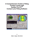
EyeSys System 2000 Software
1-3
Chapter 2
Getting to Know Your System
EyeSys offers two versions of accurate and reliable corneal topography examination
and viewing software. The System 2000 software is used for examinations and
viewing, while the ViewStation software is used for viewing only. Both versions of
the software can operate in a standalone or networked environment.
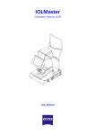
A standalone system would consist of a single computer running the System 2000 or
ViewStation software. A networked system, as shown below, would consist of one
computer running the System 2000 software and one or more computers running the
ViewStation software.
In either case, standalone or networked, the computer running the System 2000
software must have an EyeSys Image Acquisition Unit attached for examinations.
You will find the hardware reliable, precise, and compact, and the software
powerful, customizable, and easy to use. The Primary functions are listed below.
Screen 2-1 Networked System 2000
EyeSys
Corneal Analysis System
2-1
Chapter 2
Primary Functions
♦ Captures a high resolution eye image
♦ Processes the eye image for accurate exam data
♦ Processes exam data into informative color displays
♦ Generates displays to show from 1-5 data maps
♦ Verifies Focus and Automatic Calibration
♦ Exchanges patient data over the Internet with other System 2000 or ViewStation
users.
Additional Functions
In addition the system also has provisions for these functions:
♦ Saving and managing the exam data in an organized database
♦ Exporting and Importing patient data from other EyeSys software versions
♦ Reviewing and analyzing saved exam data
♦ Using the STARS, Holladay Diagnostic Summary, Difference, Four Map
Trend, and 3D Cornea Studio displays.
♦ Setting and changing system parameters
♦ Customizing exam protocols and displays
♦ Contact Lens Fitting
This chapter describes the main parts of your system—the Image Acquisition Unit
and the computer. Chapter 3 discusses the basics of using your system, including
how to use the keyboard and pointing device.
2−2
EyeSys
Corneal Analysis System
Getting to Know Your System
Image Acquisition Unit (IAU)
An Image Acquisition Unit is attached to the System 2000 computer to record the
reflected placido mires on your patient’s cornea. Since the ViewStation software
cannot collect eye examination data, an IAU is not connected to the ViewStation
computer. The IAU features automatic focusing and calibration and consists of four
basic parts:
♦ Videokeratoscope
•
Backlit conical placido disk
•
Three high resolution CCD video cameras
♦ Precision, motorized optical stage manipulator
♦ Precision chin rest assembly
♦ Power base
Computer
The computer required to operate as a System 2000 or a ViewStation consists of the
following components:
♦ Pentium processor
♦ Super VGA color monitor
♦ Internal hard drive
♦ 3½-inch diskette drive
h
Note
Under normal operating conditions, this equipment has
the potential to produce electromagnetic radiation which
may interfere with the proper operation of other
equipment. Avoid the use of this equipment where such
interference will cause other equipment to operate
improperly.
EyeSys
Corneal Analysis System
2-3
Chapter 2
Floppy Diskette
The system floppy drive uses 3½-inch, 1.44-megabyte floppy
diskettes, which can store two patient eye images. The diskettes must
be formatted before use. Refer to “Formatting Floppy Diskettes” in
Appendix C.
System Data Storage
The System 2000 and ViewStation software stores information on the storage drive
of the System 2000 computer. This could be the internal hard drive, removable disk,
or floppy diskette. This table lists the information stored on the system disks:
Internal Hard Drive Contents
System 2000 software
Microsoft Windows software
Patient Directory
Patient Personal Data:
• Name, ID, Sex, DOB
• Physician, Diagnosis
• Referring Party, Group
Patient Exam Data:
• Exam #, Eye, Date, Time
• Volume, Comments
Storage Drive Contents
Patient Exam Data Files:
• Patient Photo
• Eye Image
• Pupil data
• Curvature data
• Side View Eye Image
You can change the drive location of the Storage Drive by referring to “Changing
Data Storage and Backup Options” in Chapter 8.
Normally the Storage Drive is either the internal drive or a removable hard or
optical disk because these drives are capable of storing the large amounts of data
required by the patient exam data files. You can, however, set the Storage Drive to
be a floppy diskette if this fits your requirements.
2−4
EyeSys
Corneal Analysis System
Getting to Know Your System
h
Important
When you perform the various operations in the System
2000 software, it is important that you have the disk
containing the correct patient exam data files inserted
into the Storage Drive.
The patient exam list on the Patient Locator screen lists
the disk volume where the exam is stored. The volume of
a disk is the name or label you assign to the disk. You
should use the volume to organize your patient exam data
files. The volume is added to the disk during formatting.
Refer to Appendix C for information about formatting and
volumes.
Interconnection of Equipment
This equipment is designed for connection only to other components and systems
that have the appropriate medical-grade safety certification for use in a Type B
system in accordance with IEC 601-1-1.
h
Caution
Do not connect this system to any equipment that has
not been evaluated, tested, and certified while connected
to a patient, or while the equipment is in the vicinity of a
patient.
Cleaning of Equipment
It is recommended that the cleaning of the equipment should be done on a periodic
basis. Use a soft cloth or sponge and a disinfectant type of cleaner to wipe the unit
down. Do not spray cleaner into the vent ports on the sides of the power supply
base. Use spectracide, bacterin, or similar product. Follow the directions on the label
and DO NOT immerse the unit in liquid to clean.
EyeSys
Corneal Analysis System
2-5
Chapter 3
Learning the Basics
This chapter covers the basics of using the System 2000 or Viewstation software.
For new computer users, this chapter is especially helpful to get you going quickly
on your new system. This chapter includes the following information:
♦ Your EyeSys software
♦ Using the Screens and Commands
♦ Using Your Keyboard
♦ Powering the System On and Off
♦ Using a Pointing Device
♦ Printing
♦ Using a Joystick
Your EyeSys Software
When started, the software is automatically configured to perform the full
functioning System 2000 or the viewing only Viewstation. The difference between
the two is immediately noticeable as shown by the Main menus below:
Screen 3-1 System 2000 and Viewstation Main Menus
Refer to Appendix for installation instructions.
EyeSys
Corneal Analysis System
3-1
Chapter 3
The EyeSys software operates within the Microsoft Windows environment. It is
designed to minimize your need for software knowledge so you can concentrate on
your patients while performing examinations. This is accomplished by providing
four natural paths to the operation you want to perform. The four main operations
are outlined below:
Patient Examination
The Patient Examination software provides you with all the necessary functionality
to perform the following:
♦ Select an exam protocol
♦ Add exam comments
♦ Capture a patient’s eye image data
♦ Detect the Apex, Rings, and Pupil
♦ View patient exam displays
♦ Print patient exam displays
♦ Save patient exam data
♦ Perform topography based contact lens design for Rigid Gas Permeable
(RGP) lenses
♦ Perform contact lens fitting using a simulated fluorescein map
♦ Print contact lens prescriptions
♦ Select Soft, Soft Toric and RGP lenses from a worldwide database
♦ Review and keep track of the soft lenses you use
Display Patient Data
Display Patient Data allows you to:
♦ Select existing patients and exams from the database
♦ Capture a patient’s photo ID
♦ Review and print patient exam data using different displays such as
STARS, Holladay Diagnostic Summary, Difference, and Four Map Trend
♦ Perform contact lens fitting
♦ View and print corneal data in various 2D and 3D displays (Win 95 only)
♦ Import patient exam data from previous software versions
3−2
EyeSys
Corneal Analysis System
Learning the Basics
System Utilities
With System Utilities you can:
♦ Calibrate the image processing components
♦ Set image processing and display Options
♦ Backup, restore, or rebuild the patient directory
♦ Set data storage and backup options
♦ Perform patient file and directory management
♦ Customize exam Displays, Protocols, and Comments
Data Manager & Communication
The Data Manager and Communication module allows you to:
♦ Sort, delete, edit, or join patient records
♦ Delete, edit, move, or export patient exams
♦ Reprocess exam data
♦ Import patient exam data from previous software versions
♦ Utilize the Internet to export and import all versions of patient exam data
(Win 95 only)
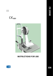
Using Your Keyboard
The keyboard features a standard PC design and
touch that makes data entry fast, efficient, and
comfortable. The software uses these main keys:
Figure 3-2 Keyboard
TAB key – located in the top left quadrant of the keyboard, the TAB key is used to
jump from field to field or from button to button.
SPACE bar – Is used for executing a selected command. For instance, if the TAB key
were used to select a button, the SPACE bar could be pressed to execute that
function.
EyeSys
Corneal Analysis System
3-3
Chapter 3
Arrow keys (cursor keys) – used for moving the cursor or highlight up, down, left,
and right. The cursor indicates your position in a text entry field and takes the form
of a blinking vertical bar. The highlight indicates a selection that you made.
To adjust the keyboard for a comfortable typing angle, turn it over and snap open
the two self-locking legs on the bottom.
Using a Pointing Device
Your system will have either a mouse, trackball, or pen
mouse for pointing to different items on the screens. This
is referred to as your pointing device. The pointing device
offers an efficient means for selecting patients, exams, and
commands.
Figure 3-3 Mouse
As you become proficient with the software, you will find
yourself effortlessly switching back and forth between the
pointing device and keyboard.
Figure 3-4 Trackball
As you move the pointing device, a corresponding movement of an arrow or cursor
occurs on your screen. The following terms are used to instruct the use of the
pointing device:
3−4
EyeSys
Corneal Analysis System
Learning the Basics
Point − means to move the pointing device until the arrow is on
top of the item you want to select.
Click − means to point to the item you want to select and then
press and release the left pointing device button.
Figure 3-5 Pen
Mouse
Drag − means to point to the item you want to select, press and
hold the left button, move the pointing device horizontally or
vertically to select additional adjacent items, and then release the
left button.
Double-Click − means to press and release the left mouse
button twice in rapid succession.
Using a Joystick
The joystick is used to operate the motorized positioning mechanisms of the Image
Acquisition Unit when capturing a patient’s photo ID or eye image.
You can perform four operations by moving the joystick.
The joystick is spring loaded to return it to the center
position when you let go. A description of each operation
follows:
Figure 3-6 Joystick
To move the image left or right, move the joystick in the left or right direction.
To move the image up or down, twist the joystick counter-clockwise or clockwise.
To focus the image, move the joystick to the front or back.
To capture an image, press and release the acquisition button on top of the joystick.
EyeSys
Corneal Analysis System
3-5
Chapter 3
Using the Screens and Commands
You will find the screens in the EyeSys software uncluttered and virtually selfdirecting. Each time you click on a button, the system displays a new screen or
window explaining what is happening. This provides you with positive feedback for
each action you perform within the screen.
Each screen includes a Help button to provide on-line information if you are unsure
about how to proceed. Almost all screens have a Return button that can be used to
go back to a previous screen.
Printing
You may print from two places within the software:
Patient Examination
Refer to “Printing the Display” in Chapter 4 to print a patient display during the
examination process. From this screen you can select portrait or landscape
views, or print to a file.
Display Patient Data
Refer to “Printing the Display” in Chapter 5 to print a patient display while
reviewing stored patient examination data. From this section you can select
portrait, landscape, or print to a file.
Powering the System On
To turn ON the system power, follow these steps:
1. Make sure there is no floppy diskette in the diskette drive.
2. Locate the power switch for the printer and move it to the ON position.
3. Locate the power switch on the transformer and move it to the ON position.
The transformer is a multi-outlet square box that the System 2000 IAU,
computer, and monitor are plugged into. It provides the equipment with isolation
protection from power surges.
3−6
EyeSys
Corneal Analysis System
Learning the Basics
4. Locate the power switch on the computer and move it to the ON position.
5. Allow the system to warm up for five minutes before examining patients. This
ensures that the videokeratoscope’s camera is ready.
Starting the Software
After powering the system ON the computer will start either Microsoft Windows 3.1
or Windows 95.
If you installed the EyeSys software to “automatically run” when Windows
starts, the software will start and display the Main Menu. To begin examining
patients, proceed to Chapter 4, “Patient Examination”.
If you installed the EyeSys software to NOT “automatically run” when
Windows starts, follow the instructions below for the operating system you are
using. After the software starts, the Main Menu will be displayed. To begin
examining patients, proceed to Chapter 4 “Patient Examination”.
Window 3.1
To start the software in Windows 3.1, double-click on the EyeSys System 2000 icon
in the EyeSys System 2000 Program Group, as shown below:
Screen 3-7 EyeSys System 2000 Program Group
EyeSys
Corneal Analysis System
3-7
Chapter 3
Windows 95
To start the software in Windows 95, double-click on the System 2000 icon located
on the desktop, as shown below:
Screen 3-8 EyeSys System 2000 Icon
Powering the System Off
To turn OFF the system power, follow these steps:
1. Save any files and exams, and exit the EyeSys software by returning to the Main
Menu.
2. From the Main Menu, click Exit to return to Windows.
If you are using Windows 3.1, click File in the upper left corner, then click
Exit.
If you are using Windows 95, click Start and then Shut Down., Select Shut down
the Computer and then click OK.
3. Remove and safely store any floppy diskettes from the system. Removable hard
and optical disks should remain in the system.
4. Move the power switch on the computer to the OFF position.
5. Move the transformer power switch to the OFF position.
6. Move the printer power switch to the OFF position.
3−8
EyeSys
Corneal Analysis System
Chapter 4
Patient Examination
After you have turned on the power to the System 2000 and let it warm up for five
minutes, you are ready to perform an examination. The patient should be present
throughout the examination process in case you need to retake the eye image. With a
properly calibrated machine and a little practice, the exam process takes only a few
minutes. This chapter takes you through the following procedures:
♦ Beginning the Exam
♦ Verifying the Rings
♦ Entering Exam Comments
♦ Examining the Pupil
♦ Capturing the Patient’s Eye Image
♦ Viewing the Exam Display
♦ Examining the Apex
♦ Changing Map Options
♦ Verifying Focusing and Processing
♦ Printing the Exam
♦ Retaking the Eye Image
♦ Completing the Exam
Before proceeding with the examination process, you may need to add a new patient
to the patient directory or locate an existing patient. If you are a new System 2000
user, you add all of your patients as new patients at first, but after a while you will
need to look up existing patients.
h
Attention New System 2000 Customer!
You may need to convert patients from your earlier
EyeSys software versions to this version. If you have
patient records in EyeCon, EyeCon+, or DOS software,
refer to “Importing Other Patient Data Types” in Chapter
8 to convert these patients.
You do not have to convert Windows Workstation patient
exams.
EyeSys
Corneal Analysis System
4-1
Chapter 4
Beginning the Exam
To start the examination process, follow the procedures below:
1. From the Main Menu, click on
Patient Examination. The
Examination Protocol Selection
screen appears. Proceed to “Select
the Exam Protocol” below.
The Exit button closes the EyeSys
System 2000 software and returns
you to Microsoft Windows.
Screen 4-1 System 2000 Main Menu
Select the Exam Protocol
2. Click within the Enter/Select
Operator’s Initials box and type
your initials.
If you have previously entered your
initials, click on the down arrow to
the right of the box. A window
appears with a list of initials. Click
on your initials. The window closes
and your initials appear in the box.
Screen 4-2 Examination Protocol Selection
4−2
3. Select which eye to examine by
clicking on one of the following
buttons: OS (left eye), OD (right
eye), or BOTH.
EyeSys
Corneal Analysis System
Patient Examination
On the Protocol Selection screen there are four major buttons that start the
examination protocol of your choice. Examination protocols are the procedures that
the system follows to execute a patient examination. The System 2000 software is
installed with four default exam protocols. They are:
Protocol Name
Single Eye
OD or OS
Display Used
Both Eyes
OD
OS
Axial Map
1. Axial
1. Axial
2. Axial
Shape + Optics
1. Tangential
2. Axial
1. Tangential
2. Axial
3. Tangential
4. Axial
Contact Lens
1. Tangential
2. Numeric
1. Tangential
2. Numeric
3. Tangential
4. Numeric
Overview
1. Axial
2. Tangential
3. Absolute
4. Keratometric
1. Tangential
2. Axial
3. Tangential
4. Axial
h
Note
You can customize exam protocols. You can design your
own or modify and delete any existing protocol by following
the steps in the section “Designing Custom Exam
Protocols” in Chapter 10.
4. Click on the exam protocol you desire. The Patient Directory screen appears.
Proceed to “Entering New Patients” or “Locating Existing Patients” below.
If the protocol name you want is not on one of the protocol buttons, go to
“Protocol Button Assignment” below.
h
Note
The protocol you selected may require you to Select an
Existing Patient, Add a New Patient, or take a Photo ID.
EyeSys
Corneal Analysis System
4-3
Chapter 4
Protocol Button Assignment
Each of the four protocol buttons can be assigned a particular protocol. If you have
designed custom exam protocols and want to assign them to the protocol buttons or
if you want to assign different protocols to the buttons, proceed with the following
steps:
1. From the Examination Protocol Selection screen click on Modify Protocol
Buttons. The Protocol Buttons Setup screen appears.
This screen shows Capture Buttons 1-4.
The buttons are located on the
Examination Protocol Selection screen
(Screen 5-2) as follows:
Capture button 1
Capture button 2
Capture button 4
Capture button 3
Screen 4-3 Protocol Buttons Setup
2. Click on the down arrow next to each protocol button that you want to reassign. A window opens listing the protocols.
3. Click on the protocol that you want to assign to the button. The selected
protocol appears at the top of the window.
4. Click on OK. The Examination Protocol Selection screen reappears with the
protocol buttons reassigned. Go back to step 3 in “Select the Exam Protocol”
above to select an exam protocol.
Entering New Patients
When examining new patients, you will need to take a few moments to enter the
patient's name and ID on the new patient screen and to take the patient's photo ID
using an adapter on the videokeratoscope.
4−4
EyeSys
Corneal Analysis System
Patient Examination
h
A Word About Patient IDs
The Patient ID can be a social security number, billing
account number, or any other patient numbering system
you want to install. The ID can be any combination of
alphanumerical characters no longer than 15 characters.
You may also want to enter additional information to keep in your records about the
patient or the examination, such as male or female, birth date, physician, diagnosis,
referring party, and group.
To enter new patient data and capture the photo ID, follow these procedures:
5. From the Patient Directory screen,
click on New Patient. The Patient
Information screen appears.
Screen 4-4 Patient Directory
EyeSys
Corneal Analysis System
4-5
Chapter 4
6. Enter the new patient's full name and
ID number.
7. Optionally enter the following
information from the table below.
When you type in a new entry, the
system adds it to the list of choices.
Screen 4-5 Patient Information
Optional Information
What to Enter
Sex
Click on Male or Female
Birth date
Enter the patient’s birth date in the same format as
the current date on the screen
Physician
Click on Physician to display choices. Click on your
choice or type the last name of the physician.
Diagnosis
Click on Diagnosis to display choices. Click on your
choice or type the diagnosis.
Referred By
Click on Referred By to display choices. Click on
your choice or type the name of the referring party.
Group
Click on Group to display choices. Click on your
choice or type the group (8 characters only).
8. Click on Save to add the patient to the database. The Patient Photo Capture
screen appears. Proceed to “Taking a Photo ID” below.
4−6
EyeSys
Corneal Analysis System
Patient Examination
Taking a Photo ID
9. Insert the Patient Photo Adapter into
the center of the Videokeratoscope
and position the patient facing the
photo adapter. The patient’s image
will appear on the Patient Photo
Capture screen.
10. Using the joystick bring the patient's
face into focus and press the
acquisition button on top of the
joystick. The Patient Photo Save
screen appears.
Screen 4-6 Patient Photo Capture
11. If the patient's photo is acceptable,
click on the Save Image button. The
Exam Comments screen appears
(Screen 5-7).
If the photo needs to be
recaptured, click on the Retake
button and repeat step 2.
Screen 4-7 Patient Photo Save
To bypass taking the photo ID,
click the Skip Photo button. You can
add the photo later, if desired. Refer
to “Taking the Patient’s Photo ID”
in Chapter 8.
You are now ready to proceed with the examination. Go to “Entering Exam
Comments” below.
Locating Existing Patients
When examining patients who have already been added to the patient database, you
will need to locate their current records before proceeding with the examination. You
can locate a patient by last name or patient ID.
EyeSys
Corneal Analysis System
4-7
Chapter 4
h
A Word About the Patient’s Photo ID
If you insert the disk that has the patient’s data file and
photo ID, the photo ID will be displayed on the Patient
Directory screen when the patient is selected.
If using a new disk for an existing patient, you will have to
recapture the photo ID and save it to the new disk. Refer
to “Taking the Patient’s Photo ID” in Chapter 8.
To Locate a Patient by Last Name:
1. On the Patient Directory screen, enter the patient's last name.
As you type, the system will highlight the first name in the list that matches
what you type.
2. If the desired patient is not highlighted, click the pointing device on the patient
to be examined. If you have a large database, you may have to scroll through the
list of names before locating the patient.
When the desired patient is highlighted, click on the OK button. The Exam
Comments screen appears (Screen 5-7).
You are now ready to proceed with the examination. Go to “Entering Exam
Comments” in Chapter 5, “The Examination Process.”
To Locate a Patient by Patient ID:
1. On the Patient Directory screen, enter the patient's ID number.
As you type, the system will resort the directory and highlight the first number
that matches what you type.
2. If the desired patient is not displayed, repeat step 1 or scroll through the list of
patients.
When the desired patient is highlighted, click on the OK button. The Exam
Comments screen appears (Screen 5-7).
You are now ready to proceed with the examination. Go to “Entering Exam
Comments” below.
4−8
EyeSys
Corneal Analysis System
Patient Examination
Entering Exam Comments
If the exam protocol chosen above includes the exam comments option, the Exam
Comments screen appears. The Exam Comments screen is used to enter comments
about the examination, such as exam type, prescription information, diagnosis, and
more. These comments are displayed on the:
♦ Exam listing of the Patient Locator screen (Screen 6-1) when you display
patient data
♦ Patient File Management screen (Screen 8-3) when you perform file
management
♦ Bottom of the exam data displays
The comments are a good tool to help you quickly locate a particular exam for a
patient. This section describes how to enter exam comments.
h
Note
You can enter exam comments later, if desired. Refer to
“Edit Patient Exam Data” in Chapter 8.
If you do not want to add
comments now, click on the Skip
This Step button and continue with
“Capturing the Patient's Eye Image”
below.
The Exam Comments screen provides
two methods for entering comments:
Screen 4-8 Exam Comments
♦ Point-and-click (default) − EyeSys provides built-in comments you can point to
with your pointing device and click to enter automatically.
♦ Keyboard method − Type your own comments.
EyeSys
Corneal Analysis System
4-9
Chapter 4
Note
h
You can design your own custom comments that use
the point-and-click method. Refer to “Designing Custom
Comments” in Chapter 11.
Point-and-Click (Default)
To enter default comments provided by EyeSys using the point-and-click method,
follow these steps:
1. Click on the desired options to enter information in the comments box. A table
of default comments and corresponding ranges follows:
Comment Type
Comment
Range
Time Period
days
weeks
months
years
0 to 999
0 to 999
0 to 999
0 to 999
Procedure Descriptor *
pre-op
post-op
pre-enhance
post-enhance
pre-suture rem
post-suture rem
None
Procedure Performed *
RK
AK
RK/AK
Cataract
PKP
PRK
RGP
SCL
Corneal Scar
None
Continued on the next page
4−10
EyeSys
Corneal Analysis System
Patient Examination
Comment Type
Comment
Range
Refraction Types
Man. Rx
Cyclo. Rx
Spec. Rx
Auto. Rx
None
Refraction
Measurements
Rx Sphere
Rx Cylinder
Rx Axis
Vertex Distance
+20.0 to -20.0
+20.0 to -20.0
0° to 180°
7 mm to 19.5 mm
Visual Acquity *
VAcc
20/10 to 20/400
HM,LP
20/10 to 20/400
HM,LP
VAsc
* These comments may be customized, refer to Chapter 11.
2. To delete comments, do one of the following:
•
Place the cursor at the beginning of the data to be deleted and drag the
cursor to the end of the data to be deleted, and press Delete.
•
Click Erase at any time to clear the comments box.
When the comments are acceptable, click on the Save & Continue. The
Capture Eye Image screen appears.
Keyboard Method
To enter comments by typing, do the following:
1. Click within the comments box and type the desired comments.
2. To erase comments, use the BACKSPACE key to delete information or click on
the Erase button to clear the comments box and start over.
When the comments are acceptable, click on the Save & Continue. The
Capture Eye Image screen appears. Proceed to “Capturing the Patient’s Eye
Image” below.
EyeSys
Corneal Analysis System
4-11
Chapter 4
Capturing the Patient's Eye
Image
h
Note
Insert the proper disk containing the patient exam data
files before starting this procedure.
Capturing quality eye images and preserving patient confidence requires that the
patient be relaxed and comfortable in front of the video-keratoscope. Accurate
surgical planning and diagnoses relies on proper centering and focus of the eye
image.
Position the patient and take the eye image as follows:
1. Place the patient's forehead against the forehead rest with the chin resting
comfortably on the chin rest. Raise or lower the chin rest if necessary.
2. Turn the head slightly so that the eye being captured faces the videokeratoscope
directly. This eliminates nose shadow.
3. Have the patient do the following:
•
Keep both eyes open during the procedure. If the patient has difficulty
maintaining both eyes open, an assistant should hold the patient's upper
eyelid open with a cotton swab being careful not to touch or apply any
pressure to the cornea. You may also use an occluder to cover the eye not
being examined.
•
Fixate on the green flashing light in the center of the placido rings. If the
patient has difficulty fixating on the green light, place an eyepatch over the
eye not being examined.
4−12
EyeSys
Corneal Analysis System
Patient Examination
4. Watch your monitor. A continuous
video image of the patient's eye is
displayed as shown.
5. Using the joystick, adjust the
image until the pupil is centered in
the centering box.
6. Using the joystick, adjust the
focus until the blue line is centered
horizontally (even with the
centering marks) within the green
box.
Screen 4-9 Capture Eye Image
For more information on using the joystick, refer to Chapter 3.
7. Press the acquisition button on top of the joystick. The system will capture the
eye image. Proceed to “Examining the Apex” below.
If the patient is unable to remain motionless for the length of time it takes to
focus perfectly, press the spacebar to capture the image when the focus is
optimal. The system will capture the eye image and correct for small, out-offocus conditions. Proceed to “Examining the Apex” below.
h
Note
The system focuses the eye image automatically for
precise repeatable results.
EyeSys
Corneal Analysis System
4-13
Chapter 4
Examining the Apex
The operator should examine the detected apex for possible editing or even retaking
the image.
1. Look at the detected apex. You
should find a red square located on
edge of the apex.
If the square is not located on the
edge, perform step 2 to edit the
apex.
If the square is located properly,
proceed to step 3.
Screen 4-10 Apex Verification
2. Click on Edit. Point to the red square and click and hold the left pointing device
button. Move the red dot so that it intersects the apex at the center of the eye,
then release the pointing device button.
3. Click on Accept. The system processes the eye image, locates the rings, and
displays the results on the Focusing and Processing Verification screen.
IF A WARNING MESSAGE APPEARS DURING PROCESSING:
The system may have trouble processing a center point if the patient's cornea is very
distorted or the center ring mire is very small. In this case, a warning message
window appears alerting the operator to this difficulty. If this happens, perform the
following procedure:
1. Click OK on the Warning window. A pencil appears on the screen.
2. Using the pointing device, position the point of the pencil on the center of the
image and click the left button.
Result: The system reprocesses the eye image, locates the rings, and displays
the results on the Focusing and Processing Verification Screen. Continue with
the next section, “Verifying Focusing and Processing” below.
4−14
EyeSys
Corneal Analysis System
Patient Examination
Verifying Focusing and Processing
At this point, the operator should
examine the resulting rings and pupil
for possible editing or even for retaking
the image. You should do this with the
patient present in case you need to
retake the eye image. Once you've done
it a few times, this procedure only takes
about one minute.
Screen 4-11 Focusing and Processing
Verification
Focusing and Centering Guidelines
Before examining the rings, make sure that the system found the proper center and
that the eye image is in proper focus. Check the image as follows:
•
Make sure the center was found by checking the red dot. It should be placed in
the center of the red and yellow rings. The red dot should not be outside of the
innermost placido mire.
•
Make sure the red and yellow concentric rings alternate. The red rings should be
located on the outer edge of the black rings and the yellow rings should be
located on the outer edge of the white rings.
If any of these visual checks look wrong, the eye image should be retaken. Go to
“Retaking the Eye Image” below.
If the visual checks are acceptable, go to “Verifying the Rings” to examine the
rings for possible editing. It is not necessary to edit every eye image.
EyeSys
Corneal Analysis System
4-15
Chapter 4
Retaking the Eye Image
If you need to recapture the eye image, follow these steps:
1. From the Focusing and Processing Verification screen, click on Retake. The
Contrast Level screen appears.
2. Click on the large arrow buttons to
adjust the contrast level towards the
patient’s eye color. As you click on
the arrow button, the pointer at the
bottom of the screen moves in the
direction of the arrow. Blue eyes
should be adjusted until the pointer
is at 2. Other eye colors should be
adjusted to be in the range of 4-12.
Screen 4-12 Contrast Level
This adjustment changes the value of the edge threshold located on the Image
Processing Options screen (Screen 8-12.)
3. After adjusting the contrast level, click on OK. The Capture Eye Image screen
reappears.
4. Repeat “Capturing the Patient’s Eye Image,” “Examining the Apex,” and
“Verifying Focusing and Processing.”
4−16
EyeSys
Corneal Analysis System
Patient Examination
Verifying the Rings
1. Examine the rings on the Focusing and Processing Verification screen. Look for
any of these conditions:
•
Check if any rings or data points extend into areas of brow or nasal
shadow. These may need to be removed.
•
Check for a limbal line. If the system picked up a limbal line, it will appear
as a ring detected at the outer edge of the eye image. This is not a valid ring
and should be removed.
•
Check for critically incomplete rings. These should be reconstructed.
2. If the rings need editing, continue with step 3.
If these visual checks are acceptable, you do not need to edit the rings. Click
on Accept. The system reprocesses the eye image and displays the pupil on the
Pupil Verification screen. Go to the next section, “Examining the Pupil.”
3. Click Edit on the Focusing and Processing Verification screen. The Processed
Ring Editor screen appears.
4. To add ring data points with the
arrow tip, point to where ring
points should be added and drag the
pointing device.
To erase points, point to the ring
points that need to be removed and
drag the pointing device.
Release the button when finished.
Screen 4-13 Processed Ring Editor
5. When editing is complete, click the Finished button. The Focusing and
Processing Verification screen re-appears.
6. Re-examine the processed rings.
If more editing is required, click the Edit button and repeat the editing process
(steps 1-6).
EyeSys
Corneal Analysis System
4-17
Chapter 4
If the eye image looks properly captured and processed, click the Accept
button. The system processes the eye image and displays the pupil on the Pupil
Verification screen. Proceed to “Examining the Pupil” below.
Examining the Pupil
During the final step of capturing an eye image, the system performs pupil detection.
If the pupil is smaller than 0.5 mm or is extremely irregular, the system may have
trouble locating the pupil. In this case, the following message appears:
If you want the system to use a
standard 3 mm pupil centered 0.2 mm
temporally from the ring mire center,
click on Yes and continue with step 1
below.
If you want the system to discard the pupil and save no pupil data, click on No
and proceed to “Viewing the Exam Display” below.
1. Check the pupil contour to make
sure it is accurately located on the
inner edge of the visible iris.
If the contour missed part of the
pupil edge, either because of poor
lighting or a very irregular pupil
(i.e., iridectomy) then it will have to
be edited. Continue with step 2.
Screen 4-14 Pupil Verification
If the pupil image looks properly
captured and processed, skip to
step 7.
2. Click the Edit button. The Pupil Editor screen appears.
4−18
EyeSys
Corneal Analysis System
Patient Examination
When the Pupil Editor screen appears,
you will notice a red cross located
outside the pupil contour at zero
degrees (three o’clock.) You can drag
the red cross to change the shape of the
pupil contour. As you drag the red
cross, you will notice the pupil contour
rubber-banding to match your
movements.
Screen 4-15 Pupil Editor
3. Move the red cross until the pupil contour lies on the edge of the pupil. The
pupil contour will move along with the red cross.
4. Release the left pointing device button when the contour is in the correct
position. The red cross will advance by 45 degrees counter-clockwise around the
angular scale.
5. Repeat steps 3-4 until the red cross has gone a full 360 degrees.
6. Click on Finished. The Pupil Verification screen reappears.
If more editing is required, click the Edit button and repeat the editing process
(steps 3-6).
If you are dissatisfied with the pupil, click the Discard button to abandon the
pupil and proceed to “Viewing the Exam Display” below. The system abandons
the pupil and saves none of its data.
When editing is complete, continue with step 7.
7. Click on Accept when you are satisfied with the pupil image.
The next screen depends on whether or not you are finished with the
examination process:
If you are examining both eyes, the system returns to the Exam Comments
screen. Refer to "Entering Exam Comments" above and repeat the process for
the second eye.
If you are finished with the exam, the Exam Display appears. Go to “Viewing
the Exam Display.”
EyeSys
Corneal Analysis System
4-19
Chapter 4
Viewing the Exam Display
On Exam Displays that contain a map image, a special function is available to help
you examine the data. This special function, Crosshair Data, is described below:
Crosshair Data
You will notice a cross located at the detected center of the eye and a box of data in
the lower right of the screen. The data corresponds to the center of the cross as
follows:
♦ Power (PWR) in diopters
♦ Radius (RAD) in millimeters
♦ Distance to the center (DIS) in millimeters
♦ Axis in degrees
You can move the cross to examine data in different parts of the image, as described
below:
1. Point to the cross and drag the
pointing device.
2. While holding the button down,
move the cross to the desired
position in the eye. As you move
the cross, the data in the lower
right of the screen changes to
reflect measurements at the new
location.
Screen 4-16 Exam Display
Before clicking on Done/Save/Print to end the examination, you can click on
Options to change display options such as map types, map layers. Go to “Changing
Map Options” below.
If you are finished viewing the display, click on Done/Save/Print. The Print
Options screen appears. From the Print Options screen you have the option of
printing the display or skipping the printing process entirely. Go to “Printing the
Exam” below.
4−20
EyeSys
Corneal Analysis System
Patient Examination
h
Note
The system saves the exam data and eye image when you
click Done/Save/Print.
Changing Map Options
Follow these procedures to select map options for customizing the Exam Display:
1. From the Exam Display click
the Options button. The Map
Options screen appears.
Screen 4-17 Exam Display
2. Click the desired Map Type.
If you change your mind, just
click on another Map Type.
Only one Map Type can be
selected at a time.
For descriptions of Map Types,
refer to Appendix B.
Screen 4-18 Map Options
3. Select each Layer you want to display on the Data Map. Multiple layers can be
displayed concurrently. For descriptions of Map Layers, refer to Appendix B.
EyeSys
Corneal Analysis System
4-21
Chapter 4
4. Click on the square box next to Interpolate if you want the system to fill in black
areas or holes in the Axial Map Display. The system will interpolate across
areas of missing data. However, the system will not display areas that are not
surrounded by data.
5. Click on the square box next to Smooth Pattern if you want to view the color
maps with less resolution. This will help extract the relative pattern from the
display and reduce the granularity.
6. If you selected the Axial, Threshold, Refractive, or Tangential map types,
you can change the color scale range. The normalized color scale range in the
data maps can be changed to a specific range. The parameters are the middle
value and the color step size. There are 15 colors to work with.
To change the color scale range, click within the Middle Value box and Step
Size box and type new values. A new color scale range will be defined.
Example: If the Middle Value is 42 diopters and the Color Step Size is 1
diopter, then the range covered by 15 colors would be 35 to 49 diopters.
7. If you selected the Profile or Tabular map types, you can change the map
axis of the flattest and steepest meridian.
If you selected the Threshold map type, you can change the high and low
thresholds.
8. When finished selecting Map Options, you have two choices:
To save the changes and go back the Exam Display, click on Save. The Exam
Display reappears with the selected map type and layers.
To cancel the changes and go back to the Exam Display, click on Cancel. The
Exam Display reappears without changing the map options.
9. If everything on the Exam Display looks acceptable, click the
Done/Save/Print button. The Print Options screen appears. From the Print
Options screen you have the option of printing the display or skipping the
printing process entirely. Go to “Printing the Exam” below.
If the Exam Display is unacceptable and you want to perform a new
examination, click Cancel. The current data will not be saved and you will need
to repeat the examination process. The Exam Complete screen appears. Go to
“Completing the Exam” below.
4−22
EyeSys
Corneal Analysis System
Patient Examination
Printing the Display
Use the Print Options screen to print a hard copy of the exam display or to copy the
exam display to a file. If you copy to a file, the data normally sent to the printer will
be stored in the disk drive and filename you provide. The file will be stored in
“.BMP” (bitmap) format.
1. Select Printer or Print to a File in
the Print To box.
If you do not want to print at this
time, deselect both Printer and File
in the Print To box.
Screen 4-19 Print Options
2. Click on Printer Setup to select the printer or paper size, source, and orientation.
Portrait provides a vertical page orientation. Landscape provides a horizontal
page orientation.
EyeSys
EyeSys
Portrait
Landscape
3. Click on OK. The Print Options screen reappears.
4. Click on Done. The exam display is printed, sent to a file, or saved with no print
action taken. After the chosen action is performed, The Exam Complete screen
appears. Go to the next section, “Completing the Exam.”
If you click Cancel, the exam display is not saved.
EyeSys
Corneal Analysis System
4-23
Chapter 4
Completing the Exam
The Exam Complete screen provides several options depending on what action you
intend to take.
Use the table below to determine your
next step:
Screen 4-20 Exam Complete
If you...
Are finished with this patient
and there are no other patients
to be examined
Are finished with this patient
but want to examine a
different patient
Want to examine the patient's
other eye or retake the eye
image
Want to change the display
type or perform contact lens
fitting
4−24
Click on
Return to Main
Menu
Result
The Main Menu appears
(Screen 5-1).
Next Patient
The Examination Protocol
Selection screen appears
(Screen 5-2).
The Exam Comments
screen appears
(Screen 5-7).
The Select Display screen
appears
(Screen 6-2).
OD or OS button
Display
EyeSys
Corneal Analysis System
Chapter 5
Display Patient Data
This chapter describes how to review, change, and print exam displays. The
following tasks are included:
♦ Selecting an EyeSys System 2000 Software patient to review
♦ Selecting an Exported, EyeCon+, EyeSys DOS, or EyeCon patient to review
♦ Selecting a single exam or group of exams to display
♦ Selecting exam displays
♦ Changing data map options
♦ Printing the display
Selecting EyeSys Patients
An EyeSys patient is a patient whose examination data was saved in the System
2000 Software patient exam data files. To view patient exam data files saved by a
previous software version or any exported exam data files, skip to “Selecting Other
Patient Data Types.”
h
Note
Make sure you insert the proper disk containing the
patient exam data files before starting this procedure.
1. From the Main Menu, click on Display Patient Data. The Patient Locator screen
appears.
EyeSys
Corneal Analysis System
5-1
Chapter 5
2. Select a patient from the Patient
Locator screen or locate a patient
using one of the methods below.
When a patient is selected, a list of
the patient’s exams appears at the
bottom of the screen.
If the patient’s photo ID was
previously captured, it will be
displayed.
Screen 5-1 Patient Locator
To Locate a Patient by Last Name:
3. On the Patient Locator screen, enter the patient's last name. As you type, the
system highlights the first name in the list that matches what you type.
4. If you have a large database, you may have to scroll through the list of names
before locating the desired patient.
When the patient is highlighted, a list of the patient’s exams appears at the
bottom of the screen and the photo ID appears if it was previously captured.
Continue with “Selecting Exams” later in this chapter.
To Locate a Patient by Patient ID:
1. On the Patient Locator screen, enter the patient's ID number. As you type, the
system displays patient ID numbers and highlights the first number that matches
what you type.
2. If the desired patient is not displayed, repeat step 1 or try to locate the patient
by last name.
When the patient is highlighted, a list of patient exams appears in a box at the
bottom of the screen and the photo ID appears if it was previously captured.
Continue with “Selecting Exams” later in this chapter.
5−2
EyeSys
Corneal Analysis System
Display Patient Data
Selecting Other Patient Data Types
Follow these procedures to view patient exam data files that were exported or saved
with a previous EyeSys software version (EyeCon+, EyeCon, or EyeSys DOS). You
can retrieve these files from a local drive, network drive, or any System 2000
connected to the Internet through an Internet Service Provider. EyeSys DirectNet is
the easiest way to import patient data files from the Internet. However, if the sender
does not have access to DirectNet, standard email software can be used to transfer
files. Refer to Chapter 9, for information on DirectNet. Follow the topic below that
fits your situation.
Local and Network Drives
h
Note
Before starting this procedure, make sure you insert the
proper disk containing the patient exam data files.
1. From the Main Menu, click on Display Patient Data. The Patient Locator
Screen appears.
2. Click on Other EyeSys Patient Types. The Other EyeSys Patient and Exams
screen appears as shown in
2. Click within the radio button next to
Source Disk Drive. A black dot
appears indicating that the source is
a local or networked drive.
3. Click within the Disk Drive box and
then click on the drive letter you
want from the drop down menu that
appears. Patients from the drive you
selected are listed under Patient and
Exam Data on the right hand side.
Screen 5-2 Other EyeSys Patients and Exams
4. Click on the desired patient. The patient’s exams are displayed in the exam box
at the bottom of the screen.
Continue with “Selecting Exams” below.
EyeSys
Corneal Analysis System
5-3
Chapter 5
Selecting Exams
When you locate a patient, a list of exams appear. You can select either a single
exam or group of exams to review:
1. Click on each exam you desire. Each exam you click on will stay highlighted.
You can select up to four exams.
If you need to deselect an exam, click on the highlighted exam.
2. Verify that the Drive box contains the correct drive letter (i.e., floppy diskette,
removable hard disk, internal hard disk, or optical disk) for the exams you
selected. If it does not, click on the correct drive letter.
3. Click Display. The Select Display screen appears.
4. Go to “Selecting an Exam Display” below.
Selecting an Exam Display
Exam displays are a convenient way of showing patient exam data on one or more
data maps. There may be up to five data maps on each display. Each data map can
be a particular type with different layers turned on or off. EyeSys provides fourteen
default displays for you to work with.
This procedure begins at the Select Display menu, which appears after locating the
patient and selecting one to four exams.
From the Select Display menu you can:
•
Display patient exam data
•
Modify button titles to change the
type of display activated
•
Start contact lens design
Screen 5-3 Select Display
5−4
EyeSys
Corneal Analysis System
Display Patient Data
To display patient exam data, go to “Displaying Patient Exam Data” below.
To modify which displays are activated by the buttons, follow the procedures in
the next section.
Modifying Display Button Titles
The Select Display screen shows six Map buttons. You can change which displays
are activated by these buttons by following this procedure:
1. From the Select Display screen, click on Modify Map Buttons. The Map
Buttons Setup screen appears.
2. The map button numbers on this
screen correspond to the map buttons on
the Select Display screen, as follows:
Map button 1
Map button 2
Map button 3
Map button 4
Map button 5
Map button 6
Screen 5-4 Map Buttons Setup
3. Determine which map button you want to change. Click on the corresponding
down arrow button. A window of different map types appears. Click on the Map
Type you desire.
4. Repeat step 2 to change another button. When finished changing buttons, click
on Return to Select Display Menu. The Select Display screen reappears with the
buttons reassigned. Continue with “Displaying Patient Exam Data” below.
EyeSys
Corneal Analysis System
5-5
Chapter 5
Displaying Patient Exam Data
On Exam Displays that contain a map image, a special function is available to help
you examine the data. This special function, Crosshair Data, is described below:
Crosshair Data
You will notice a cross located at the detected center of the eye and a box of data in
the lower right of the screen. The data corresponds to the center of the cross as
follows:
♦ Power (PWR) in diopters
♦ Radius (RAD) in millimeters
♦ Distance to the center (DIS) in millimeters
♦ Axis in degrees
You can move the cross to examine data in different parts of the image, as described
below:
1. Point to the cross and drag the pointing device.
2. While holding the button down, move the cross to the desired position in the eye
image. As you move the cross, the data in the lower right of the screen changes
to reflect measurements at the new location.
Display Patient Data
To display patient exam data, follow the procedures below:
1. Click on a display name from the Select Display screen. The selected display
appears.
Example: If you select Four Map Overview from the Select Display screen, you
can see four maps at once. An example of a Four Map Overview is shown:
5−6
EyeSys
Corneal Analysis System
Display Patient Data
Screen 5-5 Four Map Overview Display
2. After viewing the display, choose an action from the following table:
If you want
to...
Action
Result
Change map
options
Click on Options.
Go to “Changing Map
Options” below.
The Display Options
(Screen 6-6) or the Map
Options (Screen 6-7)
screen appears.
Print the
display
Click on Print.
Go to “Printing the Display”
in this chapter.
The Print Options
screen appears (Screen
6-8).
Exit
Click on Done.
Select another display or exit
to the Main Menu.
The Select Display
screen reappears
(Screen 6-3).
EyeSys
Corneal Analysis System
5-7
Chapter 5
Changing Map Options
You can change map options such as map types, map layers, or exams for each map
on the display.
Refer to Appendix B for detailed information about map types and layers.
If you are viewing a multi-map display and click Options, the first screen to appear
is the Display Options screen. This screen is used to select which map you want to
change.
If you are viewing a single map display, the first screen to appear is the Map
Options screen. Proceed to step 2 below.
The procedures below describe how to change map options for a Four Map
Overview display.
After clicking Options from the Four Map Overview display, the Four Map Display
Options screen appears.
1. Click on the Options button next to
the map you want to change. The
Map Options screen appears.
Screen 5-6 Four Map Display
5−8
EyeSys
Corneal Analysis System
Display Patient Data
2. Select a Map Type by clicking
within the small circle next to the
name you want.
Map types are described in
Appendix B, “Topographic Data
Displays.”
3. Select one or more Map Layers by
clicking within the small box next to
the name you want.
Screen 5-7 Map Options
Map layers are described in Appendix B, “Topographic Data Displays.”
4. Click on the square box next to Interpolate if you want the system to fill in black
areas or holes in the color map display. The system will interpolate across areas
of missing data. However, the system will not display areas that are not
surrounded by data.
5. Click on the square box next to Smooth Pattern if you want to view the color
maps with less resolution. This will help extract the relative pattern from the
display and reduce the granularity.
6. If desired, change the color scale range. The normalized color scale range used
in the data maps can be changed to a specific range. The parameters for
controlling the range are the middle value and the color step size. There are 15
colors to work with.
To change the color scale range, click within the Middle Value box and Step
Size box and type new values. A new color scale range will be defined when you
go back to the Exam Display screen.
Example: If the middle value is 42 diopters and the step size is 1 diopter, then
the range covered by 15 colors will be 35 to 49 diopters.
7. If desired, change the exam associated with this data map. The box in the upper
right of the screen displays the exams you selected for the currently viewed
patient. To change exams, click on the desired exam. Refer to “Selecting
Exams” earlier in this chapter for additional information.
EyeSys
Corneal Analysis System
5-9
Chapter 5
8. When you have chosen all the options you want, click on Save to implement
the changes and return to the Map Display screen.
To return to the Map Display screen without making changes, click on
Cancel.
9. Repeat steps 1 - 7 for each map you want to change. When you are finished
changing map options, go to step 9.
10. From the Four Map Display screen, click Save. The Four Map Overview
display reappears with the map options you selected.
11. Go back to the table on page 6-8 to determine your next action.
Printing the Display
You can print a hard copy of the display data or print to a file. If you print to a file,
the data normally sent to the printer will be stored on the disk drive in a filename
you provide. The file will be stored in “.BMP” (bitmap) format. To print the display
currently being viewed, follow these procedures:
1. From the Map Display screen, click
on Print. The Print Options screen
appears.
2. Select Print to the Printer or Print
to a File.
If you do not want to print at this
time, deselect both Printer and File
in the Print to box.
Screen 5-8 Print Options
5−10
EyeSys
Corneal Analysis System
Display Patient Data
3. Click on Printer Setup to select the printer or paper size, source and orientation.
Portrait provides a vertical page orientation. Landscape provides a horizontal
page orientation.
EyeSys
EyeSys
Portrait
Landscape
4. Click on OK. The Print Options screen reappears.
5. Click on Done. The Display screen reappears and the exam display is printed or
sent to a file.
6. Go back to the table on page 6-8 to determine your next action.
STARS Display
The Standard Topographical Analysis for Refractive Surgery (STARS) display
provides a retrospective view of the cornea and helps in analyzing surgical results
while tracking the healing process.
To view a STARS display, you must select a pre-op, post-op, and follow-up exam.
An example of the STARS display follows:
EyeSys
Corneal Analysis System
5-11
Chapter 5
Screen 5-9 STARS Display
The STARS display shows the pre-op, post-op, and follow-up data maps at the top
and the Surgical Change and Healing Change difference maps at the bottom. Some
characteristics of the STARS display are:
•
A single, standard scale is used for all examinations.
•
The difference map scales are optimally adjusted and centered on the mean
difference in central “K” values.
To print the STARS display, click Print and follow the procedures in “Printing the
Display” above.
To change map options, click on Options and follow the procedures in “Changing
Map Options” above.
To go back to the Select Display screen, click on Done. The Select Display screen
reappears (Screen 6-2).
5−12
EyeSys
Corneal Analysis System
Display Patient Data
Difference Display
The Difference Map is an adjustable map of corneal curvature which is derived by a
subtractive analysis of two examinations. The map is used to analyze changes in the
corneal curvature over time. The difference scale is centered on 0.0 diopters and
utilizes 0.5 diopter steps.
An example of the Difference Display follows:
Screen 5-10 Difference Display
Four Map Trend Display
The Four Map Trend Display shows a historical sequence of patient exams using
color maps. Four sequential exams of one eye or two exams of each eye can be
shown.
An example of a Four Map Trend Display is shown below:
EyeSys
Corneal Analysis System
5-13
Chapter 5
Screen 5-11 Four Map Trend Display
3D Cornea Studio Display
The 3D Cornea Studio Display displays the Corneal data in a variety of 2dimensional (2D) and 3-dimensional (3D) views. Dragging the mouse over the data
yields local numeric information about the cornea, such as curvature, sagittal height,
and semi-meridian eccentricity values. In 3D view, the cornea can be rotated via onscreen controls.
In both 2D and 3D views, the following maps and corresponding numeric legends
can be viewed:
•
Axial Radius of Curvature
•
Sagittal Height
•
Sagittal Height Difference from a Reference Surface
5−14
EyeSys
Corneal Analysis System
Display Patient Data
An example of the 3D Cornea Studio displaying a 3D wire frame of sagittal height
difference from an aspherical reference surface is shown below:
Screen 5-12 3D Cornea Studio
3D Cornea Studio Main Screen Controls
You can use the following controls to change the way corneal data is displayed on
the 3D Cornea Studio display. Each control is explained below.
3D Position Controls
Located in the upper right of the display, these controls allow the user to position the
cornea in any spatial orientation. There are two types of controls, buttons and
spinners. The spinners allow direct specification of the display orientation angles, in
5 degree increments. The range is -90 to 90 degrees in each direction. The buttons
allow viewing the cornea in the following pre-determined positions:
EyeSys
Corneal Analysis System
5-15
Chapter 5
♦ FRONTAL—presents the data in frontal view
♦ SLANT—presents the data in a slanted view
♦ Hor. Prof.—presents the data from the side, with the cornea "pointing" upwards,
in sag view. In delta sag view, the plot points upward if the cornea is steeper
than the reference surface and downwards otherwise.
♦ Vert. Prof.—presents the data from the side, with the cornea "pointing" to the
right, in sag view. In delta sag view, the plot points to the right if the cornea is
steeper than the reference surface and to the left otherwise.
Show 3D / 2D Toggle Button
Located in the lower left, this button instantly redisplays the cornea in a 2D or 3D
format.
Color=Curv./Color=Sag Toggle Button
This button instantly redisplays the cornea using color information according to the
following legend:
♦ Sagittal View—the map's color represents sagittal height. Blue is flattest, red is
steepest, with respect to the corneal Apex plane.
♦ Sagittal Difference View—the map's color represents sagittal height difference
from the reference surface. Blue is where the cornea is flattest with respect to
the reference surface (above), and red is steepest (below). Note that the corneal
and reference surfaces are registered at the corneal apex.
♦ Curvature View—the map's color represents corneal curvature. Blue is flattest
and red is steepest. Note that the legend can be displayed in Diopters, or mms.
Recalc Button
In 2D View, you must click this button to redisplay the data, if you make changes to
the Reference Surface subtraction parameters. Otherwise, it redraws the same map.
In 3D View, the Recalc button is inoperative, since the data is redrawn
automatically after every parameter change.
5−16
EyeSys
Corneal Analysis System
Display Patient Data
Reference Surface Subtraction
If the Ref. Surface Sub checkbox, located in the lower right, is selected, and the
Color mode is Sagittal, then the map displayed represents the sagittal height
difference between the cornea and a standard aspheric surface (an elliptical surface)
where:
Z=
− X*X
BC + BC * BC − (1 − E * E ) * X * X
When this data is first displayed, the base curve of the reference surface is made
equal to the cornea's central curvature on the first ring at the zero-degree meridian,
and its eccentricity is set to that of the cornea's horizontal semi-meridian.
The user can alter the Base curve and eccentricity of the reference surface via the
spinner (arrow) controls.
The user can also alter the scale factor in the Z direction, via the Z-scale slider
control. This helps magnify the “Surface Detail”, by scaling the data in the Z
direction with a scale factor that is proportionately larger than in the X-Y directions.
This relative scale factor is the number displayed above the slider control. This is
called asnisotropic plotting.
For Example: If the scale factor is 10, then the data is amplified by a factor of 10
along the Z dimension, with respect to the X-Y dimensions, so that
1mm in the X or Y dimension (grid square) corresponds to 0.1mm in
the Z direction.
Note that a positive delta Sag value at a particular point in the corneal vertex plane
means that the corneal surface is above the reference surface.
EyeSys
Corneal Analysis System
5-17
Chapter 5
Setting Program Options
This dialog is invoked with a right mouse click, and allows the user to permanently
alter the following settings:
♦ Use Diopters, instead of mm for the curvature map. If this is selected, the
numbers on the color legend represent axial curvature in Diopters. Otherwise,
the radius of curvature in mm is displayed.
♦ Display mm Grid. When selected, this displays a mm grid in either 3D or 2D
views. In 3D view, the grid is always parallel to the Corneal vertex plane. In
sagittal display mode, the grid is at a distance of 1.7 mm below the cornea
vertex (towards the retina). In sagittal difference mode, the grid is in the Corneal
vertex plane.
5−18
EyeSys
Corneal Analysis System
Chapter 6
Pro-Fit™ Contact Lens Fitting
This chapter describes the basic procedures on how to use the EyeSys System 2000
Pro-Fit Contact Lens Fitting Software.
For more detailed information about contact lens fitting, refer to the booklet Contact
Lens Fitting with the EyeSys System 2000 Pro-Fit Software by Beth A. Soper, that
was included with your system. The following topics are covered in this chapter:
♦ Accessing and Starting Contact Lens Fitting
♦ Fitting Soft Contact Lenses
♦ Trial Fitting Soft Lenses
♦ Ordering Soft Lenses
♦ Fitting RGP Lenses
♦ Using the Simulated Fluorescein Procedure
♦ Ordering RGP Lenses
♦ Tracking Soft Lens Usage
♦ Clinic Name, Address, and Telephone Number
The first two sections of this chapter explain how to access contact lens fitting and
update your contact lens database. If you are already familiar with these actions,
proceed to “Starting Contact Lens Fitting” below.
Accessing Contact Lens Fitting
Contact lens fitting procedures can be accessed from either the Examination Process
path or the Patient Exam Review path of the System 2000 Pro-Fit Software. Details
on how to access contact lens fitting from both paths are provided below. Select a
procedure, depending on your current location in the System 2000 Software.
EyeSys
Corneal Analysis System
6-1
Chapter 6
h
Notice
Patient files from other EyeSys software such as
EyeCon+, EyeCon, EyeSys DOS or Exported must first be
imported into the System 2000 database before
performing contact lens fitting. Refer to “Importing Other
Patient File Types” in Chapter 8 to convert these patients.
Examination Process Path
If you are performing a patient examination, use this procedure to access contact
lens fitting for that patient:
1. After you have captured the patient’s eye image, processed the eye image, and
printed the exam display, as described in Chapter 4, the Exam Complete screen
appears.
2. From the Exam Complete screen (Screen 4-20), click on Display. The Select
Display screen (Screen 5-3) appears.
3. Go to “Starting Contact Lens Fitting” below.
Display Patient Data Path
Use this procedure to access contact lens fitting from the Patient Exam Review path.
These steps have been shortened for brevity. For complete details on each step, refer
to Chapter 5.
1. From the Main Menu (Screen 4-1), click on Display Patient Data. The Patient
Locator Screen (Screen 5-1) appears.
2. Select a patient, then select an OD exam, OS exam, or both and click on
Display. The Select Display screen (Screen 5-3) appears.
3. Go to “Starting Contact Lens Fitting” below.
6−2
EyeSys
Corneal Analysis System
Pro-Fit Contact Lens Fitting
Starting Contact Lens Fitting
Perform the steps below to begin contact lens fitting:
1. From the Select Display screen (Screen 5-3), click on Contact Lens. The Patient
Evaluation screen appears (Screen 6-1).
The Patient Evaluation screen displays the following information for each OD or
OS eye exam you selected earlier:
•
Current date
•
Patient ID number and name
•
Exam number and date
•
Keratomy data in millimeters and diopters
•
Corneal eccentricity
The keratomy data and corneal eccentricity are derived from the captured eye
image data.
2. Complete the Patient Evaluation screen by following the instructions in the
sections “Selecting a Fitting Protocol,” “Entering the Spectacle Refraction,” and
Selecting the Lens and Correction Type.”
If you want to update the contact lens database, refer to “Updating the
Contact Lens Database” below.
If you want review soft lens usage, refer to “Tracking Soft Lens Usage” later
in this chapter.
EyeSys
Corneal Analysis System
6-3
Chapter 6
Screen 6-1 Patient Evaluation
Updating the Contact Lens Database
When the Patient Evaluation screen is first displayed, the contact lens database
version, source, and whether it is current is shown near the bottom of the screen.
You can use the Subscription Info button to provide information about acquiring or
updating the database.
The Subscription Information screen (Screen 6-2), shown below, displays a list of
distributors for each country.
6−4
EyeSys
Corneal Analysis System
Pro-Fit Contact Lens Fitting
To determine your distributor, use the
scroll bar and click on your country. The
address and telephone number of the
nearest EyeSys distributor appears to the
right. Contact EyeSys at the address
shown to update your database.
Screen 6-2 Subscription Information
Proceed to “Selecting a Fitting Protocol” below.
Selecting a Fitting Protocol
Contact lens fitting preferences or fitting protocols may be selected by following
these procedures:
1. From the Patient Evaluation screen, click on the arrow next to the box labeled
“Select a Fitting Protocol.” A list of Fitting Protocols appears.
2. Click on the Fitting Protocol you desire. The selected Fitting Protocol is
displayed. Proceed to “Entering the Spectacle Refraction” below.
If you did not find the Fitting Protocol you want or you want to change,
review, or delete an existing Fitting Protocol, proceed to “Customizing
Fitting Protocols” below.
Customizing Fitting Protocols
To change, review, or delete an existing fitting protocol or design a new one, follow
these procedures:
1. From the Patient Evaluation screen, click on Protocol. The Customized Fitting
Specification screen appears.
EyeSys
Corneal Analysis System
6-5
Chapter 6
Screen 6-3 Customized Fitting Specification
2. Enter a new Fitting Protocol name or select an existing Fitting Protocol.
3. Select one of the five RGP Back Surface Designs. This data is used later during
“Selecting an RGP Lens.”
4. Select the format you want to use for refraction data—Plus or Minus Cylinder.
5. Select the units you want to use for Base Curves—Millimeters of Radius or
Diopters.
6. Select as your general preference the RGP lens type you want to use—
Manufacturer Stock or Custom. This data is used later during “Selecting an
RGP Lens.”
6−6
EyeSys
Corneal Analysis System
Pro-Fit Contact Lens Fitting
7. In the Lens Defaults window at the bottom left of the Fitting Protocol screen,
select the:
•
RGP Custom Lens Diameter Criteria—Constant Diameter, or Millimeters
less than the Horizontal Visible Iris Diameter.
•
RGP Custom Lens Name and Diameter. Use the scroll bar and click on your
selection.
•
RGP Manufacturer Stock Lens Name and Diameter. Use the scroll bar and
click on your selection.
This data is used later during “Selecting an RGP Lens.”
8. On the bottom right of the Fitting Protocol screen, set the sagittal tear depth of
the RGP lens/cornea relationship. The sagittal tear depth can be varied from 0 to
60 microns.
If you want to increase the sagittal tear depth, click on the Steeper arrow or
move the sliding button to the right and click on Recalculate Fluorescein.
If you want to decrease the sagittal tear depth, click on the Flatter arrow or
move the sliding button to the left. and click on Recalculate Fluorescein.
9. Click on Save. The new or changed protocol is saved. Continue with step 2 of
“Selecting a Fitting Protocol” above.
h
Note
If you want to delete a Fitting Protocol, perform steps 1
and 2 above and then click on Delete.
EyeSys
Corneal Analysis System
6-7
Chapter 6
Entering the Spectacle Refraction
To enter the patient’s latest spectacle refraction data on the Patient Evaluation
screen, follow these steps:
1. Use the table below to enter
spectacle refraction data.
Screen 6-4 Spectacle Refraction
Field
Action
Sphere
Enter the patient’s spherical refraction in diopters. If the
spherical value is plano, then 0.00 must be entered or
press the TAB key.
Cylinder
Enter the patient’s cylindrical refraction in diopters. If
the patient’s prescription is spherical only, 0.00 must be
entered or press the TAB key.
Axis
Enter the cylinder axis in degrees. If the patient’s
prescription is spherical only, 0.00 must be entered or
press the TAB key.
2. You may need to enter the following optional information in the Spherical Rx
box:
Vertex
Enter the vertex distance of refraction. The system uses
12.00 mm as a default.
Vis. Iris Dia.
Enter the diameter of the visible iris. The system uses
12.00 mm as a default.
Near Add
Enter the bifocal add power.
Go to the next section to select the lens type.
6−8
EyeSys
Corneal Analysis System
Pro-Fit Contact Lens Fitting
Selecting the Lens and Correction Type
Follow these steps to select the lens and correction type. After entering the spectacle
refraction, the Predicted Residual Astigmatism (PRA) is calculated and displayed
for each lens type on the Patient Evaluation screen. PRA is the amount of
uncorrected astigmatism that may be present based upon the spectacle refraction and
corneal toricity.
Lens Type
In the lens type area shown below, select the lens type as follows:
1. Using the calculated PRA as a
guide, select the appropriate lens
type—RGP, Soft, or Soft Toric by
clicking within the button next to the
name.
Screen 6-5 Lens Type
Correction Type
If you entered a bifocal add power in the spectacle refraction area, the Correction
Type selection area appears as shown below. Select a correction type as follows:
2. Click within the button next to the
correction type you desire.
Screen 6-6 Correction Type
If you select Distance, go to
step 4.
If you select Monovision, the Near Lens selection area appears as shown
below. Go to step 2.
Screen 6-7 Near Lens Selection
3. Select which eye (OD or OS) is to
have the near vision power
correction.
4. Select what percentage of the bifocal add power is to be used for calculation of
the reading lens.
EyeSys
Corneal Analysis System
6-9
Chapter 6
5. Go to the next section as directed below:
If the lens type you chose was soft, continue with “Fitting Soft Lenses” below.
If the lens type you chose was RGP, proceed to “Fitting RGP Lenses” later in
this chapter.
Fitting Soft Lenses
The Soft Lens Selection screen, on the next page, displays the following information:
♦ Patient name, ID number and current date
♦ Exam number, date, and vertex distance
♦ Simulated Keratomy data in diopters and millimeters
♦ Visible Iris Diameter
♦ Bifocal add power and corneal eccentricity
The simulated keratomy data and corneal eccentricity are derived from the captured
eye image data. Proceed to “Selecting a Wearing Option” below.
6−10
EyeSys
Corneal Analysis System
Pro-Fit Contact Lens Fitting
Screen 6-8 Soft Lens Selection
Selecting a Wearing Option
When you choose an wearing option, the software limits the manufacturers and
lenses to those that meet the option you selected. You may choose from the
following wear options:
♦ Daily
♦ Extended/Flex
♦ Both Daily and Extended/Flex
To choose a wearing option, use the following procedure:
1. Select which wearing option you desire by clicking within the button next to
your choice at the top of the screen. Proceed to “Selecting a Soft Lens”.
EyeSys
Corneal Analysis System
6-11
Chapter 6
Selecting a Soft Lens
The following information is displayed in the Lens Analysis area of the Soft Lens
Selection screen to help you select a soft lens.
Data
Definition
Spectacle Rx
These values are the same values entered on the
Patient Evaluation screen.
Suggested CL Power
A spherical equivalent calculation that is
compensated for vertex distance and/or
monovision when applicable.
Simulated Over Refraction
The predicted phoropter over refraction for
optimum distance acuity.
You may select a lens by specifying the manufacturer and then the lens name or you
may specify the lens name. In this case the manufacturer will be filled in
automatically. You may view detailed information about each lens to help you make
your selection.
To select a soft lens, follow these procedures:
2. Click on the arrow next to Made By
or Lens Name box and select a
manufacturer or lens name.
If you select a manufacturer, click
on the arrow next to lens name and
select a lens name from the list.
Screen 6-9 Lens Parameters
If you select a lens name, the
manufacturer will be filled in
automatically.
Before entering the lens parameters, you can view detailed information from
the manufacturer about the lens you chose by clicking on Show More Lens
Detail and following the instructions in “Viewing Lens Information” below.
3. Click on the arrow next to the BC box and select one of the base curves
available for the lens you chose.
6−12
EyeSys
Corneal Analysis System
Pro-Fit Contact Lens Fitting
4. Click on the arrow next to the Dia. box and select one of the diameters available
for the lens you chose.
5. Click on the arrow next to the Spherical box and select one of the power values
available for the lens you chose.
If you chose toric lenses, also select values in the Cylindrical and Axis boxes.
Use the Suggested CL Power data and the calculated Simulated Over Refraction
data in the Lens Analysis area of the screen as a guide for choosing power
values for the selected lens.
After you enter a power value, Suggested CL Power changes to User Selected
Power. The User Selected Power and the calculated Simulated Over Refraction
data change to reflect the entered power value.
6. Follow the table below for your next action:
If you want to ...
Then click on ...
Recall the previous Suggested CL Power
data
Suggested Power
Reset your lens choice
Reset Lens Parameters
Perform a trial fit of the soft toric lenses
Trial Fit and go to “Performing a Trial
Fit” below
Order lenses
Click on Lens Order Form and go to
“Ordering Soft Lenses” later in this
chapter
View detailed information about the lens
you chose
Click on Show More Lens Detail and go
to “Viewing Lens Information” later in
this chapter
Performing a Trial Fit
If you selected a toric soft lens for your patient, you have the option of performing a
trial fit using the manufacturer trial lens set or the actual lens dispensed to the
patient. To perform a trial fit, follow these procedures:
EyeSys
Corneal Analysis System
6-13
Chapter 6
1. Select a lens from the manufacturer trial lens set closest to the refractive axis of
the patient or use the lens dispensed to the patient.
h
Note
Make a note the Lens Rotation and Orientation of the
scribe marks as if you were looking directly at the patient.
2. Click on the arrows next to Lens
Rotation and Orientation and enter
the lens data.
3. Click on OK.
4. Place the lens on the patient’s eye
and refract again.
Screen 6-10 Trial Fit
5. Change the lens fitting
specifications, if necessary.
When you have finished with the trial fitting, click on Lens Order Form and go to
“Ordering Soft Lenses” below.
Viewing Lens Information
After clicking on Show More Lens Detail, you may view the following detailed lens
information:
♦ Lens Name, Class, Design, Material, Mfg. Method, DK, and
H20 Content (Soft) or Wetting Angle (RGP)
♦ Lens Care, Wearing Schedule, Life Expectancy
♦ Customizing and Manufacturer Information
♦ Fitting Guide (Soft)
♦ Current Lens Parameters (Soft)
6−14
EyeSys
Corneal Analysis System
Pro-Fit Contact Lens Fitting
If you are fitting soft lenses, you can enter lens parameters in the following screens.
Refer to steps 2-4 of “Selecting a Soft Lens” Any changes you make to these
parameters will automatically update the values in the Lens Selection window of the
Soft Lens Selection screen (Screen 6-8). These parameters are not available when
fitting RGP lenses.
If you want the values updated, click on OK.
If you do not want the values updated, click on Cancel.
To view detailed lens information, perform the following procedures:
1. After clicking on Show More Lens Detail. The Lens Information screen appears.
Screen 6-11 Lens Information
If you want to view customizing information, click on Custom Info. The Custom
Information screen appears.
EyeSys
Corneal Analysis System
6-15
Chapter 6
Screen 6-12 Custom Information
If you want to view the manufacturer information, click on Manufacturer Info.
The Manufacturer Information screen appears.
6−16
EyeSys
Corneal Analysis System
Pro-Fit Contact Lens Fitting
Screen 6-13 Manufacturer Information
If you want to view the Fitting Guide for a soft toric lens, click on Fitting Guide.
The Fitting Guide screen appears.
Screen 6-14 Fitting Guide
EyeSys
Corneal Analysis System
6-17
Chapter 6
2. If you did not change the soft lens parameters, go back to step 2 of “Selecting
a Soft Lens” on page 6-12.
If you changed the lens soft parameters, go back to step 5 of “Selecting a Soft
Lens” on page 6-12.
If you are fitting manufactured RGP lenses, go back to step 2 of
“Manufactured Lenses” in the “Selecting an RGP Lens” section on page 6-20.
If you are fitting custom RGP lenses, go back to step 3 of “Custom Lenses” in
the “Selecting an RGP Lens” section on page 6-20.
Ordering Soft Lenses
When you click on Lens Order Form from the Soft Lens Selection screen, the Soft
Lens Order Form screen appears:
Screen 6-15 Soft Lens Order Form
6−18
EyeSys
Corneal Analysis System
Pro-Fit Contact Lens Fitting
Follow these procedures to complete the Soft Lens Order Form:
1. Click within the information boxes that you want to complete and type the data.
2. Click within the Include OD or OS boxes to select which lens order form is to be
printed.
3. Click on Print Order. The Soft Lens Order Form is printed.
4. Click on Return to go back to the Patient Evaluation screen.
Fitting RGP Lenses
The RGP Lens Selection screen below displays the following information:
♦ Patient Name and ID number
♦ Current Date
♦ Exam Number and Date
♦ Simulated Keratomy Data in Millimeters and Diopters
♦ Effective Add Power and Visible Iris Diameter
♦ Corneal Eccentricity and Predicted Residual Astigmatism Calculation
♦ Patient’s Spectacle Refraction
The Simulated Keratomy data and Corneal Eccentricity are derived from the
captured eye image data. Proceed to “Selecting an RGP Lens” below.
EyeSys
Corneal Analysis System
6-19
Chapter 6
Screen 6-16 RGP Lens Selection
Selecting an RGP Lens
You may perform RGP lens fitting by selecting a lens from a variety of
manufacturers or by custom fitting a lens using EyeSys topography-based software
algorithms. Either method provides a base curve that achieves the desired lens-tocornea relationship specified in the Fitting Protocol. Data from the Fitting Protocol
is displayed at the bottom of the screen. Proceed to the type of RGP lens you want to
select.
6−20
EyeSys
Corneal Analysis System
Pro-Fit Contact Lens Fitting
h
Note
If you are fitting lenses for both eyes, you may copy the
lens information to the other eye by clicking the copy
button.
If you want to use the RGP lens preferences from the
Fitting Protocol you used, click on the Auto-Fill button
shown to the right.
Manufacturer Lenses
Manufacturer stock designs are comprised of proprietary information that may not
be disclosed to the general public. To select a manufacturer lens, follow these
procedures:
1. Click on the arrow next to the Name box and select a lens name.
To view detailed information about the lens you chose, click on Show More
Lens Detail and go to “Viewing Lens Information” above.
2. Click on the arrow next to the Diameter box and select a diameter.
3. Click on the arrow next to the Material box and select a material.
4. Click on the arrow next to the Color box and select a color. Proceed to “Using
the Simulated Fluorescein Screen” below.
Custom Fit Lenses
Custom fit lenses are based on the Fitting Protocol’s Back Surface Design. The
peripheral curve corneal edge clearance is calculated to achieve as close to 0.08 mm
as allowed by each patient’s topographical information. To specify a custom fit lens,
follow these procedures:
1. Click on the arrow next to the Diameter box and select a diameter.
2. Click on the arrow next to the Material box and select a material.
To view detailed information about the lens you chose, click on Show More
Lens Detail and go to “Viewing Lens Information” above.
3. Click on the arrow next to the Color box. Select a color and proceed to “Using
the Simulated Fluorescein Screen” below.
EyeSys
Corneal Analysis System
6-21
Chapter 6
Using the Simulated Fluorescein Screen
The Simulated Fluorescein screen, shown on the next page, provides the following:
♦ Displays the current RGP contact lens design parameters
♦ Displays a simulated fluorescein pattern for the current lens
♦ Allows the operator to change any contact lens design parameter and view the
resulting change in the fluorescein pattern
♦ Displays the sagittal and circumferential sagittal tear depths
♦ Allows the operator to pan and tilt the lens over the eye surface and view the
resulting change in the fluorescein pattern
Screen 6-17 Simulated Fluorescein Pattern
To take full advantage of the Simulated Fluorescein screen, review the following
four functional sections.
6−22
EyeSys
Corneal Analysis System
Pro-Fit Contact Lens Fitting
h
Note
The Zoom feature is activated by clicking on the
Zoom button shown to the right.
Simulated Fluorescein Map
The pattern at the top of the screen displays the thickness, in microns, of the
simulated fluorescein fluid between the cornea and the contact lens. The values of
the absolute color bar on the left are from zero to 75 microns. For most cases, these
values have been determined to be the most realistic for simulated fluorescein. The
fluorescein values are displayed using either an absolute or normalized scale.
You may change the scale used by following the step below:
1. 1. Click within the button next to Absolute or Normalized.
The appropriate pattern will appear.
Tear Depth Profile Plot
The graph in the middle of the screen displays either the Meridian or Circumferential
Sagittal profile plot.
To switch between the two plots, follow this step:
2. Click within the button next to
Sagittal Meridian or
Circumferential.
The appropriate plot will appear.
Screen 6-18 Sagittal Meridian Plot
The Sagittal Meridian profile plot displays the tear film thickness, in microns,
that is across an axis meridian. Initially the flat axis meridian is used. You can
change the meridian by pointing and clicking the left pointing device button on
any axis within the Simulated Fluorescein pattern display.
The Circumferential Sagittal profile plot displays the thickness of the tear film
in a 360° circle. The initial display is at the center of the lens (0.0 mm.) You can
change this reading by pointing and clicking the left pointing device button at
EyeSys
Corneal Analysis System
6-23
Chapter 6
any distance from the lens center desired within the Simulated Fluorescein
pattern display.
Reposition Lens
To pan or tilt the position of the lens on the eye surface, click on the Reposition Lens
button. The Lens Positioning Controls screen appears.
1. Follow the table below to pan or tilt
the lens on the eye surface.
Screen 6-19 Lens Positioning Controls
This table describes the Pan and Tilt positioning controls for the Simulated
Fluorescein Map:
Position Control
Units
Description
Pan R/L
Millimeters
Moves the lens right or left in 0.1 mm
increments
Pan U/D
Millimeters
Move the lens up (superior) or down
(inferior) in 0.1 mm increments
Tilt Auto/Manual
None
Turns on Auto or Manual Tilt control.
Auto is the default
Tilt R/L
Degrees
Tilts the lens right or left in 0.02°
increments
Tilt U/D
Degrees
Tilts the lens up or down in 0.02°
increments
2. Click on OK for the change to take place.
6−24
EyeSys
Corneal Analysis System
Pro-Fit Contact Lens Fitting
Contact Lens Parameters
The bottom of the screen displays the current contact lens parameters. You may
change the following parameters and view the result on the Simulated Fluorescein
pattern:
♦ BC
♦ Diameter
♦ Peripheral Curve
♦ Width
♦ Optical Zone
Lens Power, Axial Edge Lift, and CL eccentricity are provided for information only.
To change the values of these parameters and view the resulting fluorescein pattern,
follow these steps:
1. Click within the box or click the
arrow next to the parameter you
want to change and select or enter a
new value.
2. Click on Recalculate for the changes
to take place.
Screen 6-20 Contact Lens Parameters
Color Map
To display a color map for the eye you are fitting, follow these instructions:
1. Click on Show Color Map. A Color Map is displayed next to the Simulated
Fluorescein pattern.
EyeSys
Corneal Analysis System
6-25
Chapter 6
The Color Map uses color to depict
corneal curvature. It is derived using an
axial (sagittal) radius of curvature.
Tip: Pay close attention to the color
scale’s middle value and step size when
evaluating a cornea. The normalized
scale can sometimes cause extreme
corneas to look normal and normal to
look extreme.
Screen 6-21 Color Map
If you want to change the color map layer options, click on Color Map Options.
2. To return to the previous screen, click on OK.
Modifying an RGP Lens
To modify the fit of an RGP lens, follow these procedures:
1. Observe the simulated fluorescein pattern.
2.
Adjust the contact lens parameters and position controls to modify the contact
lens fit as desired.
Use the Meridian Sagittal Profile and the Circumference Sagittal Profile plots to
view the tear film thickness.
To correlate the patient’s corneal topography and the simulated fluorescein
patterns use the Color Map and center the lens over the steepest portion of the
map.
3.
When satisfied with the contact lens fit, you may print the Simulated
Fluorescein screen or proceed to ordering the RGP lenses.
To print the Simulated Fluorescein screen, click on Print at the bottom of the
screen. A message notifies you that the screen will be printed upon exit.
6−26
EyeSys
Corneal Analysis System
Pro-Fit Contact Lens Fitting
To order the RGP lenses, click on Lens Order Form in the lower, right of the
screen. The RGP Lens Order Form screen appears and the Simulated
Fluorescein screen is printed if Print Screen on Exit were enabled.
Proceed to “Ordering RGP Lenses” below.
Ordering RGP Lenses
When you click on Lens Order Form from the Simulated Fluorescein screen, the
RGP Lens Order Form screen appears:
Screen 6-22 RGP Lens Order Form
Follow these procedures to complete the RGP Lens Order Form:
1. Click within the information boxes that you want to complete and type your
data.
EyeSys
Corneal Analysis System
6-27
Chapter 6
2. Click within the box next to Include OD or OS until an X is displayed to select
which lens order form is to be printed.
3. Click within the appropriate button to dot a lens.
4. Click on Print Order. The RGP Lens Order Form is printed.
5. Click on Patient Evaluation to go back to the Patient Evaluation screen.
Tracking Soft Lens Usage
The System 2000 software can track and display the usage of soft lenses and sort
the data by the following:
♦ Times Used
♦ Access Date
♦ Lens Name
♦ Manufacture
This data is useful when analyzing inventory control, buying patterns, and financial
data. From the Soft Lens Usage screen, you can view, sort, or reset lens usage
information.
You can also enter information about your clinic. Refer to “Clinic Name, Address
and Telephone Number” below to enter this data.
To display soft lens usage, follow these steps:
1. From the Patient Evaluation screen, click on Defaults. The Soft Lens Usage
screen appears as shown on the next page.
6−28
EyeSys
Corneal Analysis System
Pro-Fit Contact Lens Fitting
Screen 6-23 Soft Lens Usage
2. To sort the soft lens usage data, click within the button next to Times Used,
Access Date, Lens Name, or Manufacturer. The list of soft lenses is sorted
according to your selection.
To reset the soft lens usage data, click on Reset All to Zero. The soft lens
usage data is reset.
h
Note
If you change manufacturers or lens preferences, it could
take time for new usage data to move to the top of the list.
In this case, you might consider resetting the soft lens
usage data.
3. When finished viewing the soft lens usage data, click on Done.
EyeSys
Corneal Analysis System
6-29
Chapter 6
Clinic Name, Address, and Telephone Number
To have your clinic name, address, and telephone number appears on your printed
output, follow these steps.
1. From the Patient Evaluation screen, click on Defaults. The Soft Lens Usage
screen (Screen 6-23) appears as shown earlier.
2. Click within the clinic name, address, and phone fields to enter your clinic’s
information.
3. When finished entering the information, click on Accept.
If you changed the data, a message window appears confirming your intention.
6−30
EyeSys
Corneal Analysis System
Chapter 7
Calibration
Calibrating your system is simple, takes only a few minutes, and ensures the
accuracy and repeatability of your data. This chapter provides a recommended
calibration schedule, and describes the following procedures:
♦ Starting the calibration
♦ Verifying the calibration of the Videokeratoscope
♦ Calibrating the Videokeratoscope and imaging processing electronics
To insure the same accuracy of data collection for all of your patients, follow these
procedures exactly and on a timely basis.
Calibration Schedule
To determine when to verify the calibration or calibrate the system follow this table:
What to Perform
When to Perform
Verify Calibration
On a weekly basis and after every calibration
Calibrate
On a monthly basis, or
Whenever the system is moved, or
Whenever the lighting conditions change
EyeSys
Corneal Analysis System
7-1
Chapter 7
Calibration Guidelines
When performing either of the calibration procedures, ensure the following
guidelines are met:
♦ Make sure the table is stationary.
♦ Use the same lighting conditions as when taking an exam.
♦ Make sure no bright lights are reflecting off the calibration spheres.
♦ Power on the Videokeratoscope and the computer at least 5 minutes before
beginning to ensure the cameras are stabilized.
♦ Make sure the calibration object is free from dust and fingerprints.
To clean the calibration object, use alcohol and wipe with a clean, soft, lint-free
cloth.
Starting the Calibration
To start either of the calibration procedures, follow these steps:
1. From the Main Menu, click on the System Utilities button. The System Utilities
Menu appears.
2. Place the stem of the calibration
object in the hole in the center of the
chin rest. The guides ensure that the
calibration spheres are squarely
facing the placido dish.
Be sure to pivot back the plastic
protective cover which flips over to
the back side of the object. If
present, remove the clear plastic
shipping cover.
Screen 7-1 System Utilities
7−2
3. Raise or lower the chin rest until the
small hole in the stem of the chin rest
is aligned with the lower edge of the
forehead rest ring.
EyeSys
Corneal Analysis System
Calibration
4. Click on the Calibration button. The Calibration Menu appears.
5. You can proceed to “Verifying the
Calibration” or “Calibrating the
System” below.
Screen 7-2 Calibration Menu
Verifying the Calibration
This procedure describes how to verify that the calibration is precise. The actual
calibration procedure follows later in this chapter.
1. From the Calibration Menu, click on
Verify Calibration. The Calibration
Verification Instructions screen
appears.
2. Observe the instructions on the
screen and click on Continue. The
Calibration Verification Live Image
screen appears.
Screen 7-3 Calibration Verification Instructions
EyeSys
Corneal Analysis System
7-3
Chapter 7
3. Align the 55.06 diopter (6.13 mm)
calibration sphere.
Using the joystick, adjust the image
until it is centered in the centering
box.
4. When the calibration sphere is
centered, press the acquisition
button on top of the joystick.
Screen 7-4 Calibration Verification Live Image
The system automatically moves to the 42.51 diopter calibration sphere, centers
it within the centering box, focuses, and processes the image to find the rings.
After the system has located the rings, the Calibration Verification Rings
Located screen appears.
5. Look at the image and verify that
the rings were located properly
and are complete.
Make sure the red and yellow
concentric rings alternate. The red
rings should be located on the
outer edge of the black rings and
the yellow rings should be located
on the outer edge of the white
rings.
Screen 7-5 Calibration Verification Rings Located
If the rings look OK, Click on Accept. The Calibration Verification Color Map
screen appears. Go to step 7 below.
7−4
EyeSys
Corneal Analysis System
Calibration
If the rings were not located properly or are incomplete, click on Cancel.
The system moves back to the 55.06 diopter calibration sphere and the
Calibration Menu reappears. From this point you may follow the list below and
repeat “Verifying the Calibration” or perform system calibration by proceeding
to “Calibrating the System” below.
•
Clean the calibration spheres by wiping them with a clean, soft, lint-free
cloth that has been slightly dampened with alcohol.
•
Check the lighting conditions. Ensure that no bright lights are reflecting off
the calibration spheres.
•
Check the image processing parameters in the section “Changing Image
Processing Options” later in this Chapter. The default values for these
options are listed.
6. Observe the color map that was
placed over the calibration sphere
image. No color changes within the
color map indicate that the curvature
values are within ± 0.25 diopters
and you do not need to calibrate the
system.
If you see no color changes, click
on Done.
Screen 7-6 Calibration Verification Color Map
If you see color changes, the calibration is not within the curvature values.
Click on Done and go to “Calibrating the System” below.
Calibrating the System
The EyeSys System 2000 contains image capture and processing optics and
electronics that must be precisely calibrated. In an effort to provide patients with
consistent and accurate corneal analysis, EyeSys has developed a calibration process
that is completely automatic.
Follow these procedures to start the automatic calibration process:
EyeSys
Corneal Analysis System
7-5
Chapter 7
1. From the Calibration Menu, click on
Calibrate. The Automatic
Calibration screen appears.
2. Click on Continue. The System
Calibration screen appears.
Screen 7-7 Automatic Calibration Screen
3. Align the 55.06 diopter calibration
sphere.
Using the joystick, adjust the image
until it is centered in the centering
box.
4. Press the acquisition button on top
of the joystick. The system will
automatically perform the
calibration process described below.
Screen 7-8 System Calibration
Automatic Calibration Process
It takes the system about 20 minutes for the system to perform this process, as
outlined below. No further operator attention is required until it is finished.
h
CAUTION
Do not touch the system while performing calibration.
7−6
EyeSys
Corneal Analysis System
Calibration
A. The system moves toward and focuses the 42.51 diopter calibration sphere.
B. The system performs automatic histogram adjustment.
C. This step adjusts the internal image capture and processing electronics to the
ambient lighting conditions.
D. The system moves to and focuses the 55.06 diopter calibration sphere.
E. The system calibrates with the 55.06 sphere.
F. The system repeats steps 3 and 4 for each of the three remaining calibration
spheres.
G. The system then automatically repeats the process two more times to recalibrate
the automatic focus correction capability of the system.
H. When the calibration process finishes, the following message appears.
1. Click OK. The Calibration Menu
reappears. System calibration is
complete.
Screen 7-9 Calibration Completed
If any problems arise during the above procedures, you may want to follow the
checklist below to solve the problem.
•
Clean the calibration spheres by wiping them with a clean, soft, lint-free cloth
that has been slightly dampened with alcohol.
•
Check the lighting conditions. Ensure that no bright lights are reflecting off the
calibration spheres.
•
Check the image processing parameters in the section “Changing Image
Processing Options” below. The default values for these options are listed.
•
Verify that the chin rest is positioned high enough so that the lower spheres are
available during the calibration process.
•
Verify that there is nothing covering the spheres such as the clear plastic shield
or the bubble-like shipping cover.
This completes “Calibrating the System.”
EyeSys
Corneal Analysis System
7-7
Chapter 7
Changing Image Processing Options
Image Processing options are defined as follows:
Processing Option
Arc Gap Length
Description
The maximum number of missing pixels the system will
fill in when detecting ring edges.
Default value = 20
Center Threshold
The maximum number of missing data points allowed on
the center ring before invoking center editing.
Default value = 20
Edge Threshold
The minimum amount of contrast that the system
recognizes as a ring edge.
Default value = 4
Minimum Arc Length
The minimum arc length that the system will accept as a
ring.
Default value = 45
Pixels per millimeter
The pixels/mm of magnification of the system's camera.
This value is factory set and cannot be changed.
Default value = 365
Surface Curvature
Convex
To change these options, follow these procedures:
1. From the Main Menu, click on System Utilities. The System Utilities Menu
appears.
7−8
EyeSys
Corneal Analysis System
Calibration
2. Click on System Settings. The
System Settings Menu appears.
Screen 7-10 System Utilities
3. Click on Image Processing Options.
The Image Processing Options
screen appears.
Screen 7-11 System Settings Menu
EyeSys
Corneal Analysis System
7-9
Chapter 7
4. Click within the data field you want
to change and type in the new
values.
5. Click on Save.
To exit without saving your
changes, click on Cancel.
Screen 7-12 Image Processing Options
Changing Display Options
This operation allows you to change these display options:
♦ The institution’s name on the data maps
♦ The Display Curvature Scale in diopters or millimeters
♦ Whether or not the patient's name is displayed on data maps
To change the display options, follow these procedures:
1. From the Main Menu, click on System Utilities. The System Utilities Menu
appears.
7−10
EyeSys
Corneal Analysis System
Calibration
2. Click on System Settings. The
System Settings Menu appears.
Screen 7-13 System Utilities
3. From the System Settings Menu,
click on Display Options. The
Display Options screen appears.
Screen 7-14 System Settings Menu
EyeSys
Corneal Analysis System
7-11
Chapter 7
4. Click within the Institution box and
type the institution’s name. Leave
the box blank if you do not want the
institution’s name displayed on the
map.
5. Choose a Display Curvature Scale.
6. Select whether you want to remove
patient names from the data maps.
Screen 7-15 Display Options
Processing Option
Default
Institution
Blank
Display Curvature
Scale
Diopter
Remove Patient Name
Disabled
7. Click on Save.
To exit without saving your changes, click on Cancel.
7−12
EyeSys
Corneal Analysis System
Chapter 8
Patient File Management
In this chapter you will learn how to manage patient files, including::
♦ Sorting the Patient Directory
♦ Importing EyeSys DOS, EyeCon, EyeCon+, and Exported patients
♦ Editing, deleting, and joining EyeSys System 2000
patient records
♦ Capturing a patient's photo ID
♦ Moving, copying, deleting, editing, and reprocessing EyeSys System 2000
patient exams
To start any of these procedures, follow the steps on the next page:
EyeSys
Corneal Analysis System
8-1
Chapter 8
1. From the Main Menu (Screen 4-1), click on System Utilities. The System
Utilities Menu appears.
2. Click on File Management.
The File Management
menu appears.
Screen 8-1 System Utilities
3. Click on Patient Information. The
Patient File Management screen
appears.
Screen 8-2 File Management
8−2
EyeSys
Corneal Analysis System
Patient File Management
4. If you want to sort the Patient
Directory, go to “Sorting the
Patient Directory” below.
If you do not need to sort the
directory, you may proceed to
“Selecting EyeSys Patients” in this
chapter.
Screen 8-3 Patient File Management
Sorting the Patient Directory
You may want to sort the Patient Directory to help you find the desired patient. You
can sort by the following attributes:
♦ Patient’s last name
♦ Patient’s ID number
♦ Group
♦ Date of last exam
To sort, follow these procedures:
1. On the Patient File Management screen, locate the Sort box and the down arrow
button next to it. Click the down arrow. A list of attributes appears.
2. Click on the desired attribute. The system re-sorts the Patient Directory using
the sort key you selected.
EyeSys
Corneal Analysis System
8-3
Chapter 8
Selecting EyeSys Patients
An EyeSys patient is a patient whose examination data was saved on the System
2000 storage drive. To perform file management on exported patient data or on
patient data saved by a previous software version, skip to “Importing Other Patient
Data Types.”
h
Note
Insert the proper disk containing the patient exam data
files before starting this procedure.
When performing File Management procedures, you need to locate a patient to work
with before proceeding. You can locate a patient by entering the last name or patient
ID.
To Locate a Patient by Last Name:
1. On the Patient File Management screen, enter the patient's last name. As you
type, the system highlights the first name in the list that matches what you type.
2. If you have a large database, you may have to scroll through the list of names
before locating the desired patient.
When the patient is highlighted, a list of the patient’s exams appears at the
bottom of the screen and the photo ID appears if it were previously captured.
Go to the section below that you want to perform.
To Locate a Patient by Patient ID:
On the Patient File Management screen, enter the patient's ID number. As you type,
the system displays patient data and highlights the first number that matches what
you type.
3. If the desired patient is not displayed, repeat step 1 or try to locate the patient
by last name.
When the patient is highlighted, a list of patient exams appears at the bottom
of the screen and the photo ID appears if it was previously captured.
Go to the section below that you want to perform.
Selecting Patient Exams
8−4
EyeSys
Corneal Analysis System
Patient File Management
After selecting the patient, you may need to select the exams desired.
To select exams, click on each exam you want. As you click, the exams will stay
highlighted.
To de-select an exam, click on the highlighted exam.
Importing Other Patient Data Types
To perform File Management on exported patient data or on patient data that was
saved to a disk drive with a previous EyeSys software version (EyeCon+, EyeSys
DOS, or EyeCon), they will have to be added to the System 2000. You can also
import patient files over the Internet from another System 2000 or Viewstation
computers. To import patient files over the Internet, refer to Chapter 9.
h
Note
Insert the proper disk containing the patient exam data
files before starting this procedure.
To import patients and exam data files to the System 2000 from a local or
networked disk drive, follow these procedures:
1. From the Patient File Management screen, click on Import Patients and Exams.
The Import Patients and Exams screen appears.
2. Click within the radio button next to
Source Disk Drive. A black dot
appears indicating that the source is
a local or networked drive.
Screen 8-4 Other EyeSys Patients and
Exams
3. Click within the Disk Drive box and
then click on the drive letter you
want from the drop down menu that
appears. Patients from the drive you
selected are listed under Patient and
Exam Data on the right hand side.
5. Click on the desired patient. The patient’s exams are displayed in the exam box
at the bottom of the screen.
EyeSys
Corneal Analysis System
8-5
Chapter 8
6. Select the exams you want to import. Refer to “Selecting Patient Exams.”
7. Click on Import. The patient and exams are imported.
Taking the Patient's Photo ID
You may take a patient's photo ID from the Patient File Management screen. This
photo will appear whenever you select that patient throughout the System 2000
Software. If a photo already exists, the new photo will replace the old photo.
Follow the procedures below to capture and save the photo ID:
1. From the Patient File Management screen, select the patient by last name or ID
number. Refer to the “Selecting EyeSys Patients” section.
2. Insert the Patient Photo Adapter into the center of the Videokeratoscope and
position the patient facing the photo adapter. The patient’s image will appear on
the Patient Photo Capture screen.
3. Using the joystick, bring the
patient's face into focus and press
the acquisition button on top of the
joystick.
The patient’s photo will be captured
and the Patient Photo Save screen
appears.
Screen 8-5 Patient Photo Capture
8−6
EyeSys
Corneal Analysis System
Patient File Management
4. If the patient's photo is acceptable,
click on the Save Image button. The
Patient File Management screen
reappears.
If the photo needs to be recaptured, click on the Retake button
and repeat steps 3 and 4.
Screen 8-6 Patient Photo Save
Deleting Patient Records
h
WARNING
Once a patient's records are deleted, you cannot undo the
deletion. Verify that this is what you want to do.
You can delete entire patient records using the Patient File Management screen. If
you want to delete individual exams, refer to “Deleting Patient Exams”.
h
Note
Insert the proper disk containing the patient exam data
files before starting this procedure.
1. Select the patient by last name or ID number. Refer to “Selecting EyeSys
Patients” earlier in this chapter.
2. Click on Delete Patient. A confirmation window appears.
3. Click on Delete again. This deletes the selected patient’s exam records from the
System 2000.
EyeSys
Corneal Analysis System
8-7
Chapter 8
Editing Patient’s Personal Data
The Patient File Management screen allows you to edit the following patient
personal data in the Patient Directory:
♦ Name and ID Number
♦ Sex and Date of Birth
♦ Physician and Diagnosis
♦ Referring Party and Group
h
Note:
If you want to edit patient exam data, go to “Editing
Patient Exam Data” on page 9-16.
Follow this procedure to edit a patient’s personal data:
1. Select the patient by last name or ID number. Refer to the “Selecting EyeSys
Patients” section.
2. Click on Edit Patient. The Patient Information screen appears.
3. To change required information,
click within the appropriate box and
edit the Patient's Last Name, First
Name, Middle Initial, or ID
Number.
4. Select from the table below to
change or add optional data:
Screen 8-7 Patient Information
8−8
Important: If you are changing the
patient’s group, be sure to insert the
disk containing the patient exam
data files prior to changing the
group.
EyeSys
Corneal Analysis System
Patient File Management
Options
What to Enter
Sex
M (male) or F (female)
Birth date
Enter the birth date in the same format as the Current
Date on the screen
Physician
Click on Physician and enter data in the box
Diagnosis
Click on Diagnosis and enter data in the box
Referred By
Click on Referred By and enter the information in the box
Group
Click on Group and enter data in the box
5. When finished, click on Save. The patient’s personal data in the Patient
Directory is updated and saved.
Joining Patient Records
In the event that a patient was inadvertently entered twice into the Patient Directory
database, follow these steps to join the patient’s records into one:
1. Click on Join Patient. The Join Patient screen appears.
2. In the Drive box, enter the proper
drive letter where the data is stored.
3. In the Select Patient to Keep box,
enter the patient's last name or ID
number. The screen displays a list of
patients, with the first name on the
list matching the entered last name.
Screen 8-8 Join Patient
4. If the desired patient is not highlighted, click on the correct patient. The patient
to keep is highlighted.
5. Repeat steps 3-4 for the box labeled Select Patient to Join to First Patient.
EyeSys
Corneal Analysis System
8-9
Chapter 8
6. Click on Join. The patient’s records are joined and saved in the Patient Directory
under the selected patient to keep.
Moving Patient Exams
This procedure moves a patient's exams from one drive to another. This is different
from copying patient exams. Moving an exam deletes it from the source drive and
moves it to the destination drive. To copy patient exams, see the next section,
“Exporting Patient Exams.”
1. Select the patient by last name or ID number. Refer to the “Selecting EyeSys
Patients” section.
2. Select the exams you want to move. Refer to “Selecting Patient Exams.”
3. At the top of the screen, highlight the drive where the desired exams are located.
4. Click on Move Exam. The Moving Patient Exams screen appears.
5. Verify the source drive letter in the
From Drive box and verify or click
on the destination drive letter in the
To Drive box. If the source drive is
incorrect, return to the previous
screen and highlight the correct
From Drive.
6. Click on Move. This moves the
selected Patient Exams to the
destination drive and deletes them
from the source drive.
Screen 8-9 Moving Patient Exams
8−10
EyeSys
Corneal Analysis System
Patient File Management
Exporting Patient Exams
The Patient File Management screen can be used to export or copy a patient's exams
from one drive to another or to an Email address. Exporting an exam copies the
exam data files to the destination drive while keeping them intact in the source drive.
This procedure is used to send a copy of a patient’s file to another site for review or
study. It is not intended for backup.
5. Select the patient by last name or ID number. Refer to the “Selecting EyeSys
Patients” section.
6. Select the exams you want to export. Refer to “Selecting Patient Exams.”
7. Click on Export Exam. The Exporting Patient Exams screen appears.
h
Note
If exporting exams to a floppy diskette, make sure that the
diskette has an appropriately descriptive volume label.
Refer to “Changing a Disk Volume Label” in Appendix C.
8. Verify or enter the source drive in
the Source From Drive box and
verify or click on the destination
drive in the Destination To Drive
box.
9. Click on Send. The selected patient
exam data files are copied to the
destination drive or Internet and
remain intact on the source drive.
Screen 8-10 Exporting Patient Exams
EyeSys
Corneal Analysis System
8-11
Chapter 8
Deleting Patient Exams
h
WARNING
Once a patient's exams are deleted, you cannot undo the
deletion. Verify that this is what you want to do.
You can delete patient exam data files from the System 2000 without disturbing the
patient’s personal data by following these procedures:
1. Select the patient by last name or ID number. Refer to the "Selecting EyeSys
Patients" section.
2. Select the exams you want to delete. Refer to “Selecting Patient Exams.”
3. Click on Delete Exam. A confirmation window appears.
4. Click on Yes. This deletes the selected patient’s exam data files from the System
2000.
Click on No if you do not want to delete the patient exam data files.
Editing Patient Exam Data
This section describes how to edit patient exam data in the Patient Directory, as
follows:
♦ Change or add the Drive or Disk Volume and Technician's Initials
♦ Change or add the Exam Date and Time
♦ Change or add the Patient's eye that was examined
♦ Change or add Exam Comments
Follow these steps to edit patient exam data:
1. Select the patient by last name or ID number. Refer to the “Selecting EyeSys
Patients” section.
2. Select a single exam. You cannot edit more than one exam at a time. Refer to
“Selecting Patient Exams.”
3. Click on Edit Exam. The Edit Exam Information screen appears.
8−12
EyeSys
Corneal Analysis System
Patient File Management
4. Click within the appropriate box to
add or change data.
The contents of the Comments box
may be changed by clicking on
Comments. This displays the Exam
Comments screen. Refer to
“Entering Exam Comments” in
Chapter 4 if you need additional
instructions on editing exam
comments.
Screen 8-11 Edit Exam Information
5. When finished editing the patient exam data, click on Save. The changes are
saved.
Reprocessing an Exam
When an eye exam is initially captured and processed, the curvature calculations are
based on the calibration file and the pixel/mm magnification of the camera in use at
that time. If the eye image is reprocessed on another system or on the same system
with a different calibration file or pixel/mm setting, the curvature calculation could
be different. The calibration file and pixel/mm setting change whenever the system is
calibrated.
*
CAUTION
Changes in the calibration file or the pixel/mm setting can have
adverse effects on image reprocessing.
You may reprocess an eye image as follows and then cancel it if the results are not
acceptable:
1. Select the patient by last name or ID number. Refer to the “Selecting EyeSys
Patients” section in this chapter.
2. Select a single exam. You cannot reprocess more than one exam at a time. Refer
to “Selecting Patient Exams” in this chapter.
3. Click on Reprocess. One of two responses occur:
EyeSys
Corneal Analysis System
8-13
Chapter 8
•
The system checks the exam and calibration date and displays a warning if
the system was calibrated after the exam was processed. You may proceed
or cancel the reprocessing.
•
The system reprocesses the eye image and detects the apex and displays it
on the Apex Verification screen.
Please read the following notice:
h
IMPORTANT
Reprocessing eye image data follows the same path as
described in Chapter 4 starting with “Examining the Apex”
except for a few deviations. Before you go to Chapter 5 to
follow the procedures, you should become familiar with
the these deviations:
If you do not like the results of the reprocessing, you may
click on Cancel during any of the procedures in Chapter 4.
The system goes back to the Patient File Management
screen.
If you click on OK from the Contrast Level screen (Screen
4-12), the system goes back to the Patient File
Management screen. You may start reprocessing again
with the new contrast adjustments.
When you click on Done from the Print Options screen
(Screen 4-19), the system goes back to the Patient File
Management screen.
4. Go to “Examining the Apex” in Chapter 4 and follow the procedures. When you
are finished with reprocessing, the Patient File Management screen reappears.
You may continue with other Patient File Management or exit to perform other
functions.
8−14
EyeSys
Corneal Analysis System
Chapter 9
Communications
The System 2000 includes DirectNet, an Internet E-mail application that allows you
to send and receive E-mail messages. DirectNet can be started independently or from
within the System 2000 software. Since DirectNet is similar to other major E-mail
software, it is very easy to use for E-mails and transferring patient exams.
The main features of DirectNet are:
♦ Ease of use—DirectNet is seamlessly integrated into System 2000 software
♦ Multiple patient selection—users can select exams from different patients
♦ Patient and exam review before sending— the selected patients and exams can
be reviewed and displayed before transmission.
♦ Sending the eye image is optional—the eye image file is quite large and therefore
optional when sending through Internet e-mail. Sending without eye image is
default.
♦ Internet-based transfer—the receiving party does not need to be informed before
the sender can send EyeSys patient exams.
♦ Internet provider independence—you can use any Internet Service Provider that
supports SMTP, POP3 and MIME.
♦ Address book—the Address book keeps a list of all correspondence
♦ Internet flexibility—can handle exported patient exams retrieved by other e-mail
software, however DirectNet will only retrieve E-mail messages which are sent
by DirectNet.
♦ Attachments—automatically compresses patient exams into a single file
(patdata.zip) and attaches this file to the e-mail message.
♦ Drag and drop—you can drag an e-mail and drop it into a folder
♦ Sorting e-mail message—the user can sort messages in a folder by Date,
Subject, Receiver or Sender.
EyeSys
Corneal Analysis System
9-1
Chapter 9
Configure System 2000 DirectNet
Before you can use DirectNet, personal information, mail servers and the dial-up
server need to be set up properly. To setup DirectNet, follow these steps:
1. Open DirectNet by double-clicking on the icon.
2. Click Option, and then Mail Servers. The Mail Server and Identity Setup screen
appears.
Screen 9-1 Mail Server & Identity Setup Screen
3. Enter the appropriate data into each field and click OK. The DirectNet main
screen reappears.
Your Internet Service Provider can supply all the information needed. Your
Name and Your Organization are optional.
4. Click Option, and then Dial-Up Server. The Dial-Up Server Setup screen
appears.
9−2
EyeSys
Corneal Analysis System
Communications
Screen 9-2 Dial-Up Server Setup Screen
5. Use the down arrow to select the Dial-Up Connection that connects to your
Internet Service Provider. If you do not have a Dial-Up Connection, ask your
Internet Service Provider to help you create one.
6. Enter the Username, Password, and click OK.
Starting DirectNet
You can start DirectNet from the System 2000 software or the Windows 95 desktop.
However, if you start DirectNet from the desktop, you will not be able to send
patient exams.
To start DirectNet from the Windows 95 desktop, follow this instruction.
1. Double-click the DirectNet icon. DirectNet loads and displays the DirectNet
Main screen as shown below:
Refer to this screen when instructed by topics below to perform operations from
the DirectNet Main screen.
EyeSys
Corneal Analysis System
9-3
Chapter 9
Screen 9-3 DirectNet Main Screen
To start DirectNet from within the EyeSys System 2000 software, follow the steps
in the “Sending Patient Exams and E-mail” and Retrieving Patient Exams and
E-Mail” topics below.
Quitting DirectNet
To quit DirectNet, follow this step:
1. Click File and then Exit. Alternatively you can click the Close button in the
upper-right corner.
If you have queued messages, in the Outbox, you are given the option to send
them.
Getting help for DirectNet
In addition to the On-line Help and user manual, you can get your questions
answered by:
♦ Ask your Internet Service Provider for setup information
♦ Send an e-mail to [email protected]. Please indicate that you want technical
support for DirectNet.
9−4
EyeSys
Corneal Analysis System
Communications
♦ Call EyeSys Technical Support at 1-800-553-0302
Sending Patient Exams and E-mail
To send patient exams and E-mail, follow these steps:
1. From the System 2000 Main menu, click on the Data Manager &
Communication button. The Patient File Management screen appears.
2. From the Patient File Management screen, click on the the patients and exams
you want to send. You can select multiple patients and exams.
3. Click Export Patients & Exams. The Export Patients and Exams screen
appears.
4. Select Internet under Destination and if desired, select Eye Images.
5. Click Send. DirectNet loads and displays the Message Sender screen as shown
below:
Screen 9-4 Message Sender
EyeSys
Corneal Analysis System
9-5
Chapter 9
6. Click Mail To. The Address Book appears.
7. Highlight the name of the recipient and click Mail To. The recipient is entered in
the Mail To field of the Message Sender.
If you want to copy the patient exam to other recipients, click Cc, select a
recipient, and then click Add Cc. Repeat this process for each recipient you
want to copy.
If you want to add a note to the patient exam, click within the message area
and enter your message.
If you want to attach a file to the patient exam, click Attach, select the file
you want to send, and then click Open.
8. If you want the patient exam to be sent immediately, click Send Now. The
patient exams are sent and placed in the Sent folder.
If you want the patient exam to be sent later, click Send Later. The patient
exams are queued and placed in the Outbox folder. When you are ready to send
the patient exam, click File, then Send Outbox Queue or click on the Send Q
button. After you send the patient exam, it is placed in the Sent Folder.
9. Close DirectNet.
If you close DirectNet without sending the patient exam, a message appears
asking if you want to send the patient exam.
Sending E-mail without patient exams
To send E-mail without patient exams, follow these steps:
1. From the DirectNet Main screen, click the Mail To button in the upper left of
the screen. The Message Sender screen appears.
Alternatively you can click File, then Send New Mail or you can click Address,
click Address Book, select a recipient, and then click Mail To.
2. From the Message Sender screen, select the recipient if not already displayed,
enter your message, and then click Send Now or Send Later.
Retrieving Patient Exams and E-mail
To retrieve patient exams and E-mail, follow these steps:
9−6
EyeSys
Corneal Analysis System
Communications
1. From the System 2000 Main menu, click on the Data Manager &
Communication button. The Patient File Management screen appears.
2. From the Patient File Management screen, click Import Patients and Exams.
The Import Patients and Exams screen appears.
3. Select EyeSys DirectNet under Source, and then click Check Mail. DirectNet
loads and checks your E-mail.
4. Close DirectNet and return to the Import Patients and Exams screen. Retrieved
icon next to a listed E-mail indicates that an exam is
E-Mail is listed. The
present.
5. Highlight an E-mail. The E-mail message appears in the box below.
If the E-mail has a patient exam attached, patient and exam information is
displayed in the boxes to the right. You can import the patient by clicking
Import or Display the exam data by clicking Display. If you import the data, be
sure you select the Destination drive you want.
Retrieving Patient Exams and E-mail with Other E-mail Software
To retrieve patient exams and E-mail with other E-mail programs, follow these
steps:
1. Start your E-mail program, check and read your mail. Any patient exams sent to
you will be attached to your E-mail as a file with the filename PATDATA.ZIP.
2. From the System 2000 Main menu, click on the Data Manager &
Communication button. The Patient File Management screen appears.
3. From the Patient File Management screen, click Import Patients and Exams.
The Import Patients and Exams screen appears.
4. Select Other E-mail Software under Source, and then click Browse. The Open
File screen appears.
5. Locate the directory where your E-mail software places attached files, highlight
the PATDATA.ZIP file, and then click Open. The Import Patients and Exams
screen reappears with the patient and exam information displayed in the boxes
to the right. You can import the patient by clicking Import or Display the exam
data by clicking Display. If you import the data, be sure you select the
Destination drive you want.
EyeSys
Corneal Analysis System
9-7
Chapter 9
Forwarding Retrieved E-mails
To forward a retrieved E-mail to another person, follow these steps:
1. From DirectNet click on the Forward button. The Message Sender screen
appears.
Alternatively you can right-click and select Forward or click on Message and
click Forward.
2. Click Mail To, select a recipient, click Mail To, and then click Send Now or
Send Later.
If a patient exam was attached, it is automatically attached to the E-mail you are
forwarding.
Reply to a Retrieved E-mail
To reply to a retrieved E-mail, follow these steps:
1. From DirectNet click on the Reply or Reply All button. The Message Sender
screen appears.
Alternatively you can right-click and select Reply or Reply All or you can click
on Message and click Reply or Reply All.
Reply sends the reply to the original sender. Reply All sends the reply to all
recipients of the original E-mail.
2. Enter your reply and then click Send Now or Send Later.
If a patient exam was attached, it is not automatically attached to the reply.
Organizing DirectNet E-mail Folders
DirectNet initially opens with four default folders—Inbox, Sent, Outbox, and Trash.
You can add and delete E-mail folders and move, sort, and delete E-mails. Follow
the table below for the operation you want to perform.
9−8
EyeSys
Corneal Analysis System
Communications
Operation
Action
Add E-mail Folder
Click Edit and then Add Folder
Delete E-mail Folder
Highlight the folder you want to delete, Click Edit, and
then Delete Folder. Default folders cannot be deleted.
Empty the Trash Folder
Click Edit and then Empty Trash Folder
Move E-mail
Highlight the E-mail you want to move and drag it to the
new folder. You cannot move E-mail into the Inbox,
Outbox, and Sent folders.
Sort E-mail
Click Message, Sort By, and then choose one of the
sorting criteria. Alternatively you can click on the title
bars above the list of E-mails.
Delete E-mail
Highlight the E-mail you want to delete and then—click
the Delete button, type Delete on your keyboard, click
Message, then Delete Message, or right-click on the Email and select Delete.
EyeSys
Corneal Analysis System
9-9
Chapter 10
Patient Directory Management
The patient directory is an index stored on your internal hard drive to help you
locate a particular patient or exam. The patient directory does not contain the actual
patient exam data files. Refer to “System Data Storage” in Chapter 2 for more
information on where data is stored.
In this chapter you will learn how to perform these patient directory management
functions:
♦ Back up the patient directory from your internal hard drive to a removable disk
♦ Change Data Storage and Backup options
♦ Restore the patient directory from a disk to the internal hard drive
This table provides a recommended schedule for performing these procedures:
What to Perform
When to Perform
Back up the patient directory
On a daily basis
Restore the patient directory
If the hard drive or patient directory is
corrupted
You can have the system prompt you to perform the backup on a regular basis and
you can change the disk drive letter used to backup and restore the patient directory.
Refer to “Changing Data Storage and Backup Options” later in this chapter.
Follow these steps to start the backup or restore procedures:
1. From the Main Menu, click on the System Utilities button. The System Utilities
Menu appears.
EyeSys
Corneal Analysis System
10-1
Chapter 10
2. Click on File Management. The File
Management Menu appears.
Screen 10-1 System Utilities
3. Click on Patient Directory
Files. The Patient Directory
Management Menu appears.
Screen 10-2 File Management
10−2
EyeSys
Corneal Analysis System
Patient Directory Management
From this menu, you can Back up or
Restore the patient directory.
To perform these operations, go to the
corresponding section below.
Screen 10-3 Patient Directory Management
Backing Up the Patient Directory
This function backs up the patient and exam directory from the internal hard drive to
a removable hard disk or optical disk. It does not back up your actual patient exam
data files. The Patient Directory listings are only locators used to find the actual
data files stored on the removable disks.
It is a good idea to back up the Patient Directory daily. This precaution will provide
you with a current copy of your Patient Directory should anything happen to the
existing directory on your hard drive.
The backup requires a minimum of 5 megabytes. For this reason a standard floppy
diskette cannot be used. It is recommended that you back up to a removable hard
disk. If your system does not have a removable hard disk, you will have to backup to
the internal hard drive.
This procedure requires that you do the following before you begin:
♦ Format a removable disk using DBBACKUP as the label (refer to Appendix C
for formatting instructions).
♦ Specify the disk drive letter on the Data Storage and Backup Menu (refer to
“Changing Data Storage and Backup Options” later in this chapter). Most
systems default to drive E:.
EyeSys
Corneal Analysis System
10-3
Chapter 10
Follow this step to back up the Patient Directory:
1. Place a formatted disk into the Backup Drive and from the Patient Directory
Management Menu, click on Back up Patient Directory. The system backs up or
saves the Patient Directory onto the disk.
Restoring the Patient Directory
This operation restores a backed up patient and exam directory to the internal hard
drive. This operation should be performed only if your current patient directory on
the internal hard drive were corrupted.
*
WARNING
Restoring the directory completely replaces the Patient Directory
currently stored on the internal hard drive. Consequently, patients
that were added or edited in between backups will be lost until they
are re-entered.
1. Place the backup disk into the backup drive and from the Patient Directory
Management Menu, click on Restore Patient Directory. The system replaces the
current patient directory on the hard drive with the Patient Directory on the
backup disk.
Changing Data Storage and Backup Options
The options on the Data Storage and Backup screen are defined as follows:
Option
Backup Interval
Description
The number of days between backing up the Patient
Directory located on your internal hard drive.
A system prompt appears when it is time to backup.
EyeSys recommends that you set this to 1 to prompt you
for a daily backup of the Patient Directory.
Backup Drive
The drive letter (i.e., a:, b:) of the diskette drive used to
store and retrieve the Patient Directory.
Storage Drive
The drive letter (i.e., a:, b:) of the disk drive used to store
and retrieve patient exam data files.
To change these options, follow these procedures:
10−4
EyeSys
Corneal Analysis System
Patient Directory Management
1. From the System Settings Menu, click on Data Storage and Backup Options.
The Data Storage and Backup screen appears with the date of the last backup
displayed on the screen.
2. Click within the Backup Interval
box and type the number of days
desired in between backups of the
Patient Directory.
3. In the Backup Drive box, click on
the disk drive letter used to back up
the Patient Directory from the hard
drive.
4. In the Storage Drive box, click on
the disk drive letter used to store
patient exam data files.
Screen 10-4 Data Storage and Backup
5. Click on Save.
If you want to perform an actual backup of the Patient Directory, refer to “Backing
Up the Patient Directory” earlier in this chapter. No backup of patient exam data
files is available, however, you can Export the patient exam data files to make a
copy of them. Refer to “Exporting Patient Exams” in Chapter 8.
EyeSys
Corneal Analysis System
10-5
Chapter 11
Diagnostic Tool Design
In this chapter you will learn how to change existing diagnostic tools or design your
own. The following procedures are included:
♦ Designing Custom Displays
♦ Designing Custom Exam Protocols
♦ Designing Custom Comments
To start any of these procedures, follow these steps:
1. From the Main Menu, click on System Utilities. The System Utilities Menu
appears.
2. Click on System Settings. The
System Settings Menu appears.
Screen 11-1 System Utilities
EyeSys
Corneal Analysis System
11-1
Chapter 11
From the System Settings Menu, choose
any of the following operations:
•
Custom Display Design
•
Custom Exam Protocol Design
•
Custom Comment Design
Screen 11-2 System Settings Menu
To perform any of the above procedures, go to the corresponding section below.
Designing Custom Displays
The System 2000 Software provides default exam displays to use for your patient
examinations. You also have the option of designing your own custom exam
displays.
This section describes how to define new single-exam and multiple-exam displays or
modify existing ones. Each display contains from one to five data maps. Each type
of data map displays information in a different way.
For each type of display, you can define the map type and map layers to be
displayed. Difference maps are a specific type of map. Therefore, when they are
included in the display, their options are limited to layer options.
Map and layer definitions can be found in Appendix B.
Follow these procedures to customize exam displays:
11−2
EyeSys
Corneal Analysis System
Diagnostic Tool Design
1. From the System Settings Menu,
click on Custom Display Design.
The Custom Display screen appears.
2. Select one of the tasks from the table
below:
Screen 11-3 Custom Display
If you want to...
Then
Result
Delete a display
Click on the display you
want to delete and click
Delete
The display is deleted.
Modify a display
Click on the display you
want to modify and click
Modify
The selected display
appears for you to
modify. Proceed to
step 4.
Create a custom map
display
Click on NEW
The Custom Display
Creation screen appears,
as shown below. Continue
with step 3.
EyeSys
Corneal Analysis System
11-3
Chapter 11
3. Click on the type of single exam or
multiple exam display you want to
create:
•
One Map
•
Two Map
•
Three Map
•
Four Map
•
Difference
•
STARS
Screen 11-4 Custom Display Creation
For example, if you click on Three Map, the Three Map Display screen appears
showing boxes where the individual data maps will be located. Next to each map, is
an Options button for customizing.
4. Click on the Options button for each
map display you want to customize.
The Map Options screen appears.
Screen 11-5 Three Map Display
11−4
EyeSys
Corneal Analysis System
Diagnostic Tool Design
5. Select the Map Type and Map
Layers desired. Only one Map Type
can be selected. Multiple Map
Layers may be selected. When each
Option button is clicked, a new
Option screen will be displayed.
6. When finished customizing all maps,
click within the Enter Name for
Display box and type a name for the
display.
Screen 11-6 Map Options
7. Click on Save.
Designing Custom Exam Protocols
The System 2000 Software provides two default examination protocols. You can
use the default protocols or design your own custom examination protocols.
This section describes how to modify or delete an existing exam protocol and how to
create a new exam protocol. The following options may
be selected:
♦ Steps to be taken prior to Capturing the Eye Image
♦ The exam display to be used for viewing
♦ Actions to be performed after viewing the exam display
♦ Name of the new Protocol button located in the Examination Protocol Selection
screen
To customize the exam protocol, follow these procedures:
1. From the System Settings Menu, click on Custom Exam Protocol Design. The
Custom Exam screen appears.
EyeSys
Corneal Analysis System
11-5
Chapter 11
2. Select one of the tasks from the table
below:
Screen 11-7 Custom Exam
If you want to...
Delete an exam protocol
11−6
Then
Result
Click on the exam
protocol you want to
delete and click Delete
The exam protocol is
deleted.
Modify an exam
protocol
Click on the exam
protocol you want to
modify and click
Modify
The selected exam
protocol appears for
you to modify. Continue
with step 3.
Create a new custom
protocol
Click on New
The Examination
Protocol Options screen
appears, as shown
below. Continue with
step 3.
EyeSys
The Reprocess protocol
cannot be deleted.
Corneal Analysis System
Diagnostic Tool Design
3. Select which optional steps you want
to perform during the patient
examination.
The table below defines the steps
you may select:
Screen 11-8 Examination Protocol Options
Optional Step
Description
Find or Add a Patient to
the Database
This option includes the Patient Directory screen in
the examination process. Refer to “Beginning the
Exam” in Chapter 4 for more information about
the Patient Directory screen.
Take a Photo ID
This option includes the Capture Photo ID screen
in the examination. Refer to “Adding a New
Patient” in Chapter 4 for more information about
the Capture Photo ID screen.
Add an Exam Comment
This option includes the Exam Comments screen in
the examination. Refer to “Entering Exam
Comments” in Chapter 4 for more information
about the Exam Comments screen.
EyeSys
Corneal Analysis System
11-7
Chapter 11
4. Select which display type you want to use when viewing the data maps. Click on
the down arrow across from Name of Single Eye Display. A window lists the
displays available. Click on your selection. Perform the same procedure with the
Name of Two Eye Display.
Exams will not save properly if valid displays are not selected.
5. Select the steps you want to perform after the exam display is viewed. The
selections are as follows:
Optional Step
Description
Save Exam Data
Saves the exam data automatically when Done is
selected.
Save Eye Image
Saves the eye image automatically when Done is
selected.
Print Map
Displays the Print Options screen when Done is
selected.
6. Click within the Protocol Button Name box and type a name for this protocol
set-up. This name will appear in the list of protocols that can be assigned to
buttons on the Protocol Selection screen. Refer to Chapter 4, “Beginning the
Exam.”
7. Click on Save. The customized exam is saved.
Designing Custom Comments
The System 2000 Software provides a typical screen setup for the Exam Comments
screen. This screen appears during the examination process to enable you to enter
comments about the exam.
This section describes how to customize comments on the Exam Comments screen.
This allows you to enter the information you will most likely need for your exams.
To design a custom Exam Comments screen, follow these procedures:
1. From the System Settings Menu, click on Custom Comment Design. The
Custom Exam Comments screen appears.
11−8
EyeSys
Corneal Analysis System
Diagnostic Tool Design
The Custom Exam Comments screen
shows three columns labeled:
•
List # 1
•
List # 2
•
VA
Screen 11-9 Custom Exam Comments
List 1 and 2 correspond with the two lists of text to the right of the time period area
on the Exam Comments screen.
VA corresponds to the Visual Acquity values in the box to the right of VAcc (Visual
acuity with correction) and VAsc (Visual acuity without correction).
An example of the Exam Comments screen is shown below.
2. Click within each box or column and
enter the words, phrases, or values
that you want on the Exam
Comments screen.
3. Click on Save.
Screen 11-10 Exam Comments
EyeSys
Corneal Analysis System
The next time you use the Exam
Comments screen, you will be able
to point-and-click on the comments
used most frequently without having
to type them.
11-9
Appendix A
Installation Instructions
This software can be installed on a system using Windows 95 as a new installation,
or as an update of a previous version, provided that the system requirements outlined
in “System Requirements” are met. If you are using Windows 3.1, or have any
installation problems, contact EyeSys Customer Support at 1-800-553-0302.
There are two types of installation diskettes:
♦ The main System 2000 Install Disks—these serve to do standalone and serverside installations.
♦ The Client System 2000 Install disks—these serve to do the installation on a
Client machine. This is included for networks only.
Each of these installations will be discussed in two sections below.
To begin, locate the System 2000 software disks, and then power on the System
2000. (Refer to Chapter 3 for proper power on procedures.)
System Requirements
♦ IBM PC or 100 % Compatible 486 processor, or higher.
♦ 16 Mbytes of RAM minimum.
♦ 30 Mbytes of available hard disk space minimum
♦ System 2000 Topographer Hardware (except for ViewStation-only Installations)
♦ Windows 95 Operating System
♦ Screen resolution of 800 x 600
♦ Screen Color mode: 256-color, High Color or True Color mode (See
“Upgrading Windows 95 Screen Color Mode.”
EyeSys
Corneal Analysis System
A-1
Appendix A
Main System 2000 Installation
If you are installing the software to a computer system that is not connected to a
Topographer (IAU), you will need the EyeSys Configuration diskette to complete the
installation. To install the Main System 2000 software, follow these steps:
1. Insert Disk 1 into your floppy disk drive.
2. Click on the Windows 95 Start button.
3. Click Run. The Run screen appears as shown below:
Screen A-1 Run Screen
4. Type A:\SETUP in the field to the right of Open on the Run screen.
5. Click on the OK button. The System 2000 Welcome screen appears as shown
below:
A−2
EyeSys
Corneal Analysis System
Installation Instructions
Screen A-2 System 2000 Welcome Screen
6. Click on the Next button. The Select Destination Directory screen appears.
Screen A-3 Select Destination Directory Screen
EyeSys
Corneal Analysis System
A-3
Appendix A
7.
To accept the default installation directory (C:\ww), click on the Next button.
Otherwise, click on the Browse button, select the directory of your choice and
then click the Next button. The Ready to Install screen appears.
h
Caution
You can only install the System 2000 software under the
root (base) directory of the drive of your choice (e.g.
c:\WW40, or d:\WW40, but NOT c:\Programs\WW40)
Screen A-4 Ready to Install Screen
8. Click on the Next button to proceed with the installation.
9. During the installation you are prompted to insert diskettes 2 through 5 with the
following Insert New Disk screen.
A−4
EyeSys
Corneal Analysis System
Installation Instructions
Screen A-5 Insert New Disk Screen
10. Once you insert the requested diskette, click on the OK button.
11. When the installation is complete, the Installation Completed screen appears.
Screen A-6 Installation Completed Screen
12. Click on the Finish button. The Restart Windows 95 screen.
EyeSys
Corneal Analysis System
A-5
Appendix A
Screen A-7 Restart Windows 95 Screen
13. Click on the OK button. Windows 95 will automatically shut down and restart.
You are now ready to run the System 2000 software by clicking on the System
2000 icon on your desktop.
Screen A-8 System 2000 Icon
Windows 95 Client System 2000 Software Installation
If you are installing the software to a computer system that is not connected to a
Topographer (IAU), you will need the EyeSys Configuration diskette to complete the
installation. To install the Client System 2000 software on a client machine, follow
these steps:
1. Insert Disk 1 of Client System 2000 Install disks into your client machine floppy
disk drive.
2. Click on the Windows 95 Start button.
3. Click Run. The Run screen appears as shown below:
A−6
EyeSys
Corneal Analysis System
Installation Instructions
Screen A-9 Run Screen
4. Type A:\SETUP in the field to the right of Open on the Run screen.
5. Click on the OK button. The Welcome screen appears as shown below:
Screen A-10 Welcome screen
6. Click on the Next button. The Installation Progress screen appears as shown
below:
EyeSys
Corneal Analysis System
A-7
Appendix A
Screen A-11 Installation Progress screen
7. During the installation you are prompted to insert the installation diskettes, with
the following Insert New Disk screen:
Screen A-12 Insert New Screen
8. Once you insert the requested diskette, click on the OK button.
9. When the installation is completed, the Installation Completed screen appears:
A−8
EyeSys
Corneal Analysis System
Installation Instructions
Screen A-13 Installation Completed Screen
10. Click on the Finish button.
11. You now need to create a shortcut for the System 2000 application, WW.EXE.
This assumes that you have already installed the main System 2000 software on
your server. See “Main System 2000 Installation” above.
12. To create the shortcut, right-click on the desktop, click New, and then click
Shortcut. The Create Shortcut screen appears:
EyeSys
Corneal Analysis System
A-9
Appendix A
Screen A-14 Create Shortcut Screen
13. Click on the Browse button. The standard Windows 95 File browsing window
displays. Select the mapped server drive on which you installed the main System
2000 software. Double-click on WW.EXE from the installation directory.
14. Click the Next button. The Select Title screen appears as shown below:
Screen A-15 Select Title Screen
A−10
EyeSys
Corneal Analysis System
Installation Instructions
15. Replace the displayed WW.EXE shortcut name with “EyeSys System 2000
Client V4”.
16. Click the Finish button. The System 2000 icon appears on the desktop:
Screen A-16 System 2000 Icon
17. You are now ready to run the software by double-clicking on the System 2000
icon.
Upgrading Windows 95 Screen Color mode
Depending on the capabilities of your display card and your monitor, you may be
able to run Windows 95 in High color or True color mode, rather than the standard
256 color mode. This results in better color rendition of application background and
screen colors, but does not alter system functionality in any way.
To find out whether you can run at the higher color resolution, perform the
following:
1. Click the right mouse button anywhere on the Windows 95 desktop.
2. Click on Properties. The Display Properties screen appears:
EyeSys
Corneal Analysis System
A-11
Appendix A
Screen A-17 Display Properties Screen
3. Click on the Settings tab.
4. If the Color Palette list box entry reads “High Color (16 bit)” or “True Color 24
bit”, you are already running a high color resolution mode. Click on the Cancel
button.
5. If the Color Palette list box entry reads “256 Color”, then click on the down
arrow.
6. If the list box contains both the “High Color (16 bit)” the “True Color 24 bit”
entry, select the latter. Otherwise, if the list box contains the “High Color 16
bit” entry only, select it, then click the OK button. Follow the instructions on the
screen, as you may have to reboot your system, depending on which version of
Window 95 you are running. If neither entries are available, then your system
does not have the capability to operate in any mode higher than the standard 256
color mode. Click on the Cancel button.
A−12
EyeSys
Corneal Analysis System
Appendix B
Data Maps and Displays
This appendix describes data map types and map layers.
Data Map Interpretation Tools
Before proceeding to the descriptions of each data map, you should review the
following common interpretation tools:
Color Scale
The color scale on the left side is normalized by setting the middle value represented
by green to the average curvature. The color scale defaults to 0.5 diopter steps, but
if 98% of the data is greater than 8 diopters, the step size will increase to 1.0
diopter. You can use Map Options to change the middle value and step size.
Crosshair Data
You will notice a cross located at the detected center of the eye and a box of data in
the lower right of the screen. The data corresponds to the center of the cross as
follows:
♦ Power (PWR) in diopters
♦ Radius (RAD) in millimeters
♦ Distance to the center (DIS) in millimeters
♦ Axis in degrees
You can move the cross to examine data in different parts of the image, as described
below:
1. Point to the cross and drag the pointing device.
2. While holding the button down, move the cross to the desired position in the eye.
As you move the cross, the data in the lower right of the screen changes to
reflect the measurements at the new location.
EyeSys
Corneal Analysis System
B-1
Appendix B
Axial (Sagittal) Radius
The axial (sagittal) radius can be thought of as a “steel ball” equivalent radius. The
radius at any point would be equal to that of an equivalent steel ball whose center
lies on the videokeratograph axis. The axial radius is commonly used by most
corneal topographers and keratometers.
Map Layers
Angle Scale
A circular scale surrounding the cornea half of which is numerically marked in
degrees. The numbers depict the angular displacement from the zero degrees position
on the right side (three o’clock).
Eye Image
The digitized image of the patient’s cornea with reflections of the placido mires.
Grid
A one millimeter square grid overlay. Very useful for determining dimensions when
zooming.
Keratometric
A semimeridian analysis that provides information about the regularity of the
patient's astigmatism. Very regular astigmatism will be depicted by an unbroken line
passing through each zone while an irregular astigmatism will be identified by steep
or flat semimeridians located less than 180º apart. The irregularity comes from the
change in axis from one side of a zone diameter to another.
Pupil Contour
A white ring representing the circular boundary or contour of the pupil.
Rings
The boundaries of the placido mires reflecting off the cornea are indicated by red
and yellow rings.
Side View Image
The digitized side view image of the patient’s cornea with reflections of the placido
mires.
B−2
EyeSys
Corneal Analysis System
Technical Information
Data Map Types
Absolute Map
The Absolute Map is a standard
topographic map of corneal curvature
derived using an axial (sagittal) radius of
curvature. The map is created by
combining colors and patterns to
represent corneal curvature. This map
provides the user with a method for
performing color-coded diagnosis and
comparison between the patient’s cornea
and the population average.
Screen B-1 Absolute Scale Map
Tip: If there is a large area of 52.0 diopter red or 35.0 diopter blue, it is very likely
the absolute map is saturated. Another method such as the Axial Map should be
used to obtain greater detail.
Axial Map
The Axial Map is an adjustable map that
uses color to depict corneal curvature. It
is derived using an axial (sagittal) radius
of curvature.
Screen B-2 Axial Map
EyeSys
Corneal Analysis System
Tip: Pay close attention to the color
scale’s middle value and step size when
evaluating a cornea. The normalized
scale can sometimes cause extreme
corneas to look normal and normal to
look extreme.
B-3
Appendix B
Eye Image Map
This map is a reproduction of the
original video image of the patient's eye.
An important quality maintenance
feature is that the individual placido
rings are included in this display.
Screen B-3 Eye Image Map
Keratometric Map
This map displays information similar to
that provided by a Keratometer. The
System 2000 Software analyzes data
from the patient's cornea examination to
provide simulated Keratometric,
Semimeridian, and Astigmatic data. The
top part of the screen displays
Keratometric data for a zone that is
approximately 3 mm in diameter.
Screen B-4 Keratometric Map
This zone is calibrated to 3 mm for a 42.5 diopter spherical surface. It will vary
slightly for surfaces with different curvatures. All meridian data points in the zone
are averaged to find the steepest meridian. The flat meridian is the one found to exist
at a 90º separation. The steep and flat meridians are displayed in red and blue text
respectively and are described by power (diopters), radius of curvature (mm), and
axis. The astigmatism or rK for the zone is calculated by subtracting the flat
meridian from the steep meridian and is displayed in green text below the primary
Meridians.
B−4
EyeSys
Corneal Analysis System
Technical Information
The Semimeridian Data describes the patient's Central, ParaCentral, and Peripheral
zones using semimeridians (half meridians). These zone diameters are also
calibrated for a 42.5 diopter spherical surface and will vary slightly for surfaces
with different curvatures. The system identifies a particular zone's steepest
semimeridian by examining data points of the ring closest to the zone boundary. The
system then examines the data points in the other half of the zone to find the next
steepest semimeridian. This process is repeated for the flattest and next flattest
semimeridian. These semimeridians are also described by power, radius, and axis.
The steep and flat semimeridians are displayed using red and blue respectively and
appear in order from steepest to flattest in each of the zones. The system will not
display a semimeridian for a particular zone if more than 20º of ring data is missing
from the ring closest to the zone boundary.
Profile Map
This map plots diopter changes over the
cornea surface. The upper part of the
graph shows the diopter changes for the
absolute steepest meridian and the
absolute flattest meridian. These two
plots differ from Keratometric Map plots
in that the Keratometric plots assume a
90º separation between axes and this
map calculates the absolute steepest and
flattest meridians.
Screen B-5 Profile Map
The vertical axis represents diopters and the horizontal axis represents corneal zone
diameters. The lower part of the map is the astigmatism plot. It displays the
difference between the steepest and flattest meridians. The astigmatism value (rK)
for the 3 mm zone is displayed in the center of the graph. The legend for this graph
is in the upper, left, corner. The steepest and flattest meridians are shown in green
and blue respectively and their corresponding axis in degrees.
EyeSys
Corneal Analysis System
B-5
Appendix B
The quadrant abbreviations for each meridian are listed to the right of the axis,
separated by a colon. The quadrant abbreviations are:
SUP
=
Superior
INF
=
Inferior
TMP
=
Temporal
NAS
=
Nasal
S-T
=
Supra-Temporal
S-N
=
Supra-Nasal
I-T
=
Infero-Temporal
I-N
=
Infero-Nasal
Hint: Straight (horizontally flat) green astigmatic plots indicate very “regular”
astigmatisms. Wavy astigmatic plots indicate irregular or asymmetric astigmatisms.
Tabular Map
This map tabulates the diopters, radius
of curvature in millimeters, and distance
from the center point for each of the
calculated data points.
Screen B-6 Tabular Map
B−6
EyeSys
Corneal Analysis System
Technical Information
Threshold Map
Screen B-7 Threshold Map
This map shows the calculated corneal
curvature in two colors. All the values
above a certain threshold are displayed
in red. All the values below are shown in
blue. The default threshold is the middle
value of the Normalized Color Scale.
Changing the threshold allows the
operator to screen for keratoconus and
examine the size and centering of
refractive changes induced in the cornea
by RK and Excimer ablation procedures.
Numerical Map
The numeric map is a color-coded,
numerical representation of corneal
curvature. It is derived using an axial
radius of curvature. The radius of
curvature values are shown in a radial
pattern along meridians that are spaced
15° apart. Data values emanate from the
calculated center to the edge. The values
are shown in a color gradient. Blue is the
flattest and red is the steepest.
Screen B-8 Numerical Map
The table to the right of the display depicts:
♦ Average corneal curvature for the entire cornea
♦ Average corneal curvatures along the periphery of different optic zones
(displayed in 1 mm increments)
♦ Corneal eccentricity value (displayed as e=xx)
A 5 mm optic zone would include data points around a 2.5 mm perimeter from the
center of the rings.
Tip: Can be helpful in difficult post surgical eyes.
EyeSys
Corneal Analysis System
B-7
Appendix B
Refractive Map
This map uses Snell’s Law to provide
true corneal power information. The
standard scale provides simple, colorcoded diagnoses.
Screen B-9 Refractive Map
Tangential Map
The Tangential Map is an adjustable
map of corneal curvature which is
derived using a tangential radius of
curvature. Unlike the color map, the
tangential map is not axis dependent.
Therefore, it reads as though the
videokeratoscope was realigned for
every point on the cornea.
Screen B-10 Tangential Map
For a particular cornea, the color map and the tangential map are very similar near
their centers (along the videokeratoscope’s axis), but may differ by several diopters
near the periphery.
Tip: The tangential radius of curvature can provide a more accurate shape analysis
for peripheral corneal powers and is therefore best for keratoconus, contact lens
wearers, and irregular or post surgical corneas.
B−8
EyeSys
Corneal Analysis System
Technical Information
Displays
Holladay Diagnostic Summary 2000
The Holladay Diagnostic Summary
2000 provides a comprehensive view
of the cornea’s power, shape,
elevation, and optical quality. This is
achieved by combining four maps of
your patient’s exam into a single
informative display.
Screen B-11 Holladay Diagnostic Summary
2000
Definitions for each of the data maps follow:
Refractive Map - Standard Scale
This map uses Snell’s Law to provide true corneal power information. The standard
scale provides simple, color-coded diagnoses.
Refractive Map - Auto Scale
This map uses Snell’s Law. The auto scale provides a more detailed analysis of
corneal power.
Refractive Map - User-Defined Scale
This map uses Snell’s Law. The user-defined scale allows the user to directly define
the middle value and the step size of the color legend display.
Profile Difference Map
The Profile Difference Map generates a “normal” asphere custom tailored to your
patient’s central cornea. Sophisticated algorithms depict your patient’s corneal
shape as power differences from the generated “normal” (Q = -.26) aspheric shape.
EyeSys
Corneal Analysis System
B-9
Appendix B
Z-Elevation Map
This map shows the difference in sagittal height between the current cornea and an
aspheric reference surface.
Distortion Map
The Distortion Map measures the optical quality of the corneal surface in Snellan
equivalent values and predicts your patient’s visual acuity relative to the cornea as
the limiting factor.
Local ROC Map
This map displays the local radius of curvature information
Corneal Parameters
The following corneal parameters are listed at the bottom of the display:
•
Meridional refractive powers (RP)—true corneal power values
•
Simulated keratometric values (Sim K’s)—standard K values
•
Pupilary measurements—measurements of decentration and size
•
Asphericity (Q)—corneal shape factor
•
Corneal Uniformity Index—uniformity of the cornea optical quality
•
Predicted Corneal Acuity (PCA)—predicts corneal acuity
•
I-S Value—Rabinowitz-McDonnell dioptric power calculation of the difference
between the average inferior power and the average superior power of the
cornea. The standard deviation of this value is 0.78. Any value greater that two
times the standard deviation, (1.56), is abnormal and suspicious of keratoconus.
B−10
EyeSys
Corneal Analysis System
Technical Information
User Options
Some of the options are persistent—they stay active beyond the current display.
Some of the options are transient—they remain active only for the current display.
The following options are available by clicking the Options button:
•
Toggle between a Profile Difference or Z-Elevation Map. This is a transient
option.
•
Refractive Map can be toggled between a standard, auto, or user-defined scale.
This is a transient option.
•
Radius Map can be displayed using a standard, auto, or user-defined scale. This
is a transient option.
•
Z-Elevation Map Flattest Refractive Power, Step Size, Optic Zone, and Max
Value can be changed. Max Value changes are transient.
To print the Holladay Diagnostic Summary, click on Print and follow the
procedures in “Printing the Display” in Chapter 7.
To go back to the Select Display screen, click on Done. The Select Display screen
reappears.
You cannot change map options for the Holladay Diagnostic Summary.
STARS Display
The Standard Topographical Analysis
for Refractive Surgery (STARS) display
provides a retrospective view of the
cornea and helps analyze surgical results
while tracking the healing process.
To view a STARS display, you must
select a pre-op, post-op, and a follow-up
exam.
Screen B-12 STARS Display
EyeSys
Corneal Analysis System
B-11
Appendix B
The STARS display shows the pre-op, post-op, and follow-up data maps at the top
and the Surgical Change and Healing Change difference maps at the bottom. The
Surgical Change map is derived by a subtractive analysis of the 1st and 2nd exams.
The Healing Change map is derived by a subtractive analysis of the 2nd and 3rd
exams.
Some characteristics of the STARS display are:
•
A single, standard scale is used for all examinations
•
The difference map scales are optimally adjusted and centered on the mean
difference in central “K” values
To print the STARS display, click Print and follow the procedures in “Printing the
Display” above.
To change map options, click on Options and follow the procedures in “Map
Options” above.
To go back to the Select Display screen, click on Done. The Select Display screen
reappears (Screen 6-2).
B−12
EyeSys
Corneal Analysis System
Technical Information
Difference Display
The Difference Map is an adjustable
map of corneal curvature which is
derived by a subtractive analysis of two
examinations. The map is used to
analyze changes in the corneal curvature
over time. The difference scale is
centered on 0.0 diopters and utilizes 0.5
diopter steps.
Screen B-13 Difference Display
When analyzing a difference map of two examinations, the warmer colors (reds)
represent areas of the cornea which have steepened, while cooler colors (blues)
represent areas of the cornea which have flattened.
Tip: The difference map is best utilized for evaluating corneal changes induced by
refractive surgery, contact lens wear or corneal transplants.
Four Map Trend Display
The Four Map Trend Display can be
used to show a historical sequence of
patient exams using color maps. Four
sequential exams of one eye or two
exams of each eye can be shown.
Screen B-14 Four Map Trend Display
EyeSys
Corneal Analysis System
B-13
Appendix B
3D Cornea Studio Display
The Four Map Trend Display displays
the Corneal data in a variety of 2D and
3D views. Dragging the mouse over the
data yields local numeric information
about the cornea, such as curvature,
sagittal height, and semi-meridian
eccentricity value. In 3D view, the
cornea can be rotated via on-screen
controls.
Screen B-15 3D Cornea Studio Display
In both 2D and 3D views, the following maps and corresponding numeric legends
can be viewed:
•
Axial Radius of Curvature
•
Sagittal Height
•
Sagittal Height Difference from a Reference Surface
B−14
EyeSys
Corneal Analysis System
Appendix C
Removable Disk Operations
This appendix provides the steps to do the following:
♦ Format a 3½-inch floppy diskette
♦ Format a removable hard disk
♦ Format an optical disk
♦ Change a disk volume label
Formatting a Floppy Diskette
Before performing these procedures, make sure that you have a 3½-inch, doublesided, high-density diskette. A high-density diskette can be identified by the two
small square holes at the bottom. If you purchase diskettes that are already
formatted in the IBM format, you do not need to perform this procedure.
To format a diskette:
1. Insert the diskette in the floppy drive A: with the metal end first and the label
side up.
2. From the EyeSys System 2000 Main Menu, click Exit.
If you are using Windows 3.1, the Microsoft Windows Program Manager appears.
If you are using Windows 95, the Microsoft Windows Desktop appears.
3. Follow the step below under “Windows 3.1” or “Window 95” below.
EyeSys
Corneal Analysis System
C-1
Appendix C
Windows 3.1
1. Follow the table below. Click or double-click as indicated:
From the...
Click on
Result
Menu Bar
A window appears with a
listing of program groups.
Window Menu
The Main Program Group
appears.
Main Program Group
Note: Double-click
The File Manager appears.
File Manager Menu
Bar
The Disk Menu appears.
Disk Menu
The Format Disk Menu
appears.
2. Make sure that Drive A: is displayed in the Disk In box. If Drive A: is not
displayed, then click on the down arrow until Drive A: is showing.
3. Click on OK.
A warning dialog box appears asking you if you want to continue. Formatting the
diskette erases all data on the diskette.
4. Click on Yes. The system formats the disk.
5. Double-click on the Menu Control Box of File Manager to close it. The
Program Manager appears.
6. Double-click on the EyeSys System 2000 Software icon. The EyeSys System
2000 Software reloads.
If the EyeSys System 2000 Software icon is not visible, then click on Window
from the Program Manager Menu Bar and then click on EyeSys System 2000
Software.
C−2
EyeSys
Corneal Analysis System
Removable Disk Operations
Windows 95
1. Follow the table below and perform the action indicated:
From the...
Action
Result
Desktop
Double-click
A program group appears.
Program Group
Right-click
A drop down menu appears
as shown below.
Screen C-1 31/2 Floppy Drop Down Menu
2. From the drop down menu, click on Format. The Format screen appears as
shown below:
EyeSys
Corneal Analysis System
C-3
Appendix C
Screen C-2 Format Screen
3. Use the Capacity down arrow to select either 1.44M or 720K.
4. Select Full Format type and enter a Label name. Refer to “Changing a Disk
Volume Label” in this appendix for information about labels, however, do not
follow the steps.
5. Click Start. The disk is formatted. After formatting, the Format Results screen
appears as shown below:
Screen C-3 Format Results Screen
C−4
EyeSys
Corneal Analysis System
Removable Disk Operations
6. From the Format Results screen, click Close. The Format screen reappears.
7. From the Format screen, click Close. The Program Group reappears.
8. Close the Program Group by clicking on the X in the upper right.
9. Double-click on the EyeSys System 2000 Software icon. The EyeSys System
2000 Software reloads.
Formatting a Removable Hard Disk
Follow these steps to format a SyQuest removable hard disk and enter the volume
label. If you have another brand of hard disk, refer to your user’s guide for
formatting and labeling instructions.
1. From the Windows Program Manager, locate the SyQuest Utility Program
Group.
If you cannot locate the SyQuest Utility Program Group, click on Window
from the Program Manager Menu Bar. Highlight SyQuest
Utility and click on OK. The SyQuest Utility Program Group appears.
2. From the SyQuest Utility Program
Group, double-click on the Format
SyQuest Cartridge icon. The
SyQuest Format window appears.
Screen C-4 SyQuest Utility Program Group
EyeSys
Corneal Analysis System
C-5
Appendix C
3. From the SyQuest Format window,
select SCSI or Parallel Port SCSI
and click OK. The DOS program,
SQPREP, starts.
Screen C-5 SyQuest Format Window
4. From the SQPREP SCSI Drive Table screen, use the cursor keys to select the
appropriate drive and press ENTER. The program asks you to verify that the
activity light is illuminated on the SyQuest drive.
If the activity light is on, type Y.
If the activity light is off, type N and:
•
Make sure the SyQuest cartridge is inserted into the SyQuest drive
•
Make sure the correct drive was selected
5. Select the Partition/Format Cartridge for DOS option, and press ENTER.
6. Select Custom DOS Partitions, and press ENTER.
7. Press ENTER to select the default value for Volume Size.
8. Enter an appropriate Volume Label for the disk, such as:
SYQUEST1, DISK1, or DBBACKUP (if you are labeling this cartridge to be
used as a backup cartridge).
At this point, the system returns to the last menu, and the process is complete.
9. Press ESCAPE until you return to the software.
C−6
EyeSys
Corneal Analysis System
Removable Disk Operations
Formatting an Optical Disk
To format an optical disk:
1. Insert the optical disk in the optical drive.
2. From the Main Menu, click Exit. The Microsoft Windows Program Manager
appears.
3. Double-click on the Menu Control Box (looks like a minus sign) in the extreme,
upper left corner of the window. A warning dialog box appears asking you to
verify that you want to end Microsoft Windows.
4. Click OK.
5. At the DOS prompt, type c: and press ENTER.
6. Type cd coreldrv and press ENTER.
7. Type cformat and press ENTER. The formatting screen appears and prompts
you for formatting information.
8. Enter the following information when the prompt appears and press ENTER after
each:
>Select Format Option=format media
>Select Drive=e
>DOS and OS/2 Compatibility=DOS compatibility only
>Confirm Low Level Format=begin low level format
>Select Cartridge compatibility option=ms/pc-dos 4.x, 5.x, dr-dos 5+, and os/2
(but not dos3.x)
>Choose # Volumes=1
>Size (millions)=483
>Cluster Size=16384
>Sector Size =1024
>Ready to Begin High Level Format=begin high level format process
>Abort to Begin High Level Format − is this OK?=Yes
>Select Format Option=Exit
EyeSys
Corneal Analysis System
C-7
Appendix C
Changing a Disk Volume Label
The EyeSys System 2000 Software uses volume labels to identify disks that have
patient exam data files stored on them. When you add or change a volume label, be
thoughtful about the label you choose. Meaningful volume labels are an excellent
tool for maintaining patient files.
Follow these steps to change a disk volume label:
1. From the Main Menu, click on Exit.
If you are using Windows 3.1, the Microsoft Windows Program Manager
appears.
If you are using Windows 95, the Microsoft Windows Desktop appears.
2. Insert the diskette in the floppy drive A: with the metal end first and the label
side up.
3. Follow the step below under “Windows 3.1” or “Window 95” below.
Window 3.1
1. Follow the table below. Click or double-click as indicated:
From the...
Click on
Result
Menu Bar
A window appears with a
listing of program groups.
Window Menu
The Main Program Group
appears.
Main Program Group
File Manager
Note: Double-click
Note: Click on the drive
you want to change.
The File Manager
appears.
The tree and directory of
the drive selected appears.
Continued on the next page
C−8
EyeSys
Corneal Analysis System
Removable Disk Operations
From the...
File Manager
Click on
Result
Note: Click on the drive
you want to change.
The tree and directory of
the drive selected appears.
File Manager Menu
Bar
The Disk Menu appears.
From the Disk Menu
The Label Disk window
opens.
2. Type a volume label of your choice and then click OK.
3. Double-click on the Menu Control Box of the File Manager to close it. The
Program Manager appears.
4. Double-click on the EyeSys System 2000 Software icon. The EyeSys System
2000 Software will reload.
If the EyeSys System 2000 Software icon is not visible, click on Window
from the Program Manager Menu Bar and then click on EyeSys System 2000
Software.
h
CAUTION
Do not change the volume label of a disk that contains
patient exam files. The EyeSys System 2000 software
uses the volume label when it searches for exams.
EyeSys
Corneal Analysis System
C-9
Appendix C
Windows 95
1. Follow the table below and perform the action indicated:
From the...
Action
Result
Desktop
Double-click
A program group appears.
Program Group
Right-click
A drop down menu appears
as shown below.
Screen C-6 31/2 Floppy Drop Down Menu
2. From the drop down menu, click on Properties. The Properties screen appears as
shown below:
C−10
EyeSys
Corneal Analysis System
Removable Disk Operations
Screen C-7 Format Screen
3. Enter a Label name. Refer to “Changing a Disk Volume Label” in this appendix
for information about labels, however, do not follow the steps.
4. Click OK. The disk is labeled. The Program Group reappears.
5. Close the Program Group by clicking on the X in the upper right.
6. Double-click on the EyeSys System 2000 Software icon. The EyeSys System
2000 Software reloads.
Checking Disk Space with Windows 95
You can check the available disk space for any disk in your system by following the
procedures in “Windows 95” under “Changing a Disk Volume Label” above. After
you click on Properties, a capacity graphic appears as shown in Screen C-7 above.
EyeSys
Corneal Analysis System
C-11
Appendix D
Table of Screens
SCREEN 2-1 NETWORKED SYSTEM 2000 .........................................................................2-1
SCREEN 3-1 SYSTEM 2000 AND VIEWSTATION MAIN MENUS ...........................................3-1
FIGURE 3-2 KEYBOARD..................................................................................................3-3
FIGURE 3-3 MOUSE ........................................................................................................3-4
FIGURE 3-4 TRACKBALL.................................................................................................3-4
FIGURE 3-5 PEN MOUSE .................................................................................................3-5
FIGURE 3-6 JOYSTICK ....................................................................................................3-5
SCREEN 3-7 EYESYS SYSTEM 2000 PROGRAM GROUP .....................................................3-7
SCREEN 3-8 EYESYS SYSTEM 2000 ICON ........................................................................3-8
SCREEN 4-1 SYSTEM 2000 MAIN MENU..........................................................................4-2
SCREEN 4-2 EXAMINATION PROTOCOL SELECTION ..........................................................4-2
SCREEN 4-3 PROTOCOL BUTTONS SETUP ........................................................................4-4
SCREEN 4-4 PATIENT DIRECTORY...................................................................................4-5
SCREEN 4-5 PATIENT INFORMATION ...............................................................................4-6
SCREEN 4-6 PATIENT PHOTO CAPTURE ...........................................................................4-7
SCREEN 4-7 PATIENT PHOTO SAVE .................................................................................4-7
SCREEN 4-8 EXAM COMMENTS.......................................................................................4-9
SCREEN 4-9 CAPTURE EYE IMAGE ................................................................................ 4-13
SCREEN 4-10 APEX VERIFICATION................................................................................ 4-14
SCREEN 4-11 FOCUSING AND PROCESSING VERIFICATION .............................................. 4-15
SCREEN 4-12 CONTRAST LEVEL ................................................................................... 4-16
SCREEN 4-13 PROCESSED RING EDITOR ........................................................................ 4-17
SCREEN 4-14 PUPIL VERIFICATION ............................................................................... 4-18
SCREEN 4-15 PUPIL EDITOR ......................................................................................... 4-19
SCREEN 4-16 EXAM DISPLAY ....................................................................................... 4-20
SCREEN 4-17 EXAM DISPLAY ....................................................................................... 4-21
SCREEN 4-18 MAP OPTIONS ......................................................................................... 4-21
SCREEN 4-19 PRINT OPTIONS ....................................................................................... 4-23
SCREEN 4-20 EXAM COMPLETE .................................................................................... 4-24
SCREEN 5-1 PATIENT LOCATOR ......................................................................................5-2
SCREEN 5-2 OTHER EYESYS PATIENTS AND EXAMS ........................................................5-3
SCREEN 5-3 SELECT DISPLAY .........................................................................................5-4
SCREEN 5-4 MAP BUTTONS SETUP..................................................................................5-5
SCREEN 5-5 FOUR MAP OVERVIEW DISPLAY ...................................................................5-7
SCREEN 5-6 FOUR MAP DISPLAY ....................................................................................5-8
SCREEN 5-7 MAP OPTIONS .............................................................................................5-9
EyeSys
Corneal Analysis System
D-1
Appendix D
SCREEN 5-8 PRINT OPTIONS ......................................................................................... 5-10
SCREEN 5-9 STARS DISPLAY ...................................................................................... 5-12
SCREEN 5-10 DIFFERENCE DISPLAY .............................................................................. 5-13
SCREEN 5-11 FOUR MAP TREND DISPLAY ..................................................................... 5-14
SCREEN 5-12 3D CORNEA STUDIO................................................................................ 5-15
SCREEN 6-1 PATIENT EVALUATION.................................................................................6-4
SCREEN 6-2 SUBSCRIPTION INFORMATION ......................................................................6-5
SCREEN 6-3 CUSTOMIZED FITTING SPECIFICATION ..........................................................6-6
SCREEN 6-4 SPECTACLE REFRACTION .............................................................................6-8
SCREEN 6-5 LENS TYPE .................................................................................................6-9
SCREEN 6-6 CORRECTION TYPE......................................................................................6-9
SCREEN 6-7 NEAR LENS SELECTION ...............................................................................6-9
SCREEN 6-8 SOFT LENS SELECTION .............................................................................. 6-11
SCREEN 6-9 LENS PARAMETERS ................................................................................... 6-12
SCREEN 6-10 TRIAL FIT ............................................................................................... 6-14
SCREEN 6-11 LENS INFORMATION ................................................................................ 6-15
SCREEN 6-12 CUSTOM INFORMATION ........................................................................... 6-16
SCREEN 6-13 MANUFACTURER INFORMATION ............................................................... 6-17
SCREEN 6-14 FITTING GUIDE ....................................................................................... 6-17
SCREEN 6-15 SOFT LENS ORDER FORM......................................................................... 6-18
SCREEN 6-16 RGP LENS SELECTION ............................................................................ 6-20
SCREEN 6-17 SIMULATED FLUORESCEIN PATTERN ........................................................ 6-22
SCREEN 6-18 SAGITTAL MERIDIAN PLOT ...................................................................... 6-23
SCREEN 6-19 LENS POSITIONING CONTROLS .................................................................. 6-24
SCREEN 6-20 CONTACT LENS PARAMETERS .................................................................. 6-25
SCREEN 6-21 COLOR MAP............................................................................................ 6-26
SCREEN 6-22 RGP LENS ORDER FORM ......................................................................... 6-27
SCREEN 6-23 SOFT LENS USAGE................................................................................... 6-29
SCREEN 7-1 SYSTEM UTILITIES ......................................................................................7-2
SCREEN 7-2 CALIBRATION MENU ...................................................................................7-3
SCREEN 7-3 CALIBRATION VERIFICATION INSTRUCTIONS ................................................7-3
SCREEN 7-4 CALIBRATION VERIFICATION LIVE IMAGE ....................................................7-4
SCREEN 7-5 CALIBRATION VERIFICATION RINGS LOCATED..............................................7-4
SCREEN 7-6 CALIBRATION VERIFICATION COLOR MAP ....................................................7-5
SCREEN 7-7 AUTOMATIC CALIBRATION SCREEN .............................................................7-6
SCREEN 7-8 SYSTEM CALIBRATION ................................................................................7-6
SCREEN 7-9 CALIBRATION COMPLETED ..........................................................................7-7
SCREEN 7-10 SYSTEM UTILITIES ....................................................................................7-9
SCREEN 7-11 SYSTEM SETTINGS MENU ..........................................................................7-9
SCREEN 7-12 IMAGE PROCESSING OPTIONS ................................................................... 7-10
SCREEN 7-13 SYSTEM UTILITIES .................................................................................. 7-11
SCREEN 7-14 SYSTEM SETTINGS MENU ........................................................................ 7-11
D−2
EyeSys
Corneal Analysis System
Table of Screens
SCREEN 7-15 DISPLAY OPTIONS ................................................................................... 7-12
SCREEN 8-1 SYSTEM UTILITIES ......................................................................................8-2
SCREEN 8-2 FILE MANAGEMENT ....................................................................................8-2
SCREEN 8-3 PATIENT FILE MANAGEMENT.......................................................................8-3
SCREEN 8-5 PATIENT PHOTO CAPTURE ...........................................................................8-6
SCREEN 8-6 PATIENT PHOTO SAVE .................................................................................8-7
SCREEN 8-7 PATIENT INFORMATION ...............................................................................8-8
SCREEN 8-8 JOIN PATIENT..............................................................................................8-9
SCREEN 8-9 MOVING PATIENT EXAMS .......................................................................... 8-10
SCREEN 8-10 EXPORTING PATIENT EXAMS ................................................................... 8-11
SCREEN 8-11 EDIT EXAM INFORMATION ....................................................................... 8-13
SCREEN 9-1 MAIL SERVER & IDENTITY SETUP SCREEN ...................................................9-2
SCREEN 9-2 DIAL-UP SERVER SETUP SCREEN .................................................................9-3
SCREEN 9-3 DIRECTNET MAIN SCREEN ..........................................................................9-4
SCREEN 9-4 MESSAGE SENDER .......................................................................................9-5
SCREEN 10-1 SYSTEM UTILITIES .................................................................................. 10-2
SCREEN 10-2 FILE MANAGEMENT ................................................................................ 10-2
SCREEN 10-3 PATIENT DIRECTORY MANAGEMENT........................................................ 10-3
SCREEN 10-4 DATA STORAGE AND BACKUP .................................................................. 10-5
SCREEN 11-1 SYSTEM UTILITIES .................................................................................. 11-1
SCREEN 11-2 SYSTEM SETTINGS MENU ........................................................................ 11-2
SCREEN 11-3 CUSTOM DISPLAY ................................................................................... 11-3
SCREEN 11-4 CUSTOM DISPLAY CREATION ................................................................... 11-4
SCREEN 11-5 THREE MAP DISPLAY .............................................................................. 11-4
SCREEN 11-6 MAP OPTIONS ......................................................................................... 11-5
SCREEN 11-7 CUSTOM EXAM ....................................................................................... 11-6
SCREEN 11-8 EXAMINATION PROTOCOL OPTIONS ......................................................... 11-7
SCREEN 11-9 CUSTOM EXAM COMMENTS ..................................................................... 11-9
SCREEN 11-10 EXAM COMMENTS ................................................................................. 11-9
SCREEN A-1 RUN SCREEN ............................................................................................. A-2
SCREEN A-2 SYSTEM 2000 WELCOME SCREEN .............................................................. A-3
SCREEN A-3 SELECT DESTINATION DIRECTORY SCREEN ................................................ A-3
SCREEN A-4 READY TO INSTALL SCREEN....................................................................... A-4
SCREEN A-5 INSERT NEW DISK SCREEN......................................................................... A-5
SCREEN A-6 INSTALLATION COMPLETED SCREEN .......................................................... A-5
SCREEN A-7 RESTART WINDOWS 95 SCREEN ................................................................. A-6
SCREEN A-8 SYSTEM 2000 ICON ................................................................................... A-6
SCREEN A-9 RUN SCREEN ............................................................................................. A-7
SCREEN A-10 WELCOME SCREEN .................................................................................. A-7
SCREEN A-11 INSTALLATION PROGRESS SCREEN ............................................................ A-8
SCREEN A-12 INSERT NEW SCREEN ............................................................................... A-8
SCREEN A-13 INSTALLATION COMPLETED SCREEN ......................................................... A-9
EyeSys
Corneal Analysis System
D-3
Appendix D
SCREEN A-14 CREATE SHORTCUT SCREEN .................................................................. A-10
SCREEN A-15 SELECT TITLE SCREEN........................................................................... A-10
SCREEN A-16 SYSTEM 2000 ICON ............................................................................... A-11
SCREEN A-17 DISPLAY PROPERTIES SCREEN ................................................................ A-12
SCREEN B-1 ABSOLUTE SCALE MAP .............................................................................. B-3
SCREEN B-2 AXIAL MAP ............................................................................................... B-3
SCREEN B-3 EYE IMAGE MAP........................................................................................ B-4
SCREEN B-4 KERATOMETRIC MAP................................................................................. B-4
SCREEN B-5 PROFILE MAP ............................................................................................ B-5
SCREEN B-6 TABULAR MAP .......................................................................................... B-6
SCREEN B-7 THRESHOLD MAP ...................................................................................... B-7
SCREEN B-8 NUMERICAL MAP....................................................................................... B-7
SCREEN B-9 REFRACTIVE MAP ...................................................................................... B-8
SCREEN B-10 TANGENTIAL MAP ................................................................................... B-8
SCREEN B-11 HOLLADAY DIAGNOSTIC SUMMARY 2000 ................................................. B-9
SCREEN B-12 STARS DISPLAY ................................................................................... B-11
SCREEN B-13 DIFFERENCE DISPLAY ............................................................................ B-13
SCREEN B-14 FOUR MAP TREND DISPLAY ................................................................... B-13
SCREEN B-15 3D CORNEA STUDIO DISPLAY ................................................................ B-14
SCREEN C-1 31/2 FLOPPY DROP DOWN MENU ............................................................... C-3
SCREEN C-2 FORMAT SCREEN ....................................................................................... C-4
SCREEN C-3 FORMAT RESULTS SCREEN ......................................................................... C-4
SCREEN C-4 SYQUEST UTILITY PROGRAM GROUP.......................................................... C-5
SCREEN C-5 SYQUEST FORMAT WINDOW ...................................................................... C-6
SCREEN C-6 31/2 FLOPPY DROP DOWN MENU ............................................................. C-10
SCREEN C-7 FORMAT SCREEN ..................................................................................... C-11
D−4
EyeSys
Corneal Analysis System
Glossary G
Absolute Scale
An EyeSys standard scale where each color always corresponds to a fixed 0.5
diopter range. There are 35 colors, covering the range of 35 to 52 diopters. This
scale is used by the Absolute Map.
Alignment Fitting
One of three methods of fitting contact lenses that the program uses. It fits a
standard spherical tri-curve design, and relies on fitting a contact lens on-K.
Apex
The center outside edge of the cornea side view.
Apical Clearance Fitting
One of three methods of fitting contact lenses that the program uses. It fits a
standard spherical tri-curve design, and relies on fitting a contact lens steeperthan-K to provide some apical clearance.
Archive Drive
The disk drive the system uses to back-up or restore the patient directory.
Aspherical Fitting
One of three methods of fitting contact lenses that the program uses. If fits an
aspheric base-curve lens with one spheric peripheral, and relies on an estimation
of the corneal eccentricity from the topography data to compute the contact lens
eccentricity.
Autotracking
The action of the system controlling the optical stage manipulator to
automatically center, focus, and capture an eye image.
Calibration
A procedure that must be performed on a regular basis to ensure continued
measurement accuracy of the videokeratoscope.
EyeSys
Corneal Analysis System
G-1
Glossary
CCD (Charge Coupled Device)
A semiconductor device with an array of cells that transform light energy into
electrical energy.
Click
A term used for the pointing device. It means press and release to position the
cursor or make a screen selection. When using a mouse, the left mouse button is
used to click.
Color Map
A map of the eye in which color is used to depict curvature data.
Cursor
The pointer on a screen or menu usually in the shape of an arrow. The cursor is
used to indicate your position on a screen.
Data Map
A representation, usually graphical, of corneal data. A three map display has
three distinct areas of corneal data.
Dioptric Map
A generic term which refers to a color-coded display where each color
represents a range of dioptric (or radius of curvature) values. Warmer colors
(i.e., towards red) indicate higher curvatures, while cooler colors (i.e., towards
blue) correspond to lower curvatures.
DirectNet
An EyeSys software application that allows you to send and receive E-mails and
patient exams. Refer to Chapter 10.
Distortion Map
An exam data map that measures the optical quality of the corneal surface in
Snellan equivalent values and predicts the patient’s visual acuity relative to the
cornea as the limiting factor.
Double-click
G−2
EyeSys
Corneal Analysis System
Glossary
A term used for the pointing device. It means press and release twice in rapid
succession to make a selection. When using a mouse, the left mouse button is
used to double-click.
Drag
A term used for the pointing device. It means to press and hold the pointing
device button, and move the device vertically or horizontally to select adjacent
items, and then release. When using a mouse, the left mouse button is used to
drag.
Exam Display
A collection of from one to five data maps.
EyeCon, Eye Con +, and EyeSys DOS
Previous versions of EyeSys software.
Floppy Diskette
The 3½-inch diskette used to store and retrieve information. Available in 1.44
megabytes. The diskette can store approximately four eye images.
Fluorescein
A synthetic crystalline compound used to determine the distance between the
outer surface of the cornea and the inner surface of a contact lens.
Format
Formatting prepares a disk so that information can be stored on it and retrieved
from it.
Holladay Diagnostic Summary
An exam display that provides a comprehensive view of the cornea’s power,
shape, and optical quality. This display was developed by Jack T. Holladay,
M.D., in conjunction with EyeSys Technologies.
IAU
The abbreviation for Image Acquisition Unit. The IAU is the hardware that
contains the videokeratoscope, positioning motors, and power base.
Joystick
EyeSys
Corneal Analysis System
G-3
Glossary
An electro-mechanical device used to operate the optical stage manipulator.
Keratometric Data
Information similar to that provided by a keratometer. Average dioptric power is
displayed for a 3 mm central zone. In addition, the patient’s flat and steep semimeridian fractions are displayed graphically, together with their corresponding
power. The fractions correspond to the central, paracentral and 5-7 mm
peripheral zone. This display is useful for detecting irregular and astigmatic
astigmatism.
Megabyte
A term for one million bytes or characters of information.
Normalized Scale
A 15-color scale where each color corresponds to a fixed 0.5 or 1.0 diopter
range. The range of the scale is automatically centered around the range of the
map being displayed.
OD
The abbreviation for the Latin word Oculus Dexter which stands for the right
eye.
Optical Stage Manipulator
A part of the Image Acquisition Unit (IAU) that contains motors for positioning
control of the videokeratoscope.
OS
The abbreviation for the Latin word Oculus Sinister which stands for the left
eye.
Patient Exam Data Files
A group of files on the storage drive that contain the patient’s photo ID, eye
image, pupil data and curvature data. Also called exam data files.
Patient Directory
A master file stored on the internal hard drive that contains all of the patient and
exam demographic data.
G−4
EyeSys
Corneal Analysis System
Glossary
Patient ID
A string of alphanumeric characters used to identify a patient. The ID can be the
patient’s social security number, account number, or any other user numbering
system.
Patient Photo Adapter
A tubular lens arrangement that fits into the center of the videokeratoscope to
allow the capturing of a patient’s face.
Patient Record
All data associated with a patient. The patient record contains the Patient
Directory and the Patient Exam Data Files.
Pointing Device
The mouse, trackball, or pen mouse used with the computer to move the cursor
on a screen and make screen selections.
Power Base
The base or bottom unit of the Image Acquisition Unit (IAU). The power base
contains all of the electronics needed to control and interface the IAU with the
system computer.
Profile Difference Map
An exam data map that generates a normal asphere custom tailored to the
patient’s central cornea.
Pupil Contour
The outside edge or shape of the pupil.
Refractive Map
A data map that uses Snell’s law to provide corneal power information.
Removable Hard Disk
A hard disk encased in a hard plastic shell that allows it to be removed from a
removable hard drive in the same way as a floppy diskette is removed from a
floppy drive.
EyeSys
Corneal Analysis System
G-5
Glossary
Removable Optical Disk
An optical disk encased in a hard plastic shell that allows it to be removed from
a removable optical drive in the same way as a floppy diskette is removed from
a floppy drive.
Rings
The points along the inner and outer edges of placido mires reflected off the
cornea.
Semi-meridian
Semi-meridians, or half meridians, are half circles placed over the cornea by the
EyeSys software. The system examines data points along semi-meridians to
locate the absolute steepest and flattest values for the cornea.
Smooth Pattern
A map option that smoothes or reduces the resolution so that the granularity is
less visible.
STARS (Standard Topographical Analysis for Refractive Surgery)
An exam display that provides a retrospective view of the cornea to track
surgical results and the healing process. This display was developed by Daniel
S. Durrie, M.D. and Robert T. Spector, M.D. in conjunction with EyeSys
Technologies.
Storage Drive
The disk drive that the system uses to store patient exam data files.
SyQuest Drive
A removable hard drive whose media is removable.
Videokeratoscope
A conical-shaped structure with placido mires that is used to record the reflected
placido mires off a cornea. It is backlit and fitted with high resolution CCD
video cameras.
G−6
EyeSys
Corneal Analysis System
Glossary
VK Axis
The located center of the rings, also know as the fixation point.
Volume Label
The user-defined name for a floppy diskette, internal hard disk, or removable
disk. The volume label is written to the disk.
Z-Elevation Map
Shows the difference in sagittal height between the current cornea and an
aspheric reference surface.
EyeSys
Corneal Analysis System
G-7
Index
3
3D Cornea Studio 5-14, B-14
A
Absolute Scale Map B-3
adding a patient 4-4
Address book 9-1
Adjustment Calibration screen 7-6
Angle Scale B-2
Apex Verification screen 4-14
Arc Gap Length 7-8, 7-12
Attachment 9-1
Auto-Fill button 6-21
axial (sagittal) radius B-2
B
back up
patient directory 10-1, 10-3
backlit conical placido disk 2-3
backup
Backup Interval 10-4
designating drive 10-4
options 10-4
schedule 10-1
Beginning the Exam 4-2
bifocal add power 6-8
bitmap 4-23, 5-10
C
Calibrating the System 7-5
calibration 7-1
automatic process 7-5
guidelines 7-2
problems 7-7
EyeSys
Corneal Analysis System
rings not located 7-5
schedule 7-1
start 7-2
verify 7-1, 7-3
Calibration Menu 7-3
Calibration Verification Color Map
screen 7-5
Calibration Verification Instructions
screen 7-3
Calibration Verification Live Image
screen 7-4
Calibration Verification Rings Located
7-4
camera 2-3
warming up 3-7
Capture Eye Image screen 4-13
capturing eye image 4-12
Center Threshold 7-8, 7-12
change patient personal data 8-8
Changing Map Options 4-21, 5-8
Circumferential Sagittal profile plot 623
Client System A-1
clinic name and address 6-30
Color Map B-3
color mode A-11
Color Palette A-12
color scale B-1
color scale range 5-9
change 4-22
color step size 4-22
Completing the Exam 4-24
computer components 2-3
connection, equipment 2-5
contact lens design
accessing 6-1
customize protocol 6-5
delete protocol 6-7
fitting 6-1
fitting protocol 6-5
I-1
Index
lens type 6-9
other patient types 6-2
RGP lens fitting 6-19
RGP parameters 6-25
start 5-4
starting 6-3
contact lens design database
subscription information 6-4
updataing 6-4
contact lens parameters
modify 6-25
Contrast Level screen 4-16
converting patient data 4-1
converting previous patients 8-5
copy patient exams 8-11
corneal parameters B-10
corneal power information B-8, B-9
create custom displays 11-4
crosshair data B-1
Crosshair Data 4-20, 5-6
custom comments 11-8
Custom Display Creation screen 11-4
Custom Display screen 11-3
custom displays 11-2
Custom Exam Comments screen 11-9
custom exam protocols 11-5
Custom Exam screen 11-6
custom exams 11-5
custom map display 11-3
customer support 1-2
Tabular Map B-6
Tangential Map B-8
Threshold Map B-7
Data Maps B-1
Data Storage and Backup screen 10-5
data storage options 10-4
default exam protocols 4-3
delete a display 11-3
delete patient exams 8-12
delete patient records 8-7
Designing Custom Comments 11-8
Designing Custom Displays 11-2
Designing Custom Exams 11-5
Destination Directory A-3
Dial-Up Connection 9-3
Dial-Up Server 9-2
Difference Display 5-13, B-13
difference map B-13
difference map scales 5-12, B-12
DirectNet 9-1
Configuration 9-2
Help 9-4
setup 9-2
Starting 9-3
disk volume label C-8
change C-8
diskette
format floppy C-1
Display Curvature Scale 7-10, 7-12
Display Options
change 7-10
D
Data Manager & Communication 3-3
data map types
Absolute Scale Map B-3
color map B-3
descriptions B-1
Eye Image Map B-4
Keratometric Map B-4
Numerical Map B-7
Profile Map B-5
Refractive Map B-8
I−2
Display Options screen 5-8, 7-12
Display Patient Data 3-2, 5-1
Distortion Map B-10
drag 3-5
E
Edge Threshold 7-8, 7-12
Edit Exam Information screen 8-13
edit patient personal data 8-8
E-mail 9-1
EyeSys
Corneal Analysis System
Index
forwarding 9-8
replying to 9-8
retrieving 9-6
sending 9-5
using other software 9-7
E-mail folders
organizing 9-8
entering exam comments 4-9
exam comments
designing 11-8
Exam Comments
adding protocol option 11-7
Exam Comments screen 4-7, 4-8, 4-9,
11-9
Exam Complete screen 4-24
Exam Display screen 4-20, 4-21
exam displays
default 11-2
modify 11-2
exam protocol 4-2
create 11-6
delete 11-6
modify 11-6
examination
begin exam 4-2
comprehensive 4-2
custom 4-2
print 5-1
protocol selection 4-2
review 5-1
select eye 4-2
Examination Protocol Options screen
11-7
Examination Protocol Selection screen
4-8, 4-2
Examining the Apex 4-14
Examining the Pupil 4-18
exams
select 5-4
selecting 8-5
Exit button 4-2
exiting the system 3-8
export patient exams 8-11
EyeSys
Corneal Analysis System
exported patient 5-3
Exported Patient Selection 5-3, 8-6
Exporting Patient Exams screen 8-11
eye exam
reprocessing 8-13
Eye Image B-2
Eye Image Map B-4
eye selection 4-2
EyeCon patients 8-5
EyeSys DOS patients 8-5
EyeSys patient 5-1, 8-4
EyeSys software 3-2
EyeSys System 2000 icon 3-7
F
File Management menu 8-2
File Management Menu 10-2
find patient 5-2
floppy diskette 2-4
Focusing and Centering Guidelines 415
Focusing and Processing Verification
screen 4-15
format
floppy diskette C-1
optical disk C-7
removable hard disk C-5
Four Map Display screen 5-8
Four Map Overview Display screen 5-7
Four Map Trend Display 5-13, B-13
functions 2-2
G
Grid B-2
Group 4-6
H
hard drive 2-3
I-3
Index
contents of 2-4
help 1-1
Help button 3-6
Help Index 1-2
Holladay Diagnostic Summary B-9
I
Identity Setup 9-2
Image Acquisition Assembly 2-3, 3-5
Image Processing Options 7-8
Image Processing Options screen 7-10
incomplete rings 4-17
Install Disks A-1
Installation Welcome screen 5-3
Internet 9-1
Internet Service Provider 9-2
interpolate 5-9
Interpolate 4-22
J
join patient records 8-9
Join Patient screen 8-9
joystick 3-5
calibration 7-4
operations 3-5
K
Keratometric B-2
Keratometric Map B-4
keyboard 3-3
adjustment 3-4
main keys 3-3
limbal line 4-17
locate patient 4-7, 5-2, 8-3, 8-4
M
Mail Server 9-2
map axis 4-22
Map Buttons Setup screen 5-5
map layers 5-9
Angle Scale B-2
descriptions B-2
Eye Image B-2
Grid B-2
Keratometric B-2
Pupil Contour B-2
Rings B-2
Side View Image B-2
map options
change 5-8
select 4-22
Map Options screen 4-21, 5-9, 11-5
map type 5-9
Map Type 4-21
Microsoft Windows 3-2
Microsoft Windows Program Manager
C-1, C-7, C-8
Middle Value box 5-9
MIME 9-1
Minimum Arc Length 7-8
modify a display 11-3
monitor 2-3
monovision 6-9
mouse 3-4
move patient exams 8-10
Moving Patient Exams screen 8-10
N
L
landscape printing 4-23, 5-11
Layers 4-21
Lens Order Form 6-18, 6-27
I−4
networked 2-1
new patients 4-1
Numerical Map B-7
EyeSys
Corneal Analysis System
Index
O
optical disk
format C-7
optical stage manipulator 2-3
ordering soft lenses 6-18
other patient types 5-3
overview 3-2
edit 8-12
export 8-11
move 8-10
selecting 8-5
Patient exams
sending over internet 9-5
Patient File Management Menu 8-5
Patient File Management screen 8-3
Patient History Software option 4-1
patient ID
locate patient 5-2
P
pan positioning controls 6-24
PATDATA.ZIP 9-7
patient
add 11-7
adding a new 4-4
deleting records 8-7
file management 8-1
find 11-7
locate 5-2, 8-3, 8-4
positioning for eye capture 4-12
patient data
exported patients 5-3
patient directory
back up 10-3
management 10-1
restore 10-1, 10-4
Patient Directory
back up 10-1
backup interval 10-4
edit exam data 8-12
join records 8-9
sort 8-3
Patient Directory Management Menu
10-2
Patient Directory screen 4-5, 4-8
patient exam data 5-4
patient exam review 5-1
Patient Examination 3-2
patient exams
copy 8-11
delete 8-12
EyeSys
Corneal Analysis System
Patient ID 4-5
Patient Information screen 4-6, 8-8
Patient Locator screen 5-1, 5-2
patient personal data
edit 8-8
Patient Photo Capture screen 4-7
Patient Photo Save screen 8-7
Patient Photo screen 4-6, 8-6
Patient Type Selection screen 5-3
patients
converting 8-5
pen mouse 3-4
photo adapter 4-7
photo ID 4-8, 5-2
Photo ID 8-6, 11-7
Pixels per millimeter 7-8
point 3-5
pointing device 3-4
terms 3-4
POP3 9-1
portrait printing 4-23, 5-11
Position Control 6-24
power switch 3-6
powering off 3-8
powering on 3-6
Predicted Residual Astigmatism 6-9
Primary Functions 2-2
print exam displays 5-1
Print Map 11-8
Print Options screen 4-23, 5-10
print to file 5-10
I-5
Index
Printer Setup 4-23, 5-11
printing 3-6
printing the display 5-10
Printing the Exam 4-23
Processed Ring Editor screen 4-17
processor 2-3
Profile Difference Map B-9
Profile Map B-5
change map axis 4-22
protocol 4-2
Protocol button
assignment 4-4
naming 11-5
Protocol Button Name box 11-8
Protocol Buttons Setup screen 4-4
Pupil Contour B-2
pupil detection 4-18
Pupil Editor screen 4-19
Pupil Verification screen 4-18
R
refractive map B-8, B-9
Refractive Map B-8
removable hard disk
6-24
8-13
10-1, 10-4
4-16
color map 6-25
custom designs 6-21
manufactured designs 6-21
modify 6-26
Order Form 6-27
reposition lens 6-24
selection 6-20
RGP Lens Order Form screen 6-27
Rings B-2
I−6
S
sagittal tear 6-7
Save Exam Data 11-8
Save Eye Image 11-8
screens
Capture Eye Image 4-13
description of 3-6
Exam Comments 4-9
Exam Display 4-21
Examination Protocol Selection 4-2
Main Menu 4-2
Patient Photo 4-6
Patient Type Selection 5-3
Protocol Buttons Setup 4-4
Select Display menu 5-4
Select Display screen 5-4
select exams 5-4
select eye 4-2
selecting patient exams 8-5
Side View Image B-2
Simulated Fluorescein Map
description of 6-23
format C-5
Reposition Lens button
reprocessing eye image
restore patient directory
retake photo 4-7, 8-7
Retaking the Eye Image
Return button 3-6
RGP lens
locate 7-4
verifying 4-17
Simulated Fluorescein Pattern 6-22
Simulated Over Refraction 6-12, 6-13
Smooth Pattern 4-22, 5-9
SMTP 9-1
Snell’s Law B-8, B-9
soft lens
fitting 6-10
order form 6-18
select manufacturer 6-12
toric lens 6-13
trial fit for toric lens 6-13
usage 6-28
viewing information 6-14
wearing option 6-11
soft lens fitting guide 6-17
software 3-2
sort
EyeSys
Corneal Analysis System
Index
Patient Directory 8-3
Sorting
E-mail 9-1
spectacle refraction data 6-8
Spectacle Rx 6-12
standalone 2-1
STARS display 5-11, B-11
Step Size box 5-9
storage devices
floppy diskette 2-4
Tear Depth Profile Plot 6-23
telephone numbers 1-2
Three Map Display screen 11-4
Threshold Map B-7
change thresholds 4-22
tilt positioning controls 6-24
Topographer A-2
trackball 3-4
turning off 3-8
turning on 3-6
storage drive 8-4
contents of 2-4
definition 2-4
designating 10-4
Suggested CL Power 6-12, 6-13
Surface Curvature 7-8
SyQuest Utility Program Group C-5
System 2000 icon A-6
System 2000 Software icon C-2, C-9
System Calibration screen 7-6
System Requirements A-1
system utilities 8-1
System Utilities 3-3
System Utilities Menu 7-9, 7-11, 8-2,
10-1, 11-1
System Utilities screen 7-2
Systems Settings Menu 7-9, 7-11, 11-2
V
verify calibration 7-3
video camera 2-3
videokeratoscope 2-3, 4-4, 4-7
adapter 4-4
Viewing the Exam Display 4-20
Viewstation Main menu 3-1
Viewstation software 2-1
visible iris diameter 6-8
volume label
change C-8
W
WW.EXE A-11
T
Z
Tabular Map B-6
change map axis 4-22
taking photo ID 8-6
Tangential Map B-8
EyeSys
Corneal Analysis System
Z-Elevation Map B-11
Zoom button 6-23
I-7