1
November 26, 2012
NASGRO v7.0 Release Notes
NASFLA Additions
New Stress Intensity Factor Models (also in NASSIF):
•
•
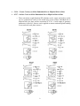
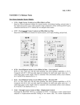
CC13 – Corner Crack at Edge Notch in Plate
SC26 – Surface Crack at Edge Notch in Plate
o These univariant weight function stress intensity factor (SIF) solutions are valid
for a corner and surface crack at the tip of an edge notch of arbitrary shape and
are extensions of TC17. Two common types of notch shape are supported in the
GUI (an angular straight-edge notch and an elliptical notch) for a very wide range
of geometry parameters. Stresses can be applied as remote tension/in-plane
bending or (un-cracked) crack plane stresses.
1
•
•
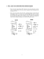
CC14 – Corner Crack(s) at Offset Embedded Slot or Elliptical Hole in Plate
SC27 – Surface Crack at Offset Embedded Slot or Elliptical Hole in Plate
o These univariant weight function SIF solutions are for corner and surface cracks
(or two symmetrical cracks) at the notch tip(s) of an (offset) embedded slot or
elliptical hole in a plate and are extensions of TC18. A wide range of geometry
parameters is allowed. Stresses can be applied as remote tension/in-plane bending
or (un-cracked) crack plane stresses.
2
•
•
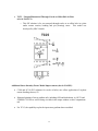
CC15 – Corner Crack at Offset Hole in Plate with Broken Ligament
SC28 – Surface Crack at Offset Hole in Plate with Broken Ligament
o These univariant weight function SIF solution are for corner and surface cracks at
a hole in a plate with one of the net sections completely broken through and are
extensions of TC19.
o These crack cases can be used to describe a continuing damage scenario after the
short ligament in the TC13 crack case is broken through and a corner or surface
crack initiates at the opposite side of the hole. The broken ligament is represented
by two parallel edge surfaces with an infinitesimal gap. Stresses can be applied as
remote tension/in-plane bending or (un-cracked) crack plane stresses.
3
•
TC23 – Unequal Diametrical Through-Cracks at Offset Hole in Plate
(also in NASCCS)
o This SIF solution is for two unequal through-cracks at an offset hole in a plate
under remote tension, bending and pin (bearing) stress. This model was
developed by NRC-Canada.
Additional Stress Intensity Factor Model Improvements (also in NASSIF):
•
CC08 and SC18 (WF solutions for cracks at holes) now allow application of in-plane
remote bending stresses, S2.
•
Enhanced printing of stress gradient info, including OPS and shakedown, in .OUT1 and
STRESS.CSV files as well as being viewable in the output window on the Computations
tab.
•
For TC15, the capability to plot the input stress gradient data was added.
4
Other New NASFLA Features:
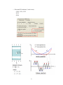
•
Implemented ability to compare graphs of two material IDs (user or NASGRO file) on
Material tab by clicking on the “Compare two IDs” button:
•
Implemented the Willenborg load interaction models for 3-D and 4-D cracks, including
the generalized Willenborg model, the modified Willenborg model, and ChangWillenborg model.
•
Implemented the capability to handle situations where the structural responses (stress
gradients) of a complex system at time instants t1 and t2 of a cyclic loading are different.
This new feature is available on the “Geometry” GUI screen for the following weight
function solutions:
o Univariant WF solutions (12 crack cases):
- TC11, TC12, TC13, TC17, TC18, TC19
- CC08, CC11
- SC17, SC18
- EC02, EC05
5
o Bivariant WF solutions (5 crack cases):
- CC09, CC10, CC12
- SC19
- EC04
6
•
New fields in GUI and input file are now available for the user to supply information
describing the problem being analyzed. This feature is accessible from the “Output
Options” GUI screen. See below.
•
Implemented the capability for computing the number of cycles to user-specified
intermediate cracks sizes. This feature is accessible from the “Output Options” GUI
screen:
•
User-defined limits for post-processing plotting of a second variable may now be entered.
•
Users may now add custom plot tiles to all plots/graphs.
•
For all plotting, the default plot axes limits will now be displayed on-screen prior to the
generation of the plot image. If there are numeric limits from the material database, those
will be shown. If the limits are based on computed data, asterisks will be shown.
•
Appended bracketed text to NASFLA GUI title bar indicating the current status of the
configuration control restrictions ("[no restrictions]" or "[configuration controlled]".
•
When both shakedown and limit stress checking are selected, the limit stresses will now
take into account the residual stresses from shakedown.
•
Provided output of the sorted iteration table in the NASFLA inverse calculations if the
iteration does not converge.
Additions (NASFLA & NASSIF):
•
Made the following modifications to OPS univariant stress data plotting:
o Added User Data to the OPS plot, as well as its Linear interpolation curve, for
comparison purposes with the OPS generated data points and the OPS generated
Hermite interpolation curve.
7
o Removed 'control knots' from the OPS plots. These are internal points used in the
data generation routines and by themselves are not relevant to the plot itself.
Additions (NASFLA, NASSIF, NASCCS, & NASGLS):
•
Upon completion of an analysis, the GUI will now automatically display the Output
Summary information in the display window on the Computations tab. Previously, the
user was required to manually click the View Output Summary button for this
information to be displayed.
•
Added a new "Release notes" button on the main NASGRO GUI opening screen and a
new individual GUI Help menu item "NASGRO release notes" which accesses the
distributed PDF file listing all features of the new NASGRO release.
•
For very short anaysis runs, it was possible for the newly saved input file timestamp to be
slightly older than its resulting out1file timestamp, causing a warning message to be
issued in error at the end of the run, when the output summary data is automatically
displayed in the output viewing window.
NASFLA Changes:
•
Included the net section stress caused by limit stress in net section yield (NSY) check for
weight function cases.
•
Excluded the applied peak stress from net section yield (NSY) check for weight function
cases.
•
For 3 and 4 DOF crack cases, the “Cth value used in analysis” option: “0 initially” is not
allowed.
•
Changed Willenborg text labels for Shutoff Overload ratio and Phi0, replacing term
“suggested” with “typical”.
•
When plotting material fits, separate independent access is now allowed for plotting
Basic fits, plotting Comparison fits, and showing the References data for each material
plotted via radio buttons on the Material GUI page.
•
On the Load Blocks tab, the default block type has been changed from predefined block
to manual input.
8
•
Crack case CC08, SC18, TC13: OPS option will be automatically selected whenever
“crack stress definition” is set to “remote tension” (CC08, SC18), or “tension,bend”
(TC13).
•
Internal routine to determine crack case 3- or 4-dimension status was corrected, and
appropriate GUI restrictions based on this status are now done correctly, such as
allowable load interaction models.
•
An internal storage array associated with a grid was not expanded to a newer, larger size,
which was needed when the associated grid itself was previously expanded. This resulted
in intermittent problems with the GUI.
•
Changed the mechanism to handle flat load steps for the load blocks entered by "Select
file(s) containing long block(s)": Before version 7.0, no check for flat load steps was
present. In version 7.0, a check was implemented such that if a flat load step is detected, a
warning will be printed, but the computation will continue.
•
When plotting a material Basic Fit, the on-screen value of Kc will now be shown with
one decimal place and also display the average thickness value on which it is based.
Changes (NASSIF):
•
Crack case TC13: Optimum point spacing will now always be used when selecting
"Tension,bend" for crack plane stress definition.
Changes (NASCCS):
•
Clarified the following field labels on the Output Options tab:
o "Critical SIF" changed to "Fracture toughness"
o "Critical stress" changed to "Yield (or flow) stress"
o Enclosed the above two fields and labels within a new box labeled: "Critical
material properties"
o Enclosed the actual stress entry controls ("S0","S1","S2","S3","S4") within new
boxes labeled "Applied stresses"
9
NASFLA, NASSIF Changes
•
When OPS is not enabled, the stress variations used to determine K values are assumed to
vary linearly among user-specified stress data pairs. Previously, the variations among
stress data pairs were always represented by Hermite polynomials regardless of OPS
being enabled or not.
NASFLA, NASSIF, NASCCS, NASGLS Changes
•
For crack cases CC04, CC07, and SC04, the crack case diagrams have been revised and
clarified.
•
Crack cases DT01, DT02, DT03:
- The default interpolation type for these data table solutions has been changed
from Spline to Linear.
- User dimension D, formerly blank, will now default to a value of “1”.
•
Removed crack case DT04.
•
Crack case SC13: Corrected the geometry check for solution inaccuracy for r/D outside
the range [0.005 .. 1.0]. This check, which was added in NASGRO version 6.12, did not
correctly handle all formats of the major diameter D, as displayed in the “Bolt major and
minor diameter” selection list.
•
Crack case SC04: Changed output text, clarifying it to distinguish the hoop-stress effect
of internal pressure from the cumulative effect of the hoop-stress and the direct crackopening effect.
•
Crack cases CC02, CC04, CC07: Refined solution limits and added dynamic bitmap
display based on number of flaws selected (CC02, CC07).
•
Updated various bitmaps for weight function crack cases to specifically show the
independent dimensional and non-dimensional coordinates, and additional expressions
for limits.
• When checking throughout a block for crack instability and net-section failure at limit
stress, the on-screen text of "limit stress for stress quantity" has been changed to "scale
factors for limit stresses" when crack plane stresses are specified.
10
NASFLA Fixes
•
The following corrections have been made to the materials files:
- Removed duplicate entries for Jethane M152 (ID: L6AB28AB1)
- Corrected the value of Bk for 7050-T7451 (IDs: M7GJ11AC1 & M7GJ12AC1)
- Corrected the value of n for 7475-T761 (ID: M7TI11AB1)
- Corrected the value of C for Inconel X-750 (ID: Q3SD26LA2)
•
The Computations tab "Save window contents to doc file" button would be permanently
disabled if the "Do parameter analysis" checkbox was checked.
•
Removed "Input:SIF Comp" as a selection on the Computation tab's "Select output to
view:" listbox whenever SIF Compounding was used in the analysis. This separate
out1file display choice interrupted the display of "Initial crack size" as part of the
"Input:Geometry" data display. Removing "Input: SIF Comp" allows both the SIF
compounding out1file data and the initial crack size out1file data to both be properly
displayed when "Input: Geometry" is selected.
•
Shakedown GUI controls (text label and entry grid) were not removed from the Material
tab when Shakedown option was set to "None".
•
Crack case SC19: corrected typo in geometry error for a/c upper limit. While the GUI
correctly disallowed ratios greater than 8.0, the warning message erroneously stated "0.8"
as the upper limit.
•
Crack case BE02: Corrected tip designation for Material tab's "Kc value at tips" fields
from "a-tip" and "c-tip", to "c-tip" and "c1-tip".
•
Crack cases SC17, SC18, TC11: Material tab fields "Kc values at tips", which previously
always showed the number of tips for the non-symmetric states, will now be updated to
also show the correct number of tips for the symmetric states.
•
Major overhaul of the monotonic and cyclic shakedown algorithms was required due to
incorrect performance of shakedown feature.
•
Crack case SC17: an inconsistent designation for bending during remote tension/bending
or polynomial stressing led to too small a value for "Lr” for FAD option 1. This has been
corrected.
11
•
Crack case EC05: An incomplete calculation for crack tips' computed Kr values caused
an improper program exit during an analysis, resulting in termination and a non-specific
error message.
•
Crack case TC11: Incorrect failure criteria code used in computation for symmetric
cracks caused computations to fail immediately. This has been corrected.
•
Corrected the legend entry when viewing output plot data for beta factor F1(a), which
erroneously read “F0(a)”.
•
Crack case SC18: the residual stress checkbox was not being redisplayed when
shakedown option was turned off.
•
Crack case TC15: corrected internal condition preventing some analyses from running.
•
For analyses using the Strip Yield load interaction model, the value for the "fast run"
output option "% difference for Sopen values to be deemed stable:" was not being written
to the batchfile properly, preventing the run.
•
Corrected a memory error with Optimum Point Spacing for cyclic shakedown.
•
Crack case CC14: Enabled the Strip Yield load interaction model to work properly with
this crack case.
•
Crack case SC28: an error in writing crack size data to batchfile caused incorrect results.
•
Several individual material parameter fields were shown on the Material tab
inadvertently, as a result of loading a NASFLA input file for which no material data had
been saved.
•
NASFLA GUI would crash during the selection of a temperature-related material ID, if
the Cancel button was clicked during the selection of the form/orientation/environment
set to be used in calculations.
•
When using predefined block data on the Load Blocks tab, the data displayeed in the grid
was not being properly updated for BLOCKS or BLOCKT databases when a material ID
selection was changed between a temperature-related material ID and a non-temperaturerelated material ID.
•
Basic and Comparison curvefits and References for temperature-based materials could
not be plotted or viewed.
•
If more than four temperature-dependent load blocks were used in an analysis, varying
output results occurred.
12
•
Crack case CC09: crash of computational core occurred due to incorrect memory usage.
•
A batchfile error prevented analyses from running in elastic-plastic mode.
•
Some R-values on material curvefit plots were incorrectly represented in exponential
notation.
•
Incorrect value shown in the plot legend REF column when plotting the Basic fit for
material ID M7GJ11AB01 for data ID M7GJ11AB01J1.
•
Crack case SC27: an error in writing crack size data to batchfile caused incorrect results.
•
The following GUI radioboxes were not prompting the user to resave input when their
settings were changed: "Cth value used in analysis", "Temperature interpolation type",
"Strip yield computational speed choice", "Select Willenborg Model", "Closure factor
CFspec computed from", "Through crack toughness computed from".
•
Properly relabeled the View Output button on the Computations tab after an analysis has
been re-run with changed input to read "Show selected details" if any detail selections
were made prior to the re-run.
•
Corrected inadvertent data written to batchfile that prevented some analyses from
running.
•
When plotting material comparison fits, the "Quit" button did not end the plot
functionality as intended, and all subsequent material comparison plots would still be
prompted for viewing.
•
Fixed a bug in SC05-TC08 transition to convert crack size (c) due to different definitions
of the crack size in the two crack cases.
•
Corrected a problem with commentary lines in the out2 file which caused the GUI to
crash when selecting all details to show after calculations have completed.
•
The button "Compare two IDs" was being incorrectly shown on the Material tab for
Elastic-Plastic mode. This functionality applies only to "Linear-Elastic" mode.
•
The error "Some material parameters not defined, cannot plot." would be shown when
loading an input file that did not contain any material data.
•
Post-processing plot of Residual Strength by NSY was incomplete for some analyses
containing crack transitions.
13
•
An error in the spectrum editing functions caused an incorrect number of cycles to be
written to the last line of the edited file, which would either add or subtract cycles to the
last step of the edited spectrum.
•
For ID Q3LP18AB1, the ultimate tensile strength was corrected to 205 ksi, after
verification.
•
Stability issue when involving temperature dependent material properties specified in
USRMTM. The problem manifested itself by not generating any fatigue crack growth
prediction for the specified interpolated temperature and at the applied stress level larger
than and close to the threshold stress. This release should resolve this problem that
allows users to apply stress level very close to the threshold stress.
•
The threshold values at c-tip in the OUT2 file were all marked by 'x' instead of showing
their numerical values. It was found this bug was related to the above stability bug fix
where temperature effect was accounted for as a result of incorrectly-computed threshold.
•
Crack case SC17: For symmetric crack input (W=B/2), the geometry edit on the Crack
Size Limits fields was incorrect. For a symmetric crack, only the 'a' and 'c' limits fields
are shown, while the geometry edit logic was referencing the 'c' and 'c1' limits fields,
requiring equal entries. This check has been removed.
•
User may receive an array overflow error message when selecting a second ID in the
"Compare Two IDs" dialog.
•
Incorrectly converted values for entered R-values prevented the plotting of tabular
material data.
•
When saving plotted tabular material data to text file, a GUI crash occurred, preventing
the saved log values in the file from being converted to anti-log values.
•
Crack case SC18 output showed inconsistent a, c and a/c values as well as NaN (not a
number) printed at the final result summary section for DKth and DK. Two errors were
identified and resolved. One was from the SC18 fracture mechanics software module,
which could affect the computed reference solution through dynamic K table
interpolation when NASFLA GUI was utilized. The other resulted from incorrect output
designation such that inconsistent values were printed.
NASSIF Fixes
•
Crack case CC11: The upper validity limit for crack shape aspect ratio a/c was incorrectly
implemented. The fix implemented the correct upper bound ratio; i.e., a/c=40.
14
•
An internal variable became un-uninitialized, causing program crash.
•
A memory leak caused by allocated memory which was not correctly de-allocated has
been corrected.
•
Some uninitialized variables used in batch mode for multiple input files caused incorrect
results. This has been corrected.
•
An un-initialized variable resulted in unnecessary memory allocation, leading to an
“unable to allocate” message when running multiple input files in batch mode. This has
been corrected.
•
Crack case SC17: internal sub-program names were isolated and renamed, to resolve a
problem of slightly different results due to possible reuse, when running multiple input
files.
•
Crack case SC04: An invalid program structure resulted in a “NaN” (not a number) error.
•
Crack case SC04: An uninitialized variable resulted in an inconsistent echo of userprovided stress values in the output.
•
Crack case TC18: uninitialized variables in internal static libraries caused different output
results.
•
Crack case TC11: An extraneous character written to the output of the SIF table has been
corrected/removed.
•
Crack case EC04: Unnecessary memory allocation during computations in batch mode
caused early termination due to “unable to allocate” memory error. This has been
corrected.
•
Crack case CC09: error in OPS routines has been corrected.
•
Crack case CC10: Corrected the problem of “INF” (meaning: “infinite”) value written to
the output, due to an incorrect computed crack depth ratio.
•
Crack case CC12: Incorrect program calls to crack transition routines caused program
crash.
•
Crack case CC11: Corrected inconsistent results output due to internal library issues.
15
•
Crack case CC08: An uninitialized variable caused the following error to be erroneously
issued: “Crack size exceeds bounds for solution accuracy.”
•
A memory leak caused by internal library was identified and corrected.
•
Crack case TC17: Very small point spacing caused accumulation of numerical
inaccuracies. Improvement in the pre-integration routine has corrected this issue.
•
Crack case TC15: A problem with the index searching algorithm caused inconsistent SIF
results with crack case TC12. This has been fixed.
•
Crack case TC18: Very small point spacing at the notch tip, causing a large number of
points during iteration, resulted in an extremely long analysis completion time. Revisions
to the OPS routines have corrected this issue.
•
Crack case SC10: corrected an error that was preventing the applied stress (S0) from
being echoed in the output file when computing SIF values.
•
Crack Case TC11: Several uninitialized variables caused differing results between batch
mode processing and single input file run mode for the same set of input values. This has
been corrected.
•
Crack case TC13: "Include residual stress" checkbox inadvertently remained on-screen
when stress distrubution selection set to "Tension, bend".
NASFLA, NASSIF Fixes
•
Crack case SC17: The interpolation scheme among reference K solutions has been
revised due to a strange SIF variation near a/c=1 for a fixed surface crack length.
•
Crack case SC18: the interpolation scheme among reference K solutions has been revised
due to a strange SIF variation for crack shape aspect ratio around 1.0.
•
Crack case SC19: The interpolation scheme among reference K solutions has been
revised due to a strange SIF variation for a/c near 1.0 for a fix crack depth.
•
Crack case CC08: The interpolation scheme among reference K solutions has been
revised due to a strange SIF variation for a/c near 1.0 for a constant surface crack length.
16
•
Crack case CC10: The interpolation scheme among reference K solutions has been
revised due to a strange SIF variation for a/c near 1.0 for a constant surface crack length.
•
Crack case TC17: when changing the notch shape, the geometry grid entries common to
both configurations, if entered, will be retained.
•
Crack case TC18: when changing the embedded hole shape, rows in the geometry grid
labeled “Hole half-width, d”, “Notch tip radios, r” (for straight-edge hole) and “Semimajor axis, e1”, “Semi-minor axis, e2” (for elliptical hole) will no longer be retained,
since these values are unique to only one embedded hole shape.
•
When using separate tension/compression data via files, plotting this data could result in
a “file missing” error due to an incorrect internal filename reference.
•
Crack case TC18: solution validity limits have been corrected, both in the displayed crack
case diagram and the geometry edit checking routine; straight-edge slot upper limit of
(d+r)/B corrected from 0.9 to 0.75; elliptical hole: upper limit of e1/B corrected from 0.9
to 0.75.
•
Crack case TC18: solution validity limits have been corrected, both in the displayed crack
case diagram and the geometry edit checking routine; expression: “0 <= B/W <= 0.75”
corrected to: “0 <= (B+D/2)/W < 0.75”.
•
Crack case TC13: When the input values for crack dimension are exactly at the limits for
solution accuracy/validity, a computation core error was issued. An additional tolerance
has been implemented to allow for such a numerical accuracy problem.
•
A screen layout issue caused GUI input grids that needed exactly one scrollbar (either a
vertical or horizontal) to also have a second unneeded one. (Also in NASCCS &
NASGLS.)
•
Validation of maximum allowed value for crack size 'c' was incorrect, preventing certain
inputs from running.
•
Corrected a problem with Optimum Point Spacing for residual stress.
•
Crack case CC14: corrected a typo in the routine that checks the solution validity limits
for the elliptical hole configuration, which prevented some analyses from running.
17
•
2D (bivariant) stress input files were not being read/converted properly during plotting
("Plot Stresses" button), preventing stress plotting and incorrectly displaying the error
message "Number of points in x-direction must be an integer."
•
Corrected an "Nan" error that resulted from incorrect temperature interpolation.
•
The option to save plots in PNG format was inadvertently lost.
•
When saving plotfile data to external file, the chosen file extension was not added to the
filename, if that filename contained a period.
•
Crack case TC11: computational core assumed the incorrect symmetry option for nonsymmetric loading during calculations.
•
Crack cases CC14, SC27: incorrect data written to batchfile prevented some analyses
from running.
•
Corrected error causing incomplete computations related to Optimum Point Spacing.
• Removed inadvertent characters shown in the out2 file when stress gradients at common
point spacing are displayed.
•
While running NASSIF, the number of data pairs under the "USER-DEFINED stress
gradients" label in the OUT1 was inconsistent with the number of data pairs in the input
deck. The scenario occurred only when the user-defined stress gradients contained two
stress data pairs.
•
Crack case CC02: \"Plot table data\" buttons for 2D SIF Compounding were not removed
from screen when changing from 1D SIF Compounding to 2D SIF Compounding.
•
The column output for step number contained in the OUT2 file had an "x" instead of
showing its numerical step-wise values.
•
SIF Compounding controls were inadvertently turned on in the GUI when a geometry
grid entry was edited, causing an invalid batchfile format which prevented the analysis
from running.
Fixes (NASFLA, NASSIF & NASCCS):
•
For crack case CC07 (one crack solution):
o Corrected a data error in the fundamental geometry factor table for pin load,
changing the data value from 6.0 to 0.5512.
18
o Corrected a coding error in the calculation of geometry factor (F3) under pin load.
•
Crack Case SC05: Changed geometry check, expressing it in terms of D/t instead of
t/Dmean. The accuracy-limiting bound on D/t was changed to 4.0 exactly.
•
For crack cases CC02, CC04, and CC07 the following ranges of applicability were
verified and are now displayed in the GUI:
o CC02, CC04, and CC07 two crack solution:
0.2 ≤ a/c ≤ 2.0
1.0 ≤ D/t ≤ 4.0
(D/2+c)/B < 0.5
o CC07 one crack solution without bending:
0.1 ≤ a/c ≤ 2.0
0.5 ≤ D/t ≤ 4.0
o CC07 one crack solution with bending:
0.2 ≤ a/c ≤ 2.0
1.0 ≤ D/t ≤ 4.0
(D/2+c)/B < 0.5
•
Corrected a problem that occurred during batch mode processing where a single input file
containing bad data would stop the entire batch process. (b.1371)
•
Crack case SC07: the zone of validity was changed to a < 0.5 D, making it correspond to
the domain for which numerical results are available in the source document for this
solution. (b.1406)
Fixes (NASGLS):
•
Crack cases CC08, TC13: For the crack plane stress definition selection of
"Tension,bend", corrected the Load Blocks tab stress quantities displayed to properly
show S0 and S2 (instead of only S0).
•
Crack case CC08: The addition of bending stress S2 and subsequent rewriting of the
batch file creation routines in version 7.00 alpha introduced problems which prevented
analyses from running.
19
NASCCS Fixes
•
Changing the value in “Critical SIF” text field did not prompt to re-save the input file.
•
Crack cases CC08, SC18, TC13: For the crack plane stress definition selection of
"Tension,bend", corrected the Output Options tab: Applied Stresses labels to properly
show S0, S2 (instead of S0, S1).
•
Crack cases CC08, SC18: The addition of bending stress S2 and subsequent rewriting of
the batch file creation routines in version 7.00 alpha introduced problems which
prevented analyses from running.
•
Crack cases CC08, SC18: Corrected a batch file error that prevented older (pre-7.00
alpha) input files from running, if the stress distribution selected was "Remote tension".
NASMAT Fixes
•
Made corrections to fix the following errors noted when using the Spline option to
perform a Curve Fit and Plot:
- Fit lines were being displayed for all but one of the data sets being curve fit.
- The Add/Sort option in the Values from spline fit window displayed erroneous
values of DeltaK for user-entered values of da/dN. This feature is presently
disabled.
- The Print Table option in the Values from spline fit window did not function, and
instead triggered an error message.
- The Print Report option in the Values from spline fit window did not function,
and instead triggered an error message.
•
Corrected a formatting error with M2IF12AB01E1. M2IF12AB01E1 now properly
displays data.
•
Adding a da/dN value to Spline fit was disabled.
•
Spline fit altered to correctly graph all R-values.
•
Fixed the 'Save Changes' button on the Examine/Edit dialogue to prevent occasional
crash to desktop.
•
Fixed crash from placing the NASMAT data files in a long file path.
20
•
Corrected "write all data" behavior in Examine/Edit pane to prevent writing of extraneous
data values at end of file when switching between multiple material IDs.
•
Corrected issues with the User and NASA toughness check boxes on the Toughness
Notes page. Checkboxes may only search one file at a time, and only display "Edit/Enter"
data when the user has permission to edit that file.
•
On the Toughness Notes page, some searches were listing entries, but not displaying
them when "Show Selected Data" or "Enter/Edit Data" were chosen. This has been
corrected to properly show all data that matches the filter criteria.
•
On the Toughness notes pages, selecting some specimen types were displaying a different
number of matches than shown when viewing the matches on the "Enter/Edit" or "Show
Selected Data" page. This has been corrected, and the number of specimen types that can
be used to filter the results expanded.
•
Pressing the "Enter/Edit Data" button on the Toughness Notes page would bring up a
superfluous pop-up stating "Please Enter a data ID". The pop-up has been removed.
•
The Toughness Notes page was unable to open the user toughness data file. This has been
corrected.
•
The Toughness Notes pages would display erroneous numbers when selecting a filter
criteria when no ID had been selected. This has been changed to properly display "0".
•
NASMAT's utilization of the Windows Registry to store some user specific data has been
changed to use an initialization file instead. NASMAT no longer utilizes the Registry.
•
Removed NASMAT's reliance on shared memory when executing nasmat.dll, and
replaced it with a file pipe. This change simplifies the coding required for future changes,
as well as fixes occasional issues caused by the shared memory not creating properly.
•
Fixed an issue where modifying selection criteria on the Toughness Notes pages would
not modify the displayed data to match the modified criteria, or would not display data at
all.
•
Resolved multiple issues where NASMAT would not properly plot material ID's when
using the "New Curvefit/Plot" button with only plot checkboxes selected. (b.1373,1383,
1400)
•
For ID: Q3LP18AB1, the ultimate tensile strength was corrected to 205 ksi, and the yield
strength was changed to 180 ksi, after verification. (b.1378)
21
•
Resolved issues when saving or editing data in the user or NASA data files. When editing
or adding data, material ID entries would occasional duplicate, or be saved without
capturing all of the changes. (b.1375, 1382)
•
Resolved issue where NASMAT would occasionally throw an error message when
viewing da/dN points on the Enter/Examine Edit dialog. (b.1399)
•
Fixed issue that caused plots to fail on occasion due to extraneous white spaces in the
data file. (b 1389)
•
Crack growth data for the following materials were added to the files and made available
to the user:
ID: M2EA11AB01F & M2EA11AB01L: 2024-T3
Recent Changes Documentation
•
All “Recent Changes” lists have been reformatted, separating them by NASGRO release
version.
•
Multi-level selection menus have been added for easy access to the individual lists for
each previous NASGRO release.
•
In addition, a new, single overall list containing the changes for all previous NASGRO
releases as well as the current release has been created.
Fixes (Configuration Control):
•
If any non-default values were entered for the fields for the fields “a0”, “Kth ratio”, or
“Cth option”, the “Remove all restrictions” button would not reset these fields to their
default values. At that point, a standard, “no restrictions” NASFLA configuration control
file could not be created unless the Configuration Control GUI was closed then restarted.
Fixes (Manual):
•
Corrected link in User Manual Table of Contents for Appendix U, which was incorrectly
linked to Appendix V.
22
Linking Excel to NASFLA:
NASGRO v6.2 was released with several Excel files, each of which contained a worksheet
customized to accept input for a particular NASGRO crack case: TC01, TC03, TC05, and SC01.
For NASGRO v7.0, these worksheets have been combined into a single Excel file located in the
"nasfla\excel_templates" subfolder of the data files installation location. For example, if the
NASGRO data files are installed in "C:\Documents and Settings\username\My
Documents\nasgro7.0\", then the Excel file would be installed in "C:\Documents and
Settings\username\My Documents\nasgro7.0\nasfla\excel_templates". In addition, for safekeeping, the data files installation procedure puts a copy of this file in the "Archived originals do not delete" subfolder to "excel_templates".
In addition, upon opening the worksheet, the cell containing the location of where all generated
input and output files will be saved is now pre-filled with the Excel file's location. As in
previous versions, this can be changed by the user or left blank (in which case the location
defaults to the user's desktop).
23