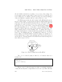
1
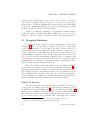
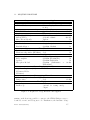
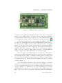
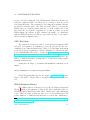
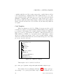
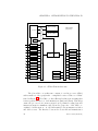
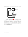
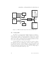
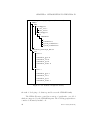
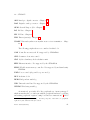
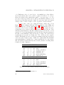
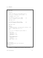
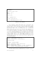
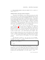
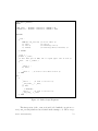
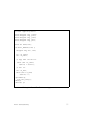
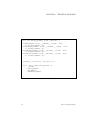
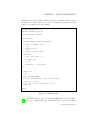
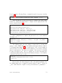
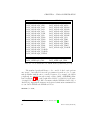
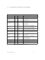
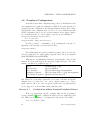
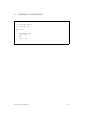
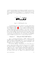
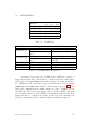
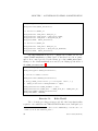
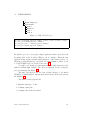
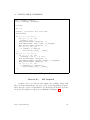
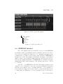
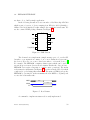
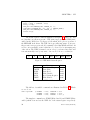
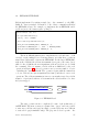
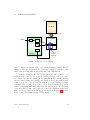
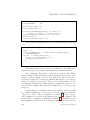
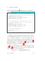
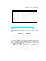
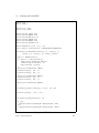
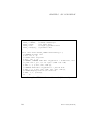
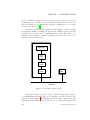
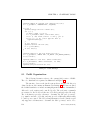
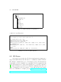
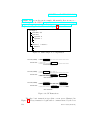
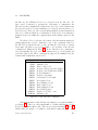
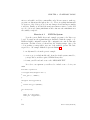
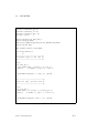
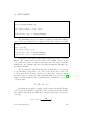
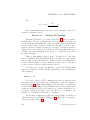
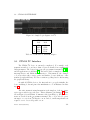
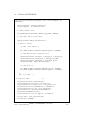
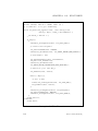
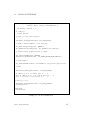
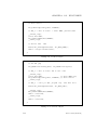
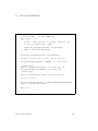
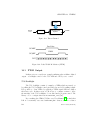
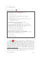
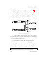
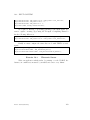
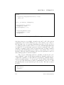
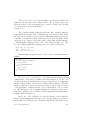
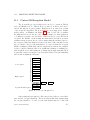
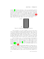
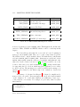
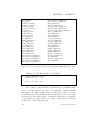
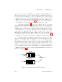
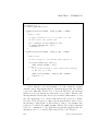
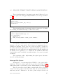
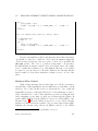
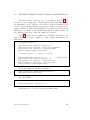
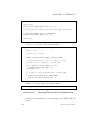
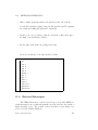
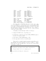
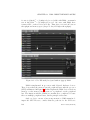
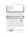
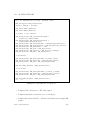
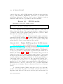
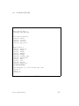
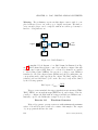
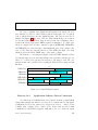
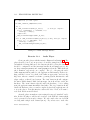
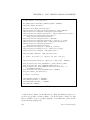
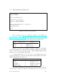
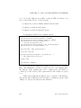
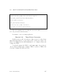
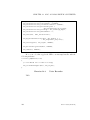
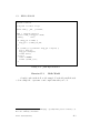
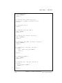
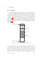
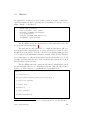
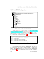
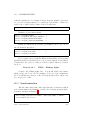
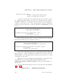
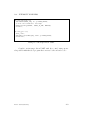
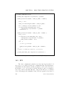
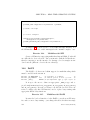
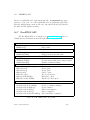
8.2. SD DRIVER
(in this case the STM32) followed by a response from the SD card. For
pure control operations (e.g querying the card status or configuration, the
SD card response terminates the transactions. For read or write transactions,
the response is followed by the transmission of a data block from (write) or to
the host (read). There are other cases including multi-block data transactions
and error conditions which are not illustrated. It should be clear that these
transaction types are sufficient to implement the functionality required by the
FatFs.
We will not delve deeply into the format of the information transferred
during transactions except to enumerate a few of the commands defined by
the SD Card specifications and to point out that all of the fields of a transaction may optionally be protected by CRC codes. A subset of the SD card
commands are illustrated in Table 8.2. Notice that there are commands to
reset and initialize the card, read/write parameters (e.g. block length), and
read/write data blocks. These commands are supported by multiple response
formats with lengths that vary from 1-5.
Command
CMD0
CMD1
CMD8
CMD9
CMD10
CMD12
CMD13
CMD16
CMD17
CMD18
CMD24
CMD25
CMD58
ACMD23
ACMD41
Description
Reset the SD Card
Initialize card
Write voltage level
Request card-specific data (CSD)
Request card identification (CID)
Stop transmission
Request card status
Set transfer block length
Read single block
Read multiple blocks
Write single block
Write multiple blocks
Read OCR register
Number of blocks to erase
Initialize card
Table 8.1: Some SD Card Commands
Our implementation of the SD driver is a simple port of generic/mmbc.c
(see Figure 8.3). There are only a small number of routines that must be modified in order to utilize this module. These are presented in Listings 8.3 and 8.4.
Additionally, the sample code utilizes a wait function (DLY_US) that counts
Revision: 1396a85 (2013-01-07)
117