1
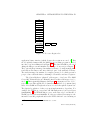
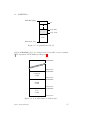
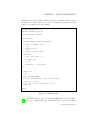
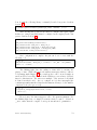
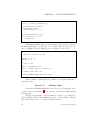
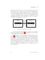
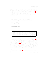
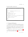
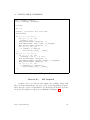
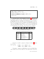
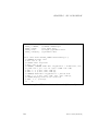
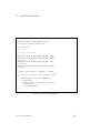
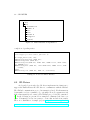
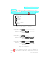
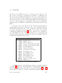
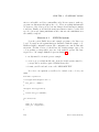
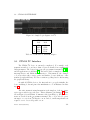
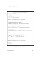
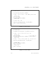
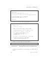
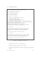
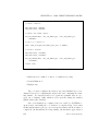
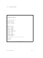
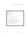
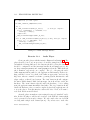
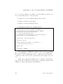
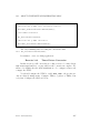
4.3. ALTERNATIVE FUNCTIONS
volatile uint32_t
volatile uint32_t
volatile uint32_t
volatile uint32_t
volatile uint32_t
volatile uint32_t
volatile uint32_t
} GPIO_TypeDef ;
CRL;
CRH;
IDR;
ODR;
BSRR;
BRR;
LCKR;
The 16 bits of each port are configured with CRL (bits 0-7) and CHR (pins
8-15). To support the various I/O modes, 4 configuration bits are required for
each GPIO bit. The 16 GPIO bits can be read in parallel (IDR) and written in
parallel (ODR). As a convenience, registers BSRR and BRR provide a mechanism
to set and reset individual bits. The lock register LCKR provides a mechanism
to “lock” the configuration of individual bits against software reconfiguration
and hence protect hardware from software bugs.
Exercise 4.2
Blinking Lights with Pushbutton
Modify the blinking lights program to additionally track the state of
the user pushbutton (PA0) on the blue LED (PC8). See if you can figure out
how to configure both LEDs with a single call to GPIO_Init.
4.3 Alternative Functions
Peripherals such as the USARTs share pins with the GPIO devices.
Before these peripherals can be utilized, any outputs required by the peripheral
must be configured to an “alternative mode”. For example, the Tx pin (data
out) for USART1 is configured as follows:
GPIO_InitStruct . GPIO_PIN = GPIO_Pin_9 ;
GPIO_InitStruct . GPIO_Speed = GPIO_Speed_50MHz ;
GPIO_InitStruct . GPIO_Mode = GPIO_Mode_AF_PP ;
GPIO_Init (GPIOA , & GPIO_InitStruct );
The specific configuration required for each peripheral is described in
section 7.1.11 of the stm32f10xx reference manual RM0041 [20] (section 9.1.11
for stm32f103xx reference manual RM0008 [21]).
4.4 Remapping
It is also possible to “remap” pins so that non-default pins are used for
various peripherals in order to minimize conflicts. These re-mappings, which
Revision: 1396a85 (2013-01-07)
65