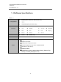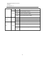
1
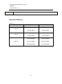
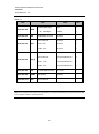
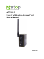
AW5500C Industrial Wireless Access Point User’s Manual v.1.0 February 2014 Atop Industrial Wireless Access Point AW5500C User Manual V. 1.0 Important Announcement The information contained in this document is the property of Atop Technologies, Inc., and is supplied for the sole purpose of operation and maintenance of Atop Technologies, Inc. products. No part of this publication is to be used for any other purposes, and it is not to be reproduced, copied, disclosed, transmitted, stored in a retrieval system, or translated into any human or computer language, in any form, by any means, in whole or in part, without the prior explicit written consent of Atop Technologies, Inc., offenders will be liable for damages. All rights, including rights created by patent grant or registration of a utility model or design, are reserved. Disclaimer We have checked the contents of this manual for agreement with the hardware and software described. Since deviations cannot be precluded entirely, we cannot guarantee full agreement. However, the data in this manual is reviewed regularly and any necessary corrections included in subsequent editions. Suggestions for improvement are welcome. All other product names referenced herein are registered trademarks of their respective companies. Published by Atop Technologies, Inc. 2F, No. 146, Sec. 1, Tung-Hsing Rd. Jubei, Hsinchu 30261 Taiwan, R.O.C. Tel: 886-3-5508137 Fax: 886-3-5508131 www.atop.com.tw www.atop-tech.com Copyright © 2014 Atop Technologies, Inc. All rights reserved. Technical data is subject to change. All other product names referenced herein are registered trademarks of their own respective companies. ii Atop Industrial Wireless Access Point AW5500C User Manual V. 1.0 Contents 1 Preface ..................................................................................................... 1 2 Introduction.............................................................................................. 5 3 4 2.1 Product Overview ......................................................................................................5 2.2 Features .....................................................................................................................6 Getting Started......................................................................................... 7 3.1 Inside the Package ....................................................................................................7 3.2 Front & Power Panels ...............................................................................................8 3.3 First Time Installation ............................................................................................ 10 3.4 Finding the Device .................................................................................................. 11 3.5 Factory Default Settings ........................................................................................ 13 Web Console Configuration ................................................................. 17 4.1 Overview Information ............................................................................................ 17 4.2 User Interface Overview ........................................................................................ 17 4.3 Secure Wireless Network ...................................................................................... 19 4.4 Wireless Settings ................................................................................................... 19 4.4.1 Wizard ............................................................................................................ 20 4.4.2 Basic Settings ................................................................................................ 20 4.4.3 Security Settings ............................................................................................ 28 4.4.4 WPS Settings ................................................................................................. 34 4.4.5 WDS Settings ................................................................................................. 35 4.4.6 Advanced Settings ......................................................................................... 36 4.4.7 Wireless Scheduler Settings .......................................................................... 38 4.5 Network Settings .................................................................................................... 41 4.6 SNMP Settings ........................................................................................................ 42 4.7 Email Settings......................................................................................................... 44 4.8 DHCP Server ........................................................................................................... 45 4.9 Firewall & Filtering ................................................................................................. 47 4.9.1 Wired MAC Filtering ....................................................................................... 48 4.9.2 Wireless MAC Filtering .................................................................................. 49 4.9.3 Ethernet Type Filtering................................................................................... 50 4.9.4 IP Filtering ...................................................................................................... 51 iii Atop Industrial Wireless Access Point AW5500C User Manual V. 1.0 4.9.5 Management List ........................................................................................... 52 4.10 System Log ............................................................................................................. 53 4.10.1 Syslog ............................................................................................................ 53 4.10.2 Event Log ....................................................................................................... 54 4.11 System Setup.......................................................................................................... 55 4.11.1 Admin Settings ............................................................................................... 55 4.11.2 Date/Time Settings ........................................................................................ 56 4.11.3 Alert Event ..................................................................................................... 57 4.11.4 Firmware Upgrade ......................................................................................... 58 4.11.5 Backup & Restore Configuration ................................................................... 59 4.12 System Status......................................................................................................... 60 4.12.1 System Information ........................................................................................ 60 4.12.2 Site Monitor .................................................................................................... 61 4.12.3 Wireless Client Table ..................................................................................... 63 4.12.4 Traffic Log & Statistics ................................................................................... 64 4.12.5 DHCP Status .................................................................................................. 65 4.12.6 Ping ................................................................................................................ 66 4.13 Reboot and Restore Default Settings .................................................................. 67 5 6 7 Operation Modes ................................................................................... 68 5.1 Regular AP Mode .................................................................................................... 68 5.2 WDS Bridge Mode .................................................................................................. 71 5.3 AP Client Mode ....................................................................................................... 75 Applications ........................................................................................... 77 6.1 Basic Access Point Setup ..................................................................................... 77 6.2 Basic WDS Setup ................................................................................................... 78 6.3 Coverage Range Extender Setup ......................................................................... 79 6.4 AP Client Setup ...................................................................................................... 80 6.5 P2P Button (External Physical WPS button) ....................................................... 81 Specifications ........................................................................................ 84 7.1 Hardware Specifications ....................................................................................... 84 7.2 Software Specifications ......................................................................................... 94 7.3 LED Indicators ........................................................................................................ 95 iv Atop Industrial Wireless Access Point AW5500C User Manual V. 1.0 8 Emergency System Recovery .............................................................. 97 9 Warranty ................................................................................................. 99 v Atop Industrial Wireless Access Point AW5500C User Manual V. 1.0 1 Preface Purpose of the Manual This manual supports you during the installation and configuring of the AW5500C Industrial Wireless Access Point only, as well as it explains some technical options available with the mentioned product. As such, it contains some advanced network management knowledge, instructions, examples, guidelines and general theories designed to help users manage this device and its corresponding software; a background in general theory is a must when reading it. Please refer to the Glossary for technical terms and abbreviations (if any). Who Should Use This User Manual This manual is to be used by qualified network personnel or support technicians who are familiar with network operations; it might be useful for system programmers or network planners as well. This manual also provides helpful and handy information for first time users. For any related problems please contact your local distributor, should they be unable to assist you, please redirect your inquiries via www.atop.com.tw or www.atop-tech.com. Supported Platform This manual is designed for the AW5500C Industrial Wireless Access Point and that model only. Warranty Period We provide a 5 year limited warranty for AW5500C Industrial Wireless Access Point. 1 Atop Industrial Wireless Access Point AW5500C User Manual V. 1.0 Manufacturers Federal Communication Commission Declaration of Conformity Statement Model: AW5500C NOTE: This equipment has been tested and found to comply with the limits for a Class A digital device, pursuant to Part 15 of the FCC Rules. These limits are designed to provide reasonable protection against harmful interference when the equipment is operated in a commercial environment. This equipment generates, uses, and can radiate radio frequency energy and, if not installed and harmful interference used to in accordance with radio communications. the instruction Operation of manual, this may cause equipment in a residential area is likely to cause harmful interference in which case the user will be required to correct the interference at his own expense. This device complies with Part 15 of the FCC Rules. Operation is two conditions: (1) this device may not cause accept any interference subject to the following harmful interference, and (2) this device must received, including interference that may cause undesired operation. This device and its antenna(s) must not be co-located or operating in conjunction with any other antenna or transmitter. FCC Caution: Any changes or modifications not expressly approved by the party responsible for compliance could void the user's authority to operate this equipment. For product available in the USA/Canada market, only channel 1~11 can be operated. Selection of other channels is not possible. FCC Radiation Exposure Statement This equipment complies with FCC radiation exposure limits set forth for an uncontrolled environment. This equipment should be installed and operated with a minimum distance of 20 cm between the radiator & your body. 2 Atop Industrial Wireless Access Point AW5500C User Manual V. 1.0 European Community, Switzerland, Norway, Iceland, and Liechtenstein Model: AW5500C Declaration of Conformity with regard to the R&TTE Directive 1999/5/EC This equipment is in compliance with the essential requirements and other relevant provisions of 1999/5/EC. The following standards were applied: EMC EN 301.489-1 v1.4.1; EN 301.489-17 v1.2.1 Health & Safety EN60950-1: 2001; EN 50385: 2002 Radio EN 300 328 v 1.7.1; EN 301.893 v 1.5.1 The conformity assessment procedure referred to in Article 10.4 and Annex III of Directive 1999/5/EC has been followed. This device also conforms to the EMC requirements of the Medical Devices Directive 93/42/EEC. Note: This equipment is intended to be used in all EU and EFTA countries. Outdoor use may be restricted to certain frequencies and/or may require a license for operation. For more details, contact Atop Technical Support. European Union This system has been evaluated for RF exposure for humans in reference to the ICNIRP (International Commission on Non-Ionizing Radiation Protection) limits. The evaluation was based on the EN 50385 Product Standard to Demonstrate Compliance of Radio Base stations and Fixed Terminals for Wireless Telecommunications Systems with basic restrictions or reference levels related to Human Exposure to Radio Frequency Electromagnetic Fields from 300 MHz to 40 GHz. The minimum separation distance from the antenna to a general bystander is 20 cm (7.9 inches). UL Notice for Power supplier The AW5500C series products are intended to be supplied by a Listed Power Unit marked with a “LPS” (Limited Power Source), or “Class 2” and output rate of 9~48 VDC, 1.0 A minimum, or use the recommended power supply listed in “Optional Accessories”. 3 Atop Industrial Wireless Access Point AW5500C User Manual V. 1.0 Caution Beginning from here there will be extreme caution exercised. Never install or work on electrical cabling during periods of lightning activity. Never connect or disconnect power when hazardous gases are present WARNING: Disconnect the power and allow to cool 5 minutes before touching. 4 Atop Industrial Wireless Access Point AW5500C User Manual V. 1.0 2 Introduction 2.1 Product Overview The AW5500C Wireless Access Point series is our new line of wireless products designed to provide a wireless connectivity to clients or mobile stations creating a complete solution for your industrial wireless networking. As an example, you can connect serial devices to our Wireless Serial Device Server and connect these two to a Wireless Access Point device; this example illustrates how to connect serial devices to a local area network or a backbone network, Figure 2.1.The AW5500C series provide several functionalities to support mobile and wireless networking. Figure 2.1 5 Atop Industrial Wireless Access Point AW5500C User Manual V. 1.0 2.2 Features AW5500C is our latest addition to our Industrial Wireless products; its small size but powerful architecture makes it a perfect choice for industrial/manufacturing needs in which size is a decisive factor. It rewards our customers with superb connectivity. Among its many characteristics, we could mention: Stream input/output with maximum link speed of 300 Mbps and throughput of 100 Mbps (environment dependent). Wireless Isolation to enhance security between wireless clients. Different modes of operation: Regular AP WDS Bridge AP Client 6 Atop Industrial Wireless Access Point AW5500C User Manual V. 1.0 3 Getting Started 3.1 Inside the Package Inside the product purchased you will find the following items: Table 3.1 Item Quantity Description AW5500C 1 Industrial Wireless Access Point Antenna 1 3~5 dBi antenna Terminal Block 1 3-pin lockable terminal block Mounting Kit 1 DIN-Rail kit, already mounted on the device’s back plate Inside the CD you will find: Documentation + CD (Utilities) 1 User’s Manual Installation Guide Device View © Utility Note: Please notify your sales representative if any of the above items is missing or damaged in any form upon delivery. If your sales representative is unable to satisfy your enquiries, please contact us directly. 7 Atop Industrial Wireless Access Point AW5500C User Manual V. 1.0 3.2 Front & Power Panels The Front (Figure 3.1), and Power panels (Figure 3.2), are as follow: Figure 3.1 Figure 3.2 8 Atop Industrial Wireless Access Point AW5500C User Manual V. 1.0 The Rear panel (where you can mount the device on a rail or to the wall), looks as in Figure 3.3, a simple mounting instruction is given on Figure 3.4. For more information on hardware installation, please refer to the product’s installation Guide. Figure 3.3 Figure 3.4 9 Atop Industrial Wireless Access Point AW5500C User Manual V. 1.0 3.3 First Time Installation Before installing the device, please adhere to all safety procedures described below, Atop will not be held liable for any damages to property or personal injuries resulting from the installation or overall use of the device. Do not attempt to manipulate the product in any way if unsure of the steps described here, in such cases please contact your dealer immediately. Prepare the necessary cables, DC adapter, power cord, LAN cable, etc.: do not connect the unit yet. Install the antenna to the SMA connectors. Proceed then to plug the power source to the unit, starting from the ground and then the terminal block. Place the device in the desired location and connect it to the LAN via an Ethernet cable with a RJ45 connector. Connect your computer to the LAN network. Default configurations will be addressed later on Sections. Note: remember to please consult your Hardware Installation Guide when attempting an installation. Also, please follow all safe procedures when doing so. 10 Atop Industrial Wireless Access Point AW5500C User Manual V. 1.0 3.4 Finding the Device As soon as the device is connected to the network, the user can search for its IP settings using Device View © , (utility that comes in the CD); as noted in Figure 3.5 below, important information such as the IP, MAC address, etc is going to be displayed. Figure 3.5 If the device’s name is double-clicked or the Internet Explorer logo is clicked, Device View would open the Web UI of AW5500C using the system default browser. A window will pop-out that will prompt you to enter username and password (see Factory Default Settings for more information), proceed then to click “OK”, Figure 3.6. If credentials are entered correctly, the Web UI can then be accessed. 11 Atop Industrial Wireless Access Point AW5500C User Manual V. 1.0 Figure 3.6 12 Atop Industrial Wireless Access Point AW5500C User Manual V. 1.0 3.5 Factory Default Settings Upon arrival, the device will be set as Regular AP, the rest of the settings are as follow: Table 3.2 Mode Regular AP WDS Bridge AP Client Wireless Basic Settings AP Enabled AP1 SSID AW5500C SSID Broadcast Enabled Wireless Mode 802.11b/g/n N.A. Channel 1 (Automatic Channel Selection enabled) Bandwidth Auto 20/40 MHz Security Settings Security Mode Disabled N.A. N.A. WPS Settings WPS WPS BUTTON Disabled N.A. PIN Number Advanced Settings Regulatory Domain US (United States) Tx Power 100% Short GI Enabled WMM Enabled WPA Group Rekey Interval 600 STP Disabled Forward Delay 4 Seconds Fast Handoff Disabled N.A. Wireless Isolation Disabled N.A. 20/40 MHz Coexistence Enabled P2P Button N.A. N.A Enabled Scheduler Settings Number 1 13 N.A N.A Atop Industrial Wireless Access Point AW5500C User Manual V. 1.0 Name OPEN N.A N.A Status Disabled N.A N.A SSID AW5500C N.A N.A Day(s) OPEN N.A N.A Time(hour :minute) OPEN N.A N.A Network Settings LAN & WLAN Interfaces DHCP Disabled Gratuitous ARP Disabled Manual Settings IP Address 10.0.50.200 Subnet Mask 255.255.0.0 Default Gateway 10.0.0.254 Preferred DNS 168.95.1.1 Alternate DNS Blank SNMP Settings System Contact “Contact” System Location “Location” Read Community None (SNMP disabled) Write Community SNMP Trap Server 0.0.0.0 Email Settings Sender Receiver Blank SMTP Server Authentication Disabled User name Blank Password DHCP Server DHCP Disabled (unchecked) From IP Address To IP Address None (if above unchecked) Netmask Lease Time (minutes) 14 Atop Industrial Wireless Access Point AW5500C User Manual V. 1.0 Static Connection Firewall & Filtering (a total of 64 entries available per option) Wired MAC Filtering Access Control List Disabled MAC Filtering None (if above checked) Wireless MAC Filtering Access Control List Disabled None (if above checked) N.A. Ether Type Filtering Ethernet Type Filtering List Disabled None (if above checked) IP Filtering IP Filtering List Disabled None (if above checked) Management List Disabled Log Settings Enable Log Event to Flash Disabled Log Level 2: (LOG_CRIT) Enable Syslog Server Disabled IP Address 0.0.0.0 Syslog Server Service Port 514 Event Log "example" System Setup Username admin Old Password New Password NULL (Blank) Repeat new password Web Mode HTTP Device name Device’s MAC Address NTP Unchecked NTP Server None (if above unchecked) Time Zone Daylight Saving Time Settings Unchecked Start Date None (if above unchecked) End Date None (if above unchecked) Offset None (if above unchecked) Manual Time Settings 2006/1/1 00:00 Alert Event All Items unchecked 15 Atop Industrial Wireless Access Point AW5500C User Manual V. 1.0 Firmware Upgrade Path directed to Desktop Backup & Restore Configuration System Status System Information As Shown Site Monitor Wireless client table Default table according to connection Traffic Log & Statistics DHCP Status No DHCP entry Ping Blank 16 N.A. Atop Industrial Wireless Access Point AW5500C User Manual V. 1.0 4 Web Console Configuration 4.1 Overview Information AW5500C is an Industrial Wireless solution for applications in harsh environments. The AW5500C is tough enough, expected to operate at temperatures ranging from -10°C~60°C. The ease of installation makes it attractive as it uses a DIN-Rail for fixing itself to virtually any surface in your workplace. Reliability is a key factor when wireless solutions are needed, that is why AW5500C’s size makes it ideal for small places when considering its positioning without affecting real-time, control and overall performance. 4.2 User Interface Overview AW5500C series’ Web Configuration is designed into three different modes for ease of use to suit customer needs. The Web Configuration appears as follows, Figure 4.1 Figure 4.1 17 Atop Industrial Wireless Access Point AW5500C User Manual V. 1.0 On the left side, a menu-tree appears with all the modes and options available, while on the right side of your screen the contents of each mode/option will be displayed in a graphical state. Since each Mode of operation is different, the content will differ, for more information on each selection please refer to each option’s Section throughout the manual. Figure 4.2 18 Atop Industrial Wireless Access Point AW5500C User Manual V. 1.0 In general, there will be three buttons which will be present at the end of almost each configuration: Table 4.1 Button Function Saves the current configuration input on the page only, the configuration itself will not be applied to the device. We recommend users to use this button before the configuration process is completed and then press “Apply” at the last step. Save and apply the current configuration input on the page. On some pages, the device may need to reboot, we strongly advice to save the device’s settings before reboot. Cancel the current configuration input and shows the original settings. 4.3 Secure Wireless Network AW5500C is designed to provide you security support when building a network. We recommend using WPA2-PSK with AES as a minimum when securing your network; also remember to set it at 802.11n for a full speed performance. For more information on this and more please read Security Settings. 4.4 Wireless Settings Wireless Settings includes the basic Wi-Fi settings and wireless security. There are however, some concepts to be mentioned before going one step forward on the wireless settings. As you know, 802.11 is a set of standards for WLAN communication at the 2.4, 3.6 and 5 GHz frequencies. The AW5500C works only with the 2.4GHz. It follows the below mentioned standards: 802.11b; the first of the standards to be created; an 11 Mbps (4~5 Mbps net throughput), 2.4 GHz signaling standard. Although it performs much better than traditional dial-up networking, its performance is still significantly less than 802.11a and other, newer standards. 19 Atop Industrial Wireless Access Point AW5500C User Manual V. 1.0 802.11g; very similar to 802.11b, the main difference being that it is done in a maximum raw data rate of 54 Mbps (20 Mbps net throughput), at the same 2.4 GHz bandwidth 802.11n; Improves the amount of bandwidth utilized by using multiple wireless signals and antennas (MIMO technology) instead of one. Link speed on a 2x2 solution is 300 Mbps on our models 4.4.1 Wizard AW5500C comes with a Quick Setup Wizard that will guide you through most of the common settings. You might find it suffice to follow the wizard and setup the Access Point without the need to proceed with this manual, (again, this is only applicable for the most basic setups in each mode). 4.4.2 Basic Settings To set up a wireless network, several parameters are needed as shown in Figure 4.7. Link Speed can be optimized up to 154 Mbps by choosing 802.11 b/g/n; Below there is a table which shows Basic Settings for the device, Table 4.2 . Table 4.2 Caption Default AP Enabled(AP1) Enabled AP Enabled (AP2) Disabled AP Enabled (AP3) Disabled SSID AW5500C SSID Broadcast Enabled Wireless Mode 802.11b/g/n Channel Bandwidth 1 (Automatic Channel Selection box checked) Auto 20/40 MHz The basic settings are explained in detail below: AP Enabled: AW5500C supports up to three multiple SSIDs (AP1, AP2, and AP3).AP1 must be enabled before you can proceed to AP2 and AP3. AP2 and AP3’s settings are only shown when they are enabled. When all three APs are disabled, wireless radio would turn off completely. SSID: specifies the device’s wireless network name that other wireless devices should 20 Atop Industrial Wireless Access Point AW5500C User Manual V. 1.0 use in order to associate with this AP. Each AP (AP1, AP2, and AP3) can have their own SSID for better wireless network management. You can use the “Scan network” function to learn about the different SSIDs and channel numbers in the device’s surroundings, please be patient as this process might take as long as 10 seconds as shown below. Once it has finished scanning, names and basic properties of neighboring networks will be shown as in Figure 4.4. When no neighbors have been found the answer is as follows Figure 4.5. Keep in mind that the SSID should be unique unless wireless roaming is required. Figure 4.3 21 Atop Industrial Wireless Access Point AW5500C User Manual V. 1.0 Figure 4.4 22 Atop Industrial Wireless Access Point AW5500C User Manual V. 1.0 Figure 4.5 SSID Broadcast: allow any wireless client to search for this access point presence, it is enabled by default. When the SSID Broadcast is disabled, wireless clients need to manually input the SSID in their wireless client configuration, increasing network security to prevent an access from unsolicited clients. Wireless Mode: 802.11b, 802.11b/g, 802.11b/g/n are available. We suggest leaving this option to 802.11b/g/n for AW5500C to sense the best available mode Channel: Select “Automatic Channel Select” to let the device automatically assign the best available channel number. When setting the channels manually, bear in mind that channels 1, 6, and 11 are the non-overlapping channels for 2.4 GHz Figure 4.6. Again, you can use “Scan network” to see which channels are already occupied. Bandwidth: when 40 MHz is used, AW5500C will double the channel width to 40 MHz as 23 Atop Industrial Wireless Access Point AW5500C User Manual V. 1.0 compared to the standard 20 MHz to transmit its data; this is not recommended for 802.11b/g/n since it will leave only one non-overlapping channel for other APs. HT40 (40 MHz), is recommended for 802.11a/n because it offers a wider frequency range and it is easier for AW5500C to find empty channels as well. Figure 4.6 24 Atop Industrial Wireless Access Point AW5500C User Manual V. 1.0 Figure 4.7 25 Atop Industrial Wireless Access Point AW5500C User Manual V. 1.0 Table 4.3 20 MHz 2.4 GHz Primary channel Blocks 40MHz upper nd 2 ch. 40 MHz lower Center Blocks nd 2 ch. Center Blocks 1 1-3 5 3 1-7 2 1-4 6 4 1-8 3 1-5 7 5 1-9 4 2-6 8 6 2-10 5 3-7 9 7 3-11 1 3 1-7 6 4-8 10 8 4-12 2 4 1-8 7 5-9 11 9 5-13 3 5 1-9 8 6-10 12 10 6-13 4 6 2-10 9 7-11 13 11 7-13 5 7 3-11 10 8-12 6 8 4-12 11 9-13 7 9 5-13 Not Available Not Available 12 10-13 8 10 6-13 13 11-13 9 11 7-13 Table 4.4 40MHz upper 5 GHz Primary channel nd 2 channel 40 MHz lower nd 2 channel 36 40 - 40 - 36 44 48 - 48 - 44 60 64 - 64 - 60 149 153 - 153 - 149 157 161 - 161 - 157 26 Atop Industrial Wireless Access Point AW5500C User Manual V. 1.0 Table 4.5 Data rate (Mbit/sec) MCS index Spatial streams Modulation type 20 MHz channel 800 ns GI 400 ns GI 40 MHz channel 800 ns GI 400 ns GI 0 1 BPSK 6.50 7.20 13.50 15.00 1 1 QPSK 13.00 14.40 27.00 30.00 2 1 QPSK 19.50 21.70 40.50 45.00 3 1 16-QAM 26.00 28.90 54.00 60.00 4 1 16-QAM 39.00 43.30 81.00 90.00 5 1 64-QAM 52.00 57.80 108.00 120.00 6 1 64-QAM 58.50 65.00 121.50 135.00 7 1 64-QAM 65.00 72.20 135.00 150.00 8 2 BPSK 13.00 14.40 27.00 30.00 9 2 QPSK 26.00 28.90 54.00 60.00 10 2 QPSK 39.00 43.30 81.00 90.00 11 2 16-QAM 52.00 57.80 108.00 120.00 12 2 16-QAM 78.00 86.70 162.00 180.00 13 2 64-QAM 104.00 115.60 216.00 240.00 14 2 64-QAM 117.00 130.00 243.00 270.00 15 2 64-QAM 130.00 144.40 270.00 300.00 27 Atop Industrial Wireless Access Point AW5500C User Manual V. 1.0 4.4.3 Security Settings These settings provide an overall network security (according to the user’s needs), by default Wireless Security is Disabled, Figure 4.8. Each AP (SSID) can have its own wireless security. For example, you can create a temporary SSID with OPEN security for guest access. Note that WEP will not be available if you have enabled more than one AP (SSID). Figure 4.8 28 Atop Industrial Wireless Access Point AW5500C User Manual V. 1.0 A number of Security Settings are available for you: WEP 64/128-bit Hex: stands for Wired Equivalent Privacy. Which is a moderately weak security algorithm, and although it implies security in a wired connection, it is weaker than WPA protocols. It is not recommended unless a really large network is being administered. Up to 4 different hexadecimal or ASCII keys can be entered in this section, Figure 4.9 Figure 4.9 29 Atop Industrial Wireless Access Point AW5500C User Manual V. 1.0 WPA-PSK: stands for Wi-Fi Protected Access. Uses a passphrase generated and entered by the user; this passphrase can be between 8 and 63 characters long. We strongly recommend not to take a passphrase already in use within the network (nor use a variation of personal information publicly available), since this can compromise network’s security, Figure 4.10. Figure 4.10 30 Atop Industrial Wireless Access Point AW5500C User Manual V. 1.0 WPA2-PSK: stands for Wi-Fi Protected Access II. This is a highly recommended setting for the average user. You can select the encryption mode tone of the following: TKIP (Temporal Key Integrity Protocol), or AES (Advanced Encryption Standard). Less prone to be hacked than the above one, Figure 4.11. Figure 4.11 31 Atop Industrial Wireless Access Point AW5500C User Manual V. 1.0 WPA2 (RADIUS): designed for enterprise networks, it requires a RADIUS (Remote Authentication Dial In User Service), authentication server. Although possessing a more complicated setup, security is optimized since passwords are not transmitted between the NAS (Network Authentication Server) and RADIUS, Figure 4.12. Figure 4.12 32 Atop Industrial Wireless Access Point AW5500C User Manual V. 1.0 Disabled: no security settings are being used in the current device (comes as factory default), Figure 4.13. This option is highly discouraged since authentication as well as encryption is not performed in this mode. Figure 4.13 33 Atop Industrial Wireless Access Point AW5500C User Manual V. 1.0 4.4.4 WPS Settings This option is available only when AW5500C is running in the Regular AP mode. WPS stands for Wi-Fi Protected Setup, PBC stands for Push Button Configuration. WPS needs to be enabled before you can Start WPS PBC. To use this feature, first trigger the WPS process in AW550 by pressing the WPS PBC button and click on the WPS PBC button on SW5500C’s UI or other WPS methods designated by a WPS compatible device, Figure 4.14. After the Start WPS PBC button is pressed, WPS would be triggered and the AW5500C will wait for 120 seconds for a WPS compatible device to associate with it automatically. Figure 4.14 Note that since AW5500C only supports the “Configured” mode of WPS, the following wireless settings need to set manually before the device would enter the WPS state: Table 4.6 Operation Mode Regular AP SSID User Define Wireless Mode User Define Authentication WPA-PSK or WPA2-PSK Encryption TKIP or AES Passphrase User Define Basic Settings Security Settings *Again, TKIP is not covered in the 802.11n standard and the wireless rate would be limited to 54 Mbps. 34 Atop Industrial Wireless Access Point AW5500C User Manual V. 1.0 4.4.5 WDS Settings This option is available only when AW5500C is running in the WDS Bridge mode and AW5500C is configured as a WDS Hybrid or a WDS Station, three different encryption types are available, WEP/TKIP/AES The configuration is relatively simple and straightforward; enter the Second MAC of the adjacent AW5500C, the adjacent AW5500C could be a Root AP or a Hybrid, Figure 4.15 Figure 4.15 Note that the Encryption Type here would also be used by the wireless clients connecting to AW5500C if you are a WDS Root or WDS Hybrid. When TKIP or CCMP (AES) is selected, AW5500C would use WPA2-PSK authentication for the connecting wireless clients. 35 Atop Industrial Wireless Access Point AW5500C User Manual V. 1.0 4.4.6 Advanced Settings Provide details on wireless parameters for performance tuning. Changes in this section may affect overall performance, so caution is recommended, if you are not clear of what you are doing please refrain from altering them, Figure 4.16. Figure 4.16 Regulatory Domain defines the different parameters for antenna gain, transmit power, channel selection, and so on that must be followed in different geographic areas. The default setting is US(FCC 5_FCCA) TX Power is AW5500C’s Transmission Power. The transmission power can be reduced to prevent wireless interference to other wireless networks. Short GI is recommended to leave it as enabled to maximize the throughput. WMM or Wireless Multimedia Extension, which is recommended to leave as enabled in order to comply with 802.11n standards and achieve link speeds higher than 54 Mbps. WPA Group ReKey Interval, WPA automatically changes secret keys after certain 36 Atop Industrial Wireless Access Point AW5500C User Manual V. 1.0 period of time, which all devices on the wireless network share. Constantly rekeying the group key protects your network against intrusion. STP or Spanning Tree Protocol, please enable this option if STP is enabled in your network to prevent network loops. When disabled, AW5500C will not forward STP BPDUs. Forward Delay time in which the interface takes to converge from blocking stage to forwarding state. This option only shows in the AP Client mode. Maximum Signal Distance is used to determine how fast a wireless signal should be timed out. If AW5500C is equipped with an outdoor antenna to reach further distances, increase this value accordingly. Fast Handoff is the Atop proprietary protocol to speed up roaming between AW5500Cs. Enable to allow AW5500C to share its neighboring AW5500C information to SW550X to further reduce its roaming time. Wireless Isolation creates a firewall between wireless clients connected to this AP. The isolation can be enabled to prevent data traffic flowing between clients to increase client security and to prevent unnecessary traffic between clients. 20/40 MHz Coexistence allows AW5500C working in 40MHz to fall back to 20MHz when there are 20MHz only clients in the wireless network. The AP will also fall back to 20MHz when the channel within the +-40MHz frequency range has been occupied. P2P Button is used to enable or disable the function of Push Button at the front panel of AW5500C. Default setting is "Enable". 37 Atop Industrial Wireless Access Point AW5500C User Manual V. 1.0 4.4.7 Wireless Scheduler Settings This function allows you to setup a wireless schedule and disables SSIDs according to the time in a day when necessary. You can have up to 10 rules. Figure 4.17 Number: select from 1 to 10. Name: give this rule a name, so it is easier to remember. Status: enable or disable this rule. SSID: select the SSID which this rule applies to. Days(s): select the days of the week when this rule should be effective. Time (hour:minute): select the time of the day when this rule should be effective. If you want this rule to run for the whole day, set 00:00 – 00:00. 38 Atop Industrial Wireless Access Point AW5500C User Manual V. 1.0 Scheduler Usage Tutorial: Let’s say there are two sites that are covered by the AP and they have different working hours. The office would normally work from 8am to 6pm and the production line should run 24 hours. Both sites will shut down on weekends Figure 4.18. Steps Enable AP2 in the Wireless Basic Setings. Set AP1 to use SSID AW_Production and AP2 to use SSID AW_Office. Configure other wireless settings when necessary. Go to Wireless Scheduler Settings and select Rule 1. Give this rule a name (Production Line), change its status to Enabled, select the SSID (AW_Production), check the days (Monday ~ Friday), and set 00:00 – 00:00 for Time. In case you have done something wrong and would like to discard the changes, press the Cancel button. Click the Add/Modify button to add this rule or overwrite an existing rule. Select Rule 2. Give this rule a name (Office), change its status to Enabled, select the SSID (AW_Office), check the days (Monday ~ Friday), and set the Time range to 8:00-18:00. Click the Add/Modify button to add this rule or overwrite an existing rule. In case there are other rules present in the table, you can select that rule and press the Remove button so it would clear. Click the Apply button to make the new scheduler rules effective. Note that under this scenario, the wireless function (radio) would be turned off completely on Saturdays and Sundays. 39 Atop Industrial Wireless Access Point AW5500C User Manual V. 1.0 Figure 4.18 40 Atop Industrial Wireless Access Point AW5500C User Manual V. 1.0 4.5 Network Settings AW5500C will get an IP address from a DHCP server connected on the LAN interface, just check “Obtain an IP Address Automatically” for it, Figure 4.19, or enter the values manually if known, Figure 4.20. Figure 4.19 Figure 4.20 41 Atop Industrial Wireless Access Point AW5500C User Manual V. 1.0 Gratuitous ARP enables to periodically send out an ARP response automatically to announce that AW5500C is in the network. The frequency in minutes could be set in the nearby box. 4.6 SNMP Settings The SNMP is used by network management software to monitor devices in a network to retrieve network status information and to configure network parameters. The SNMP Settings shows the configuration of this device so it can be viewed or edited by third-party SNMP software as shown below, Figure 4.21. Figure 4.21 42 Atop Industrial Wireless Access Point AW5500C User Manual V. 1.0 AW5500C provides two SNMP fields, which are “System Contact”, usually used to specify the device’s contact information in case of emergency; and “System Location”, usually used to specify the device location. If you wish to make the device information available for public viewing/editing, Enable the SNMP function. Fill in the passphrase for the “Read Community”, the group that is allowed to read the device information and fill in the passphrase for the “Write Community”, the group that is allowed to read/modify the device information. By default AW5500C comes in public for Read Community and private for Write Community. In case the device raises an alert due to any unexpected incident, a message will be dispatched to a SNMP trap server. Specify the IP Address of the SNMP Trap Server designed to collect all alert messages; any changes made will take effect after the device is restarted. 43 Atop Industrial Wireless Access Point AW5500C User Manual V. 1.0 4.7 Email Settings In case the device raises an alert and/or warning message, it will send an email to the administrator’s mailbox. Email Settings allows you to set up the device to be able to send an email. To set up the email sending, you need to put a “Sender” email address which will be the “From” on the email. Then, you fill in “Receiver” email address to which the email is sent. You can send the email to several recipients using Semicolon (;) to separate each email address. Next step is to set the Email Server. First, you fill in the IP address of a Mail Server in your local network. If the Mail Server needs a user authentication, you need to enable “SMTP server authentication required”, and fill in Username and Password. Please contact your network administrator for Mail Server IP address and the Username and Password, Figure 4.22. You can click on “Send Test Mail” to verify your mail settings. Figure 4.22 44 Atop Industrial Wireless Access Point AW5500C User Manual V. 1.0 4.8 DHCP Server If there is no workstation or server to act as the DHCP Server and assign IP addresses to each client automatically, AW5500C can serve as the DHCP Server to statically or dynamically assign an IP address to any network device. To enable such functionality, check Enabled to enable the DHCP Server in AW5500C; proceed then to fill in the IP Address Range including the “From IP Address” and “To IP Address”, fill in the IP address’ Netmask (or Subnet Mask). “Lease Time” is the duration in minutes that an assigned IP Address will belong to that device; once expired, the IP address will be recycled. A maximum of 21600 minutes is set by default. You can also assign a static IP address to a network device, meaning that the network device would always get the same Static IP Address from the DHCP server. To statically assign an IP address, check on the small box in front of each line, and then fill in the Host Name and/or the MAC Address that you want to assign a static IP Address to. When DHCP is enabled, up to 32 different static IP/MAC can be set, Figure 4.23. 45 Atop Industrial Wireless Access Point AW5500C User Manual V. 1.0 Figure 4.23 For a look at the current DHCP client table, just click where it says “DHCP client list”, if no clients are present there would be a message specifying so Figure 4.24 Figure 4.24 46 Atop Industrial Wireless Access Point AW5500C User Manual V. 1.0 4.9 Firewall & Filtering The following section deals with configuration for the network’s firewall as well as its packet filtering. Available criteria for packet filtering are based on MAC address (Wired or Wireless), Ethernet packet, and IP address. These filtering methods provide security, preventing unauthorized or malicious packets an entrance to your network. Data packets will be filtered (classified) as either “allowed packets” or “denied packets”; the “allowed packets” mode is more commonly known as the “whitelist” and the “denied packets” mode is known as the blacklist. We highly encourage you to be extremely careful on this section as data that doesn’t fit into any of those criteria will be discarded with the potential outcome of letting the AW5500C as inaccessible if not configured properly. If the latter happens, you will need to reset the device back to its default by any of the methods described in Reboot and Restore Default Settings 47 Atop Industrial Wireless Access Point AW5500C User Manual V. 1.0 4.9.1 Wired MAC Filtering When connected to the LAN/Ethernet interface, filtering can be done using this option. The setting is simple, intuitive and straight-forward; just choose whether to Allow or Deny packets and proceed to fill in the blanks with the corresponding MAC addresses. Up to 64 different MAC addresses can be set for allowing as well as for denying packets, Figure 4.25; as a default, Wired MAC Filtering is disabled. For changes to take effect, press Apply, for saving those changes just press Save Settings. Figure 4.25 48 Atop Industrial Wireless Access Point AW5500C User Manual V. 1.0 4.9.2 Wireless MAC Filtering Packet filtering in a Wireless environment can be done in an analogous way as the Wired MAC Filtering. In the same way, connection is ensured by allowing or denying packets according to their respective MAC addresses; again, a maximum of 64 different MAC addresses are available as an option, Figure 4.26. Figure 4.26 49 Atop Industrial Wireless Access Point AW5500C User Manual V. 1.0 4.9.3 Ethernet Type Filtering Ethernet Type Filtering is done according to the packets’ Ethernet type, also known as Layer 3 filtering. As in the two previous sections, there is a maximum of 64 entries for packets’ specification. Enabling is simple (packets are set as disabled by default, Figure 4.27), checking the packet’s Ethertype box (located to the left of it, first column). Ethertype numbering usually starts with 0x, in which corresponds to a hexadecimal number, e.g., 0xF0F0 which is to filter NETBUI type messages or 0x8035 for RARP type messages; Figure 4.27. Figure 4.27 50 Atop Industrial Wireless Access Point AW5500C User Manual V. 1.0 4.9.4 IP Filtering IP Filtering, as its name implies, is for filtering on the IP protocol, also known as Layer 4 filtering. Continuing its simple design, IP address is added on the Source and Destination Address fields. Each filter only provides a one-way filtering, to create a 2-way filtering you need to add another entry that has the source and destination address reversed. The filters should be active once the checkbox in the first column is checked. A total of 64 different entries can be added to the list, Figure 4.28. Figure 4.28 51 Atop Industrial Wireless Access Point AW5500C User Manual V. 1.0 4.9.5 Management List The Management List is used to filter the MAC address that has access to the Web management interface. When enabled, only the MAC addresses entered in the Access Control List below has access to the Web UI. Figure 4.29 52 Atop Industrial Wireless Access Point AW5500C User Manual V. 1.0 4.10 System Log 4.10.1 Syslog The Syslog function is turned on by default and cannot be turned off. It is used to log system events and report to an external Syslog server if necessary. Figure 4.30 Enable Log Event to Flash: this would write log events to the local flash, otherwise the logs would be cleared when the device restarts because they are stored in the RAM by default. Log Level: 2 (we only allow logging at this level). Enable Syslog Server: enabling this option would allow you to send Syslog events to a remote Syslog server. Syslog Server IP: Please specify the remote Syslog Server IP. Syslog Server Service Port: Please specify the remote Syslog Server Port. 53 Atop Industrial Wireless Access Point AW5500C User Manual V. 1.0 4.10.2 Event Log Display the current event log stored in the device. Figure 4.31 Click on “Last Page” to go to the last page. Click on “Next Page” to go to the next page. Click on “Show All Event” to show all events in one page. Click on “Clear All Event” to clear the events stored in the device. Click on “Save To File” to save all the events to a file locally. Click on “Last Page” to go to the last page. Click on “Next Page” to go to the next page. Click on “Show All Event” to show all events in one page. Click on “Clear All Event” to clear the events stored in the device. Click on “Save To File” to save all the events to a file locally. 54 Atop Industrial Wireless Access Point AW5500C User Manual V. 1.0 4.11 System Setup The following section describes some critical settings for the AW5500C; take care when changing the values here as they will greatly influence your network performance. 4.11.1 Admin Settings The AW5500C allows User and password management, the user’s default is as “admin” and the password will be in blank as default. The Device name entry can be changed as well; to set/change their value just follows the steps filling in the corresponding blanks and choose Apply in the end, Figure 4.32. There are two ways to access AW5500C’s Web UI. One is Hypertext Transfer Protocol (HTTP) and the other is Hypertext Transfer Protocol Secure (HTTPS). For enhanced security, it is recommended to use the encrypted HTTPS protocol. Note that HTTP uses the 80 port while HTTPS uses the 443 port. Figure 4.32 55 Atop Industrial Wireless Access Point AW5500C User Manual V. 1.0 4.11.2 Date/Time Settings Date and time can be set manually, or using Network Time Protocol (NTP) to automatically synchronizes with a Time Server. For auto-synching check the box below NTP Server Settings “Obtain date/time automatically” proceeding then to fill the IP address or host name for it if a hostname is entered, the DNS server must be configured properly; a Time Zone can be selected as well, Figure 4.33. Figure 4.33 56 Atop Industrial Wireless Access Point AW5500C User Manual V. 1.0 4.11.3 Alert Event There are five events that will trigger the alarm; these alerts are useful for security control or security monitoring, Figure 4.34 Cold Start, when there is a power interruption. Warm Start, when the device resets. Authentication Failure, when an incorrect username or password is entered. IP Address Changed, when the device’s IP is changed. Password Changed, when the administrator password is changed. Any of the five events would trigger an alert. When enabled, an email alert would be sent to the designated address in the E-Mail Settings. A Trap alert would be sent to the designated Trap server in the SNMP Settings. See “Email Settings” section, to specify the email addresses to which the alert message is sent. See “SNMP Settings” section to specify a SNMP trap server. Figure 4.34 57 Atop Industrial Wireless Access Point AW5500C User Manual V. 1.0 4.11.4 Firmware Upgrade Updated firmware is provided by our company from time to time (for more information visit our News & Events webpage), to fix bugs and optimize performance. It is very important that the device must NOT be turned off or powered off during the firmware upgrading, (please be patient as this whole process might take up to 7 minutes). Before upgrading the firmware, please make sure that the device has a reliable power source that will not be powered off or restarted during the upgrading process. To upgrade a new firmware, once downloaded, copy the new firmware file to your computer, and then click “Browse” to find the new firmware file, then click “Upload”. The program will show the upload status, please wait until the uploading process is finished (the amount of time varies depending on the equipment used); the device will then proceed to restart itself (Figure 4.35) Figure 4.35 Note: if the firmware upgrade process fails and the device becomes unreachable, follow the TFTP Recovery procedure on the Appendix. 58 Atop Industrial Wireless Access Point AW5500C User Manual V. 1.0 4.11.5 Backup & Restore Configuration Once all the configurations are set and the device is working properly, you may want to back up your configuration. Backup can be used when the new firmware is uploaded and it is reset to a factory default settings, it is done to prevent accidental loading of incompatible old settings. The backup file could also be used to efficiently deploy multiple AW5500Cs of similar settings by uploading the settings to the devices. To backup your configuration, click “Backup”, and a pop-up dialog is prompted for saving the backup file on your computer. It is important NOT to modify the saved configuration file by any editor. Any modification to the file may corrupt the file, and it may not be used for restore. Please contact our authorized distributors for more information on this subject. To restore the configuration backup, click “Browse” to locate the backup file, and then click “Upload” to upload the configuration backup file to the device. Once, the backup file is successfully uploaded; the device will restart, the time needed for this process may vary on the equipment used, Figure 4.36. Figure 4.36 59 Atop Industrial Wireless Access Point AW5500C User Manual V. 1.0 4.12 System Status Overall AW5500C’s info as well as network (and very possibly neighbors’) information will be available when browsing this section. 4.12.1 System Information This section illustrates AW5500C’s overall information, Figure 4.37 Figure 4.37 60 Atop Industrial Wireless Access Point AW5500C User Manual V. 1.0 4.12.2 Site Monitor Site Monitor allows users to view the other wireless networks in the neighborhood, it also provides information on other access points such as SSID, Channel, the RSSI (Received Signal Strength Indicator), Security and Link Speed of other access points. It can be helpful when setting SSID and Channel for this device to avoid SSID name and Channel conflict and prevent unexpected errors or degraded performance. Please bear in mind that it will take some time (approximately 10 seconds), for this option to gather information of the surrounding wireless networks, Figure 4.38~ Figure 4.39 Figure 4.38 61 Atop Industrial Wireless Access Point AW5500C User Manual V. 1.0 Figure 4.39 62 Atop Industrial Wireless Access Point AW5500C User Manual V. 1.0 4.12.3 Wireless Client Table On this table you may be able to see all the Wireless and WDS device connected to this AW5500C, Figure 4.40. Figure 4.40 63 Atop Industrial Wireless Access Point AW5500C User Manual V. 1.0 4.12.4 Traffic Log & Statistics Traffic Log & Statistics shows wireless network and status information; “Refresh Rate” can be changed to automatically reload/update the page, the default being a “no refresh” option, but it can be done manually by clicking on Refresh. Be careful when setting this value because it will increase CPU load on the device, Figure 4.41 Figure 4.41 64 Atop Industrial Wireless Access Point AW5500C User Manual V. 1.0 4.12.5 DHCP Status AW5500C could distribute IP addresses using the DHCP protocol; a list of clients currently receiving an IP can be accessed by choosing the DHCP Status option. DHCP Client’s MAC Address as well as its IP addresses, Host Name, and Lease Time will be shown in this list Figure 4.42 Figure 4.42 65 Atop Industrial Wireless Access Point AW5500C User Manual V. 1.0 4.12.6 Ping Use the Ping function to determine whether AW5500C can reach the gateway or other devices in the network or not. This process takes around 20 seconds. Figure 4.43 represents a successful ping while Figure 4.44 means that the connecting device is not reachable. Figure 4.43 Figure 4.44 66 Atop Industrial Wireless Access Point AW5500C User Manual V. 1.0 4.13 Reboot and Restore Default Settings To manually reboot the device, you may click on “Reboot”, after which the device will restart. If a factory default setting is needed, tick the “Reset” checkbox, and then click on Reboot, Figure 4.45. Also, you could use the button located on the Front panel, close to the LAN Port; it is conveniently labeled as Reset. Just insert the tip of a paper clip and hold it long enough until the device produce a long beep, release the button and wait for the device to restart. Figure 4.45 67 Atop Industrial Wireless Access Point AW5500C User Manual V. 1.0 5 Operation Modes 5.1 Regular AP Mode Regular AP mode’s welcome screen is as shown below, Figure 5.1. Figure 5.1 Regular AP mode which is the factory default and the first option on the screen, allows wireless clients to connect to a network, relaying data between the wired and wireless devices in the network. It allows multiple wireless clients to access the network through AW5500C’s Ethernet interface (physical/wired connection). Its corresponding complete menu-tree is as follows in Figure 5.2 68 Atop Industrial Wireless Access Point AW5500C User Manual V. 1.0 Figure 5.2 69 Atop Industrial Wireless Access Point AW5500C User Manual V. 1.0 Steps for a quick setting for the AW5500C as a Regular AP are: On operation mode choose “Regular AP” (if the device is not in factory default). Go to Wireless → Basic Settings; here you can change the Network Name (SSID) to your preferred name, you might want to first click on “Scan network” to find whether there are neighbors with a name matching yours (this is done for preventing any conflict over networks). At this point you may decide to change other settings such as the Wireless Mode and whether to have Automatic Channel Selection. Next go to Security Settings, and on Security Mode choose which security protocol will be used in the network. We strongly recommend not leaving this section as disabled. On LAN & WLAN Interfaces, enter the IP Address, Subnet Mask, Default Gateway, and DNS servers used (if any), according to your network configuration. Click “Apply”, and wait for the changes to take effect. You may also want to Save Settings afterwards just in case you need these configurations in the future. 70 Atop Industrial Wireless Access Point AW5500C User Manual V. 1.0 5.2 WDS Bridge Mode On this mode multiple AW5500C can bridge together to create a Wireless Distribution System. Under this mode, the device uses its second MAC address as its wireless interface instead of the first one. The following details the WDS structure; there are three roles that AW5500C can play in a WDS network: Root AP (or Root) Hybrid (or Parent) Station (or Child) Please keep in mind that there should be one and only one Root AP in the WDS network. Hybrids can connect to a Root AP or connect with each other and Stations can connect with either a Root AP or a Hybrid. Connecting multiple WDS nodes to a Root AP or a Hybrid is allowed as well. Please take a look at the following tree structure, Figure 5.3 Figure 5.3 71 Atop Industrial Wireless Access Point AW5500C User Manual V. 1.0 Note: it is possible to setup a Hybrid (Parent) without a Station (Child). The difference between a Hybrid and a Station is that the Station does not allow wireless clients to associate to it. For AW5500C quick steps to work as in WDS Mode, the procedure is as follows: On operation mode choose “WDS Bridge”. Go to Wireless → Basic Settings; on WDS Mode you can choose whether to use the AW5500C as a Root AP, Hybrid, or Station. Also as before, you can change the Network Name (SSID) to your preferred name; you might want to first click on “Scan network” to find whether there are neighbors with a name matching yours (this is done for preventing any conflict over networks). From here three different configurations are therefore possible: When on Root mode SSID Broadcast can be disabled here for an additional level of security. On Wireless Mode, we recommend using 802.11 a/n since it is not as crowded as 802.11 b/g/n; however this is only possible if it is supported by your wireless client. Channel and transmission rate can be chosen automatically by the AW5500C, however feel free to change them to the settings that work for you. On WDS Settings → Encryption Type, do not leave this option as NONE, non-existent encryption will result in an easy target for undesired access to your network. On Root AP, the MAC address is to be left empty; again the Local Area network fields should be entered with their corresponding values for the network being configured. Save and apply the settings for them to take effect. When on Hybrid mode Please remember that the SSID here should be the same as the Root AP. This also means roaming is possible between APs. On WDS Settings → Root AP, the MAC address entered should be the Root/Hybrid’s (Parent’s) Second MAC address that is directly above this Hybrid AP. It might not be the Root AP’s MAC address if the WDS setup has a multilayer architecture. Save and apply the settings for them to take effect. 72 Atop Industrial Wireless Access Point AW5500C User Manual V. 1.0 When on Station mode SSID is not present here as there is no AP function On WDS Settings → Root AP, the MAC address entered should be the Root/Hybrid’s (Parent’s) Second MAC address that is directly above the Station AP. It might not be the Root AP’s MAC address if the WDS setup has a multi-layer. Save and apply the settings for them to take effect. Figure 5.4 Its corresponding menu-tree has slight differences compared to Regular AP, Figure 5.5. 73 Atop Industrial Wireless Access Point AW5500C User Manual V. 1.0 Figure 5.5 74 Atop Industrial Wireless Access Point AW5500C User Manual V. 1.0 5.3 AP Client Mode This mode allows your AW5500C to connect to an AP. Ethernet clients connected to AW5500C over the Ethernet interface are allowed to access the network through AW5500C’s wireless interface. Under this mode, the device uses its second MAC address as its wireless interface instead of the first one. Figure 5.6 Remember that your AW5500C can function as both a Regular AP and as an AP Client (the latter connected to the first one). Supposing we already have the network physically installed, the steps for configuring your AW5500C as an AP Client are as follows. On Operation Mode choose AP Client. Click on “Save Settings”, go then to Mobile Station under the Wireless section and click on “Scan network” to choose an SSID. A window/tab will pop out; in that new window/tab, there will be the names of the surrounding Wireless Networks. Choose the one that you already designated as your Regular AP by selecting its corresponding SSID. Click “Connect”, this will make you close the pop-out window/tab, and leave you with 75 Atop Industrial Wireless Access Point AW5500C User Manual V. 1.0 the settings selected on the previous page. Enter the WEP key or the WPA passphrase if necessary. Scroll to the end of the page and press “Apply”, please wait for some time for the changes to apply. Then proceed to go to System Information, on the AP Client Information you can confirm your AW5500C is connected to the Network selected if the status field displays a signal percentage instead of disconnected. Also, you may also double check the wireless connection status inside the client table of the connected AP. Figure 5.7 76 Atop Industrial Wireless Access Point AW5500C User Manual V. 1.0 6 Applications 6.1 Basic Access Point Setup The following figure illustrates a standard Access Point serving multiple wireless clients within its signal coverage Figure 6.1 For more information on how to configure your AW5500C as an Access Point please refer to Regular AP Mode Note: wireless coverage is dependent on the environment. 77 Atop Industrial Wireless Access Point AW5500C User Manual V. 1.0 6.2 Basic WDS Setup The following figure illustrates two sites with some considerable distance apart. Ethernet cabling is impossible to the adjacent site. The adjacent site has both wireless clients and Ethernet clients. Note that if the Access Point function is not required at the adjacent site (no wireless clients), WDS Hybrid can be changed to WDS Station. Figure 6.2 For more information on how to configure your AW5500C for this topology, please refer to WDS Bridge Mode Note: wireless coverage is dependent on the environment. 78 Atop Industrial Wireless Access Point AW5500C User Manual V. 1.0 6.3 Coverage Range Extender Setup Extending from the above scenario, if the distance needs to be further extended, it is always possible to add more AW5500C (in WDS Hybrid mode) in between the existing one. The WDS MAC address of the newly added AW5500C (in WDS Hybrid mode) should be MAC address of the AW5500C that it is directly connecting to, not the MAC address of the AW5500C in WDS Root mode. Note that AW5500C in WDS Station mode does not allow both wireless client and AW5500C (in WDS Hybrid mode) to connect in. Normally it should be the last AW5500C in the wireless topology if utilized. Figure 6.3 For more information on how to configure your AW5500C for this topology, please refer to WDS Bridge Mode Note: wireless coverage is dependent on the environment. 79 Atop Industrial Wireless Access Point AW5500C User Manual V. 1.0 6.4 AP Client Setup If AW5500C is being added to a wireless network where Access Points (AP1) from other vendors already existed, AW5500C could be set to AP Client mode to connect to that AP1 and bridge the Ethernet clients to AP1. This setup is similar to Scenario #2, except that WDS is not used. This is because WDS from different vendors might not be compatible. Figure 6.4 For more information on how to configure your AW5500C for this topology, please refer to AP Client Mode. Note: wireless coverage is dependent on the environment. 80 Atop Industrial Wireless Access Point AW5500C User Manual V. 1.0 6.5 P2P Button (External Physical WPS button) AW5500C has an external physical WPS button – P2P Button, which can build the connection directly between two AW550C. So that user’s manual setting steps can be decreased. 1. You have to tick this option to enable P2P button working. This option can be found in webpage, under Wireless, Advanced Settings label. The default setting is enabled. Figure 6.5 2. To establish connection succeeds, all device IP address and subnet mask setting should be correct. Users can use serial manager to setup. 81 Atop Industrial Wireless Access Point AW5500C User Manual V. 1.0 Figure 6.6 3. AW5500C can be assigned to different mode by pressing P2P button; the following table shows the timing relationship. Table Pressing seconds Working mode 1~3(s) 4~7(s) 8~(s) Restart connection Regular AP AP client 4. AW5500C can make WI-FI connection just by pressing P2P button. To set AP mode, press P2P button for 4~7 seconds. To set as AP client, press over 8 seconds. If user wants the AP connect to other clients, just press 1~3 seconds to restart connection. 82 Atop Industrial Wireless Access Point AW5500C User Manual V. 1.0 5. Users can check connection situation by LED status. The follow table represents the meaning of LED color. Table 6.1 LED State Color Orange Off P2P is not enabled. Blinking P2P is connecting at Device’s AP mode Green P2P is not enabled. On mode is enabled in AP mode. P2P is connection at Device’s Client mode P2P P2P mode is enabled in AP client mode. ※ Limitation After pressing P2P button, the whole pairing sequence time is 120 seconds, which means user has to set both device in 120 seconds or pairing will be failed. WDS protocol doesn’t support making multi AP to AP client link in the same time, pairing two or more devices in the same time might cause pairing failed. The pairing time might be influenced by environmental complexity. 83 Atop Industrial Wireless Access Point AW5500C User Manual V. 1.0 7 Specifications 7.1 Hardware Specifications The device’s appearance is as follows, Figure 7.1. Figure 7.1 84 Atop Industrial Wireless Access Point AW5500C User Manual V. 1.0 Ethernet: IEEE 802.3 10 BASE-T, 802.3U 100BASE-TX, 802.3ab 1000 BASE-T Power Requirements Input Voltage: 9VDC-48VDC Input Current: (9VDC) 0.65 A Power Consumption: Approx. 5.85 W Reverse Polarity Protection*: Yes Connection: 3-pin Lockable, terminal block on top. Note*: we strongly advice against this practice. Physical Characteristics Housing: IP50 protection, metal case. Weight: 500 g Dimensions: 47*110*90 mm Installation: DIN-Rail, wall mount (optional kit) Environmental Limits Operating Temperature: -10°C~60°C (14°F~140°F) Storage Temperature: -40°C~85°C (-40°F~185°F) Ambient Relative Humidity: 5~95% RH, (non-condensing) Wireless Specifications PCI-e Module: Atheros AR9382 Tx/Rx: 1T1R MIMO (1 x 1 with MCS 0-7) Wireless Standard Conformance: 802.11b, 802.11g, 802.11n Antenna: 3/5 dBi antenna design, SMA(R) Female connector 85 Atop Industrial Wireless Access Point AW5500C User Manual V. 1.0 Frequency Range Table 7.1 Country/Region 2.4 GHz 5 GHz 2412-2462 (20 MHz) 5180-5240, 5745-5825 (20 MHz) 2422-2452 (40 MHz) 5190-5230, 5755-5795(40MHz) 2412-2472 (20 MHz) 5180-5240(20MHz) 2422-2462 (40 MHz) 5190-5230(40MHz) 2412-2462 (20 MHz) 5320,5745-5825(20MHz) 2422-2452 (40 MHz) 5310-5310, 5755-5795(40MHz) 2412-2472 (20 MHz) 5745-5825(20MHz) 2422-2462 (40 MHz) 5755-5795(40MHz) Unites States (FCC) Europe (ETSI) Taiwan (NCC) China (CCC) Data Rate Table 7.2 802.11b 1, 2, 5.5 and 11 Mbps 6, 9, 12, 18, 24, 36, 48, 54 Mbps 802.11g 1Nss: 65Mbps @ 800GI, 72.2Mbps @ 400GI (Max.) 20 MHz 2Nss: 130Mbps @ 800GI, 144.4Mbps @ 400GI (Max.) 802.11n 1Nss: 135Mbps @ 800GI, 150Mbps @ 400GI (Max.) 40 MHz 2Nss: 270Mbps @ 800GI, 300Mbps @ 400GI (Max.) 86 Atop Industrial Wireless Access Point AW5500C User Manual V. 1.0 Output Power Table 7.3 802.11b +14dBm +17dBm @ 6, 9, 12,18, 24Mbps +17dBm @ 36Mbps 802.11g +16dBm @ 48Mbps +16dBm @ 54Mbps +16dBm @ MCS 0/8 +16dBm @ MCS 1/9 +16dBm @ MCS 2/10 +16dBm @ MCS 3/11 2.4GHz/HT20 +16dBm @ MCS 4/12 +16dBm @ MCS 5/13 +16dBm @ MCS 6/14 +15dBm @ MCS 7/15 802.11n +15dBm @ MCS 0/8 +15dBm @ MCS 1/9 +15dBm @ MCS 2/10 +15dBm @ MCS 3/11 2.4GHz/HT40 +15dBm @ MCS 4/12 +15dBm @ MCS 5/13 +15dBm @ MCS 6/14 +14dBm @ MCS 7/15 87 Atop Industrial Wireless Access Point AW5500C User Manual V. 1.0 +15dBm @ MCS 0/8, +15dBm @ MCS 1/9 +15dBm @ MCS 2/10 +15dBm @ MCS 3/11 5GHz/HT20 +15dBm @ MCS 4/12 +11 - 14dBm @ MCS 5/13 +9 - 12dBm @ MCS 6/14 +7 - 10dBm @ MCS 7/15 +14dBm @ MCS 0/8, +14dBm @ MCS 1/9 +14dBm @ MCS 2/10 +14dBm @ MCS 3/11 5GHz/HT40 +14dBm @ MCS 4/12 +10– 13dBm @ MCS 5/13 +8 – 11dBm @ MCS 6/14 +6 – 9dBm @ MCS 7/15 *Note: please bear in mind that this is the raw output power for the RF module; note that the device has been tested with one 3 dbi @2.4GHz. 88 Atop Industrial Wireless Access Point AW5500C User Manual V. 1.0 Receiver Sensitivity Table 7.4 Data Rate IEEE Spec (1Rx dBm) Typical/Maximum (2Rx dBm) 1M Not specified -98/-85 5.5M Not specified -98/-85 11M Not specified -94/-85 6M -82 -96/-85 9M -81 -96/-84 12M -79 -95/-82 18M -77 -93/-80 24M -74 -90/-77 36M -70 -87/-73 48M -66 -83/-69 54M s-65 -82/-68 MCS0 -82 -94/-85 MCS1 -79 -92/-82 MCS2 -77 -90/-80 802.11n MCS3 -74 -87/-77 HT20 MCS4 -70 -84/-73 MCS5 -66 -79/-69 MCS6 -65 -78/-68 MCS7 -64 -76/-67 802.11b 802.11g 89 Atop Industrial Wireless Access Point AW5500C User Manual V. 1.0 MCS0 -79 -92/-82 MCS1 -76 -90/-79 MCS2 -74 -87/-77 802.11n MCS3 -71 -84/-74 HT40 MCS4 -67 -80/-70 MCS5 -63 -76/-66 MCS6 -62 -74/-65 MCS7 -61 -72/-64 MCS0 -82 -95/-85 MCS1 -79 -94/-82 MCS2 -77 -92/-80 802.11b/g/n MCS3 -74 -89/-77 HT20 MCS4 -70 -86/-73 MCS5 -66 -82/-69 MCS6 -65 -80/-68 MCS7 -64 -78/-67 MCS0 -79 -92/-82 MCS1 -76 -92/-79 802.11b/g/n MCS2 -74 -89/-77 HT40 MCS3 -71 -86/-74 MCS4 -67 -83/-70 MCS5 -63 -77/-66 MCS6 -62 -76/-65 90 Atop Industrial Wireless Access Point AW5500C User Manual V. 1.0 MCS7 -61 -75/-64 Operation Distance Table 7.5 Standard Outdoor Indoor 150m @ 11Mbps 30m @ 11Mbps 300m @ 1Mbps 100m @ 1Mbps 50m @ 54Mbps 30m @ 54Mbps 300m @ 6Mbps 100m @ 6Mbps 30m @ 300Mbps 20m @ 300Mbps 30m @ 130Mbps 20m @ 130Mbps 250m @ 6.5Mbps 100m @ 6.5Mbps 802.11b 802.11g 802.11n 91 Atop Industrial Wireless Access Point AW5500C User Manual V. 1.0 Security 64-bit and 128-bit WEP encryption 802.1x authentication AES and TKIP, WPA/WPA2 Others Reset Button: Yes P2P Button: Yes Regulatory requirements EMC: EN 301489-1: 2008, EN301489-17: 2009 (Class A), FCC 15B (Class A), CNS 13438 Radio: FCC 15C 15.247, FCC 15E 15.407, EN 301893: 2008, EN 300328: 2006, NCC LP00002 EMF: EN 62311: 2008, EN 50385: 2002, Safety: UL60950-1, EN60950-1, CNS 14336 Shock: IEC 60068-2-27 Freefall: IEC 60068-2-32 Vibration: IEC 60068-2-6 MTB*F: 20 years RoHS: Yes Maritime: N/A Hazardous location: IEC 62368-1 92 Atop Industrial Wireless Access Point AW5500C User Manual V. 1.0 Table 7.6 Test Item Value Contact Discharge IEC 61000-4-2 ±8KV 4 ±15KV 4 Radiated(Enclosure) 10(V/m) 3 AC Power Port ±2.0 KV 3 LAN ±2.0 KV 4 ±2.0 KV 4 AC Power Port Line-to-Line±1.0 KV 3 AC Power Port Line-to-Earth±2.0 KV 3 LAN Port Line-to-Earth±2.0 KV 3 COM Port Line-to-Earth±2.0 KV 3 ESD Air IEC 61000-4-3 IEC 61000-4-4 RS EFT Discharge Port COM IEC 61000-4-5 Level Port Surge IEC 61000-4-6 CS Conducted(Enclosure) 10 V rms 3 IEC 61000-4-8 PFMF (Enclosure) 10(A/m) 3 IEC 61000-4-11 DIP AC Power Port - - Note: Above certifications are subject to change depending on product’s final destination. DC Ports are tested through a power adaptor available in the accessories kit. 93 Atop Industrial Wireless Access Point AW5500C User Manual V. 1.0 7.2 Software Specifications Table 7.7 Configuration Protocol Alert Events Radio OFF Browser (IE8+, Firefox 6+, and Chrome 13+) Telnet Serial Manager© (Windows utility) ICMP DNS HTTP TCP SNMP HTTPS RADIUS UDP NTP IPv4 Syslog DHCP SMTP 802.1x E-mail SNMP Trap Yes Multiple SSID Wireless Scheduler Config Import / Export from Web Other Firmware upgrade through Web or Device View© Site Monitor / Site Survey Wireless Isolation Firewall/Filtering (Wired / Wireless MAC Filtering, Ethernet Type Filtering, IP Filtering, Management List) 94 Atop Industrial Wireless Access Point AW5500C User Manual V. 1.0 7.3 LED Indicators Table 7.8 Name Color Status On Regular AP Mode Green Blinking Off On WDS Bridge Mode Yellow Blinking Off On AP Client Mode Red Orange Blinking The AP function is enabled and does not have any wireless client connected. The Access Point (AP) function is disabled. The WDS Bridge function is enabled and the WDS is connected successfully. The WDS Bridge function is enabled and the WDS is not connected successfully. The WDS Bridge function is disabled. The AP Client function is enabled and connected to the remote AP successfully The AP Client function is enabled but not connected to the remote AP On Device’s WPS mode is enabled in AP mode. Blinking On Blinking Off Blinking WPS is connecting at Soft AP mode WPS connection failed. Device’s WPS P2P mode is enabled in AP client mode. WPS is connecting at client mode WPS connection failed. The AP is being located Green Off Blinking LAN than one wireless client connected. The AP Client function is disabled. P2P Locate The Access Point (AP) function is enabled and has more Off Off Green Description The AP is not being located Data is transmitting on Ethernet Orange On Ethernet is connected on 100Mbps 95 Atop Industrial Wireless Access Point AW5500C User Manual V. 1.0 Off Blinking Green WLAN Green Green Data is transmitting on Ethernet On Ethernet is connected on 10Mbps Off Ethernet is disconnected on 10Mbps On Wireless Radio is enabled Blinking Wireless Radio is enabled and data is transmitting Off Wireless Radio is disabled (Mode LEDs should also disable) Off System is not powered on Blinking RUN Ethernet is disconnected on 100Mbps AP firmware is running normally Steadily Blinking AP firmware is not running Rapidly 96 Atop Industrial Wireless Access Point AW5500C User Manual V. 1.0 8 Emergency System Recovery If your device becomes inaccessible and the management utility cannot find your device, please use the following procedure to recover your device over TFTP. System Recovery Procedures System recovery is based on the TFTP Client embedded in the device. It can recover the device from a bad firmware or other unknown reasons that corrupted the firmware image inside the flash. Follow the procedures below to force AW5500C to download a valid firmware from the TFTP Server to recover its Operating System. Default Settings TFTP Server 10.0.50.201 TFTP Server Subnet Mask 255.255.0.0 Name of firmware Image* firmware.dld *This firmware image can be obtained from Atop’s website. If the device is beeping continuously after power up, the bootloader is damaged and there is no way to recover it; please contact directly Atop RMA for further solutions. Obtain and setup a TFTP server on your PC. Make sure that the PC’s network settings are set properly according to the default above. Rename the firmware image that you obtained from our website to firmware.dld and place it in the TFTP Server’s root directory. For Solarwinds TFTP Server, it is usually C:\TFTP-Root. Make sure that the device is powered OFF and the Ethernet cable is plugged in. Press and hold the reset to default pin under LAN Port then power ON the device. If the bootloader is still functioning, you will hear one long beep followed by two shorter beeps. 97 Atop Industrial Wireless Access Point AW5500C User Manual V. 1.0 Release the reset pin after you hear seven consecutive short beeps. You should see that the device requested files from your TFTP Server. Please wait until the device shows up on the management utility. This process could take five more minutes or more. Important Note You can download free TFTP Servers from the following locations: Solarwinds TFTP Server http://www.solarwinds.com/products/freetools/free_tftp_server.aspx Note: for Solarwinds, please remember to Start the TFTP Server Service, the default is Stop. TFTPD32 TFTP Server http://tftpd32.jounin.net/tftpd32.html 98 Atop Industrial Wireless Access Point AW5500C User Manual V. 1.0 9 Warranty Limited Warranty Conditions Products supplied by us are covered in this warranty for undesired performance or defects resulting from shipping, or any other event deemed to be the result of Atop Technologies’ mishandling. The warranty does not cover however, equipment which has been damaged due to accident, misuse, abuse, such as: Use of incorrect power supply, connectors, or maintenance procedures Use of accessories not sanctioned by us Improper or insufficient ventilation Improper or unauthorized repair Replacement with unauthorized parts Failure to follow Our operating Instructions Fire, flood, “Act of God”, or any other contingencies beyond our control. RMA and Shipping Reimbursement Customers must always obtain an authorized “RMA” number from us before shipping the goods to be repaired. When in normal use, a sold product shall be replaced with a new one within 3 months upon purchase. The shipping cost from the customer to us will be reimbursed. After 3 months and still within the warranty period, it is up to us whether to replace the unit with a new one; normally, as long as a product is under warranty, all parts and labor are free of charge to the customers. After the warranty period, the customer shall cover the cost for parts and labor. Three months after purchase, the shipping cost from you to us will not be reimbursed, but the shipping costs from us to the customer will be paid by us. Limited Liability Atop Technologies Inc., shall not be held responsible for any consequential losses from using our products. Warranty Atop Technologies Inc., gives a 5 years max for Wireless Access Point products. 99