1
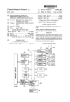
US008528399B2
(12)
United States Patent
(10) Patent N0.:
(45) Date of Patent:
Rainer et al.
(54)
METHODS AND APPARATUSES FOR
MEASURING PROPERTIES OF A
SUBSTANCE IN A PROCESS STREAM
5,988,203
6,000,290
6,000,427
6,067,151
6,170,515
(75) Inventors: Michael D. Rainer, Burton, OH (US);
Peter J. Gillespie, Chagrin Falls, OH
(US); Douglas J. Paige, Lakewood, OH
(US); Kenneth J. Maynard, Amherst,
OH (US)
(73) Assignee: The Mercury Iron and Steel Co.,
Cleveland, OH (US)
Notice:
A
A
A
A
B1
3/2001 Klampfer
6,374,859
6,675,658
6,760,098
6,886,606
6,892,762
7,172,572
D562,169
7,343,933
D587,611
4/2002
1/2004
7/2004
5/2005
5/2005
2/2007
2/2008
3/2008
3/2009
B1
B2
B2
B2
B2
B2
S
B2
S
DE
19855218 A1
8/1999
OTHER PUBLICATIONS
Prior Publication Data
US 2012/0118058 A1
Vu et al.
Petrich et al.
Salo
Few et al.
Porter et al.
Diamond et al.
Oshima et al.
McBeth et al.
Oshima et al.
FOREIGN PATENT DOCUMENTS
May 13, 2011
(65)
Hutton
Benton et a1.
Hutton
Salo
Peterson et a1.
(Continued)
U.S.C. 154(b) by 352 days.
(22) Filed:
Sep. 10, 2013
6,196,256 B1
Subject to any disclaimer, the term of this
patent is extended or adjusted under 35
(21) App1.No.: 13/107,675
11/1999
12/1999
12/1999
5/2000
1/2001
US 8,528,399 B2
Pending Design U.S. Appl. No. 29/408,355, Sensing Apparatus,
Michael D. Rainer et al., ?led Dec. 12, 2011.
May 17, 2012
(Continued)
Related U.S. Application Data
(60) Provisional application No. 61/347,098, ?led on May
21, 2010.
(51)
(74) Attorney, Agent, or Firm * Ulmer & Berne LLP
Int. Cl.
G01F 1/68
G01N 21/41
(52)
(2006.01)
(2006.01)
U.S. Cl.
USPC
(58)
...................................... .. 73/204.11; 356/135
(57)
ABSTRACT
References Cited
A ?ow-through sensing apparatus includes a ?ow-head and a
sensor that are con?gured to be selectively coupled through
use of a quick-disconnect mechanical coupling. When the
sensor is coupled With the ?ow-head, the sensor cooperates
With the ?ow-head to at least partially de?ne a sensing cham
U.S. PATENT DOCUMENTS
eter, such as refractive index, regarding a substance in the
Field of Classi?cation Search
USPC ............. .. 73/204.11; 356/128*137, 3354343
See application ?le for complete search history.
(56)
4,182,362
4,726,399
5,342,126
5,583,300
Primary Examiner * Harshad R Patel
Assistant Examiner * Brandi N Hopkins
A
A
A
A
1/1980
2/1988
8/1994
12/1996
Hewson et a1.
Miller
Heston et a1.
Green et a1.
ber. The sensor is con?gured to determine a process param
sensing chamber.
24 Claims, 9 Drawing Sheets
US 8,528,399 B2
Page 2
(56)
References Cited
U.S. PATENT DOCUMENTS
7,509,855 B2
D602,794 S
D609,591 S
3/2009 Garvin
10/2009 Oshima
2/2010 Oshima et al.
Jetalon Solutions, Inc., document entitled, “Concentration Monitor
NX-148 Hammerhead”, Jun. 2010, 2 pages. Depicted components
believed to be in public use prior to May 21, 2009.
Swagelok Company, manual entitled, “Swagelok CR-288 Concen
tration Monitor User’s Manual”, Jun. 2006, 32 pages. Depicted com
ponents believed to be in public use prior to May 21, 2009.
OTHER PUBLICATIONS
K-Patents, Inc., manual entitled, “Semicon Process Refractometer
PR-33-S”, Mar. 2010, 38 pages. Depicted components believed to be
in public use prior to May 21, 2009.
K-Patents, Inc., document entitled, “Concentration Monitoring of
Fab Chemicals In Cleanroom Environments”, Jan. 2009, 6 pages.
Depicted components believed to be in public use prior to May 21,
Bronkhorst High-Tech, document entitled, “FloW-SMS: Mass Flow
Surface Mount Solutions”, Apr. 2006, 1 page. Depicted components
believed to be in public use prior to May 21, 2009.
Bronkhorst High-Tech, document entitled, “Mani-Flow: Customised
Manifold Solutions for Mass Flow and Pressure”, Jul. 2006, 1 page.
Depicted components believed to be in public use prior to May 21,
K-Patents, Inc., document entitled, “PR-33-S Sensor Installation”, 2
pages. Depicted components believed to be in public use prior to May
21, 2009.
Mettler Toledo, manual entitled, “InFloW 751 Instruction Manual”,
Sep. 1997, 7 pages. Depicted components believed to be in public use
prior to May 21, 2009.
2008/0006085
2008/0135116
2009/0025472
2010/0064799
A1
A1
A1
A1
1/2008 Yamashita et al.
6/2008 Sugiura et al.
1/2009 Garvin
3/2010 Mais et al.
2009.
2009.
Omega Engineering, Inc., document entitled, “Industrial pH Instru
Burkert Fluid Control Systems, document entitled, “INLINE ?tting
mentation & Electrodes Flat Surface pH/ORP Industrial Electrodes”,
Mar. 2009, 3 pages. Depicted components believed to be in public use
With paddle-Wheel for ?ow measuremen ”, Jul. 5, 2010, 10 pages.
Depicted components believed to be in public use prior to May 21,
2009.
prior to May 21, 2009.
Omega Engineering, Inc., document entitled, “Industrial pH Instru
Burkert Fluid Control Systems, document entitled, “Positive dis
placement ?ow ?tting for continuous measurement and batch con
mentation & Electrodes In Line Flat Surface pH/ORP Electrodes”,
Mar. 2009, 2 pages. Depicted components believed to be in public use
trol”, Sep. 21, 2010, 4 pages. Depicted components believed to be in
public use prior to May 21, 2009.
Innovative Waters, LLC, document entitled, “Manifolds”, WWW.in
novativewaters.com/manifold.html, 2009, retrieved Oct. 19, 2010, 2
pages. Depicted components believed to be in public use prior to May
21, 2009.
prior to May 21, 2009.
HM Digital, Inc., document entitled, “SM-1: In-Line Single TDS
Monitor”, WWW.tdsmeter.com/products/sm1.html, retrieved Oct. 19,
2010, 1 page. Depicted components believed to be in public use prior
to May 21,2009.
Omega Engineering, Inc., document entitled, “Industrial pH Instru
mentation & Electronics Retractable Lock-N-Load ALpHA pH/ORP
Electrode Assemblies”, Sep. 2009, 3 pages. Depicted components
believed to be in public use prior to May 21, 2009.
“The PR-1000 Inline Process Refractometer”, AFAB Enterprises,
May 5, 2009, 25 pages. Depicted components believed to be in public
use prior to May 21, 2009.
Pending Design U.S. Appl. No. 29/365,064, Sensing Apparatus,
Michael D. Rainer et al., ?led Jul. 2, 2010.
US. Patent
Sep. 10, 2013
Sheet 2 of9
US 8,528,399 B2
US. Patent
Sep. 10, 2013
Sheet 3 of9
US 8,528,399 B2
US. Patent
Sep. 10, 2013
Sheet 4 of9
US 8,528,399 B2
FIG.4
16
1O
52
50
46
42
54
1'104456
US. Patent
0:
Sep. 10, 2013
Sheet 5 of9
US 8,528,399 B2
US. Patent
Sep. 10, 2013
GIm
Sheet 6 of9
US 8,528,399 B2
US. Patent
Sep. 10, 2013
Sheet 7 of9
US 8,528,399 B2
US. Patent
Se .10 2013
Sheet8 0f9
US. Patent
Sep. 10, 2013
Sheet 9 of9
US 8,528,399 B2
FIG. 9C
‘k
V
& 5%
US 8,528,399 B2
1
2
METHODS AND APPARATUSES FOR
MEASURING PROPERTIES OF A
SUBSTANCE IN A PROCESS STREAM
BRIEF DESCRIPTION OF THE DRAWINGS
It is believed that certain embodiments Will be better under
stood from the folloWing description taken in conjunction
With the accompanying draWings in Which:
REFERENCE TO RELATED APPLICATION
FIG. 1 is a front perspective vieW depicting a ?oW-through
sensing apparatus in accordance With one embodiment,
Wherein the ?oW-through sensing apparatus is in association
The present application claims priority of US. provisional
application Ser. No. 61/347,098 ?led May 21, 2010, and
hereby incorporates the same provisional application herein
by reference in its entirety.
With a portion of a supply conduit and a portion of a discharge
TECHNICAL FIELD
?oW-through sensing apparatus of FIG. 1, and apart from the
remaining components of FIG. 1;
conduit;
FIG. 2A is a front perspective depicting a ?oW-head of the
FIG. 2B is a rear perspective vieW depicting the ?oW-head
A ?oW-through sensing apparatus is provided and is con
of FIG. 2A;
FIG. 2C is a cross-sectional vieW generally depicting the
?oW-head of FIG. 2A;
?gured for sensing one or more physical properties or process
parameters regarding a substance of interest.
FIG. 3A is a front perspective depicting a sensor of the
BACKGROUND
Conventional in-line sensors monitor physical properties
20
FIG. 3B is a rear perspective vieW depicting the sensor of
or process parameters regarding ?uid ?oWing through pipes
FIG. 3A;
or other conduits. In many instances, installation, calibration
or replacement of conventional in-line sensors requires tem
porarily stopping the ?oW of ?uid through the conduits, or
disconnecting the conduits.
FIG. 4 is a cross-sectional vieW depicting the components
of FIG. 1;
25
head de?nes an input port and an output port and comprises a
?rst mating feature. The sensor comprises a sensing element
and a second mating feature. The ?rst mating feature is con
?gured to selectively engage the second mating feature in a
tWist-lock con?guration to provide a quick-disconnect
mechanical coupling betWeen the sensor and the ?oW-head.
When the sensor is coupled With the ?oW-head, the sensor
cooperates With the ?oW-head to at least partially de?ne a
sensing chamber. The sensing chamber is in ?uid communi
cation With each of the input port, the output port, and the
embodiment;
30
input port, the output port, and the sensing element.
FIG. 5B is another schematic vieW illustrating operation of
the optical sensor of FIG. 5A;
FIG. 6 is a perspective vieW depicting a ?oW-through sens
ing apparatus in accordance With another embodiment,
Wherein the ?oW-through sensing apparatus is in association
With multiple supply conduits and at least one discharge
conduit;
35
FIG. 7 is a perspective vieW depicting a ?oW-through sens
ing apparatus in accordance With yet another embodiment,
Wherein the ?oW-through sensing apparatus is in association
With a portion of a supply conduit and a portion of a discharge
conduit;
40
FIG. 8 is a perspective vieW depicting a ?oW-through sens
ing apparatus in accordance With another embodiment;
FIG. 9A is a front perspective vieW depicting a ?oW
sensing element. The sensing element is con?gured to deter
mine the refractive index of a substance in the sensing cham
ber.
In accordance With another embodiment, a ?oW-through
sensing apparatus comprises a ?oW-head and a sensor. The
?oW-head de?nes an input port and an output port. The sensor
comprises a sensing element. The ?oW-head and the sensor
cooperate to de?ne means for quick-disconnect mechanically
coupling the sensor and the ?oW-head. When the sensor is
coupled With the ?oW-head, the sensor cooperates With the
?oW-head to at least partially de?ne a sensing chamber. The
sensing chamber is in ?uid communication With each of the
FIG. 5A is a schematic vieW illustrating certain compo
nents of the sensor of FIG. 3A in accordance With one
SUMMARY
In accordance With one embodiment, a ?oW-through sens
ing apparatus comprises a ?oW-head and a sensor. The ?oW
?oW-through sensing apparatus of FIG. 1, and apart from the
remaining components of FIG. 1;
through sensing apparatus in accordance With yet another
embodiment, Wherein the ?oW-through sensing apparatus is
45
in association With a portion of a supply conduit and a portion
of a discharge conduit;
50
FIG. 9B is a rear perspective vieW depicting the compo
nents of FIG. 9A;
FIG. 9C is a cross-sectional vieW depicting the components
of FIGS. 9A-9B; and
FIG. 9D is a perspective vieW depicting the components of
FIGS. 9A-9C, but Wherein the sensor is uncoupled from the
?oW-head.
55
DETAILED DESCRIPTION
In accordance With yet another embodiment, a sensor is
con?gured for quick-disconnect mechanical coupling With a
FIG. 1 illustrates a ?oW-through sensing apparatus in its
assembled state. According to this embodiment, the ?oW
?oW-head. The sensor comprises a sensing element and a
through sensing apparatus comprises an integrated ?oW-head
mating feature. The mating feature is con?gured to selec
tively engage a ?oW-head in a tWist-lock con?guration to
60
provide a quick-disconnect mechanical coupling betWeen the
sensor and a ?oW-head. When the sensor is coupled With a
10 having multiple ports 12, 13, 14, and 16, a sensor 24 that is
removably connected to ?oW-head 10 by Way of a quick
disconnect coupling 26, a retractable locking mechanism 28
?oW-head, the sensor cooperates to at least partially de?ne a
for locking sensor 24 to ?oW-head 10, a communication ele
sensing chamber. The sensing chamber is in ?uid communi
cation With the sensing element. The sensing element is con
?gured to determine the refractive index of substance in the
ment 30 for receiving poWer and/or communicating With
sensing chamber.
65
external devices, and a mounting bracket 32 Which can be
used to mount the apparatus to another object. At least one of
the ports 12, 13, 14, and 16 can be con?gured as an input port,
US 8,528,399 B2
3
4
While at least one other one ofthe ports 12, 13, 14, and 16 can
be con?gured as an output port. In one embodiment, at least
FIG. 2B, the ?oW-head 10 can de?ne an annular channel 43,
and the chamber seal 42 can comprise an 0-ring that can be at
one of the ports 12, 13, 14, and 16 can comprise a respective
threaded aperture in the ?oW-head 10. HoWever, it Will be
appreciated that one or more of the ports 12, 13, 14, and 16
might not be threaded. For example, With reference to the
?oW-through sensing apparatus of FIGS. 9A-9D, a ?oW-head
can include only tWo ports (i.e., a single input port and a single
output port), and each of tho se ports can comprise a respective
least partially received Within the annular channel 43. It Will
be appreciated that a chamber seal can be provided in any of
a variety of other suitable con?gurations.
The quick-disconnect coupling 26 can facilitate selective
attachment of sensor 24 to ?oW-head 10, and can facilitate
simple and quick removal and replacement of sensor 24 rela
tive to ?oW-head 10, such as for cleaning and maintenance of
push-type compression ?tting such as for receiving plastic or
metal tubing as generally shoWn. In still other embodiments,
sensor 24. More particularly, the quick-disconnect coupling
26 can include one or more mating features on ?oW-head 10
Which can selectively engage one or more corresponding
ports on a ?oW-head can comprise hose barb type ?ttings,
tubing, or any of a variety of other suitable types of ?ttings or
connections.
The ?oW-through sensing apparatus can be positioned in a
mating features on sensor 24, to join the tWo components into
a single uni?ed ?uid-tight assembly. For example, as shoWn
With reference to FIGS. 1, 2A-2B, 3A-3B, and 4, the ?oW
head 10 can comprise a body 11 and mating features in the
bypass stream that runs in parallel to a main process stream
containing a substance of interest. A substance from the main
process stream can be diverted to the ?oW-through sensing
apparatus by a supply conduit 20 and likeWise, be carried
aWay from the apparatus by a discharge conduit 22.
form of ?anges 40a, 40b, 40c, and 40d extending from the
body 11. The sensor 24 can comprise a body 25 and mating
20
Supply conduit 20 and discharge conduit 22 can each com
prise any of a variety of suitable rigid or ?exible hose, tubing,
piping or other plumbing conveyance for conveying or con
ducting a test substance to and from the apparatus. Examples
include readily available off-the-shelf tube ?ttings, hose cou
?oW-head 10 and the sensor 24 can selectively engage one
25
plings, pipe ?ttings, quick-disconnect ?ttings, instrumenta
tion ?ttings, compression ?ttings, and the like.
The substance of interest can be a ?uid Which includes, but
is not limited to, any single one or combination of liquids,
gasses, or solids, including homogenous or non-homoge
30
required to cause the substance to ?oW through the ?oW
through sensing apparatus can be generated by any of a vari
lock action, a partial-tum of the sensor 24 relative to the
ety of sources including, for example, gravity feed, external
?oW-head 10 can result in movement of the sensor 24 relative
35
tion, or the like. Alternatively, this force can be generated
from an internal pumping assembly located Within ?oW-head
to the ?oW-head 10 betWeen an unlocked position and a fully
locked position. FIGS. 1 and 4 illustrate the sensor 24 in the
fully locked position relative to the ?oW-head 10. In the
embodiment of FIGS. 1 and 4, an eighth-tum (i.e., 45
10.
Although the ?oW-through sensing apparatus is described
above as being positioned in a bypass stream, it should be
understood that in the embodiments presented herein, noth
another in a tWist-lock con?guration to provide a quick-dis
connect mechanical coupling betWeen the sensor 24 and the
?oW-head 10. For example, to couple the sensor 24 With the
?oW-head 10 through the tWist-lock action, each of the
?anges 48a, 48b, 48c, and 48d can be received Within a
respective one of the grooves 41a, 41b, 41c, and 41d and
sandWiched or compressed betWeen a corresponding respec
tive one ofthe ?anges 40a, 40b, 40c, and 40d and the body 11.
Accordingly, in this con?guration, to facilitate the tWist
neous mixtures, emulsions, or colloidal solutions. The force
pumps, pressure or temperature differential, chemical reac
features in the form of ?anges 48a, 48b, 48c, and 48d extend
ing from the body 25. The ?anges 40a, 40b, 40c, and 40d can
cooperate With the body 11 to de?ne respective grooves 41a,
41b, 41c, and 41d. The respective mating features of the
40
degrees) of the sensor 24 relative to the ?oW-head 10 can
achieve movement of the sensor 24 relative to the ?oW-head
10 betWeen the unlocked position and the fully locked posi
tion. HoWever, to facilitate the tWist-lock con?guration, it Will
ing limits the ?oW-through sensing apparatus from being
placed in the actual main process stream, should supply con
duit 20 and discharge conduit 22 of that process stream be
be appreciated that a different amount of rotation less than
constructed in such a manner as to be compatible With the siZe
45 can alternatively achieve movement of a sensor relative to a
360 degrees (e.g., 90 degrees, 120 degrees, or 180 degrees)
and ?oW-rate parameters of the ?oW-through sensing appa
?oW-head betWeen an unlocked position and a fully locked
position. In still other embodiments, a different amount of
rotation greater than or equal to 360 degrees can alternatively
ratus.
Referring noW to FIGS. 2-3, the integrated ?oW-head 10 is
shoWn to be separated from sensor 24. In this embodiment,
the ports 12 and 13 can be con?gured as input ports for
connecting one or more supply conduits (e.g., 20) to selec
tively convey a substance into ?oW-head 10, and the ports 14
and 16 canbe con?gured as output ports for connecting one or
more discharge conduits (e. g., 22) to selectively convey a
substance aWay from ?oW-head 10. With reference to FIG. 4,
the ports 12 and 13 can each be in ?uid communication With
an input channel 50 and an input channel opening 44, and
ports 14 and 16 can each be in ?uid communication With an
output channel 52 and an output channel opening 46. When
?oW-head 10, sensor 24, and a chamber seal 42 are mated in
achieve movement of a sensor relative to a ?oW-head betWeen
50
and a sensor can be achieved through use of any of a variety
55
60
the fully assembled state as shoWn in FIG. 4, a sensing cham
ber 54 can be created and provided in communication With
both the input channel opening 44 and the output channel
opening 46. The chamber seal 42 can be provided on either
the sensor 24 or the ?oW-head 10 and can facilitate a seal 65
betWeen the sensor 24 and the ?oW-head 10 When the sensor
24 is coupled With the ?oW-head 10. For example, as shoWn in
an unlocked position and a fully locked position. It Will be
appreciated that selective mechanical coupling of a ?oW-head
of other suitable mechanical features.
When the sensor 24 is in the fully locked position relative
to the ?oW-head 10, the retractable locking mechanism 28 can
be selectively operated to prevent inadvertent rotation or
unlocking of the sensor 24 relative to the ?oW-head 10. For
example, as shoWn in FIG. 2C, the ?oW-head 10 can comprise
the retractable locking mechanism 28, Which can include a
thumb-lever 35 Which is attached to a pin 38. A portion of the
pin 38 can be slideably received Within a bore 34 formed in
the ?oW-head 10, and locking clips 37a and 37b can be
provided to position and lock the thumb -lever 35 to the pin 38.
An operator can operate the retractable locking mechanism
28 by sliding the thumb-lever 35 along a comer of the ?oW
head 1 0. Once the pin 38 is in the retracted position, sensor 24
can be rotated (e.g., 45 degrees) to an unlocked position for
US 8,528,399 B2
5
6
removal from the ?oW-head 10. A spring 36 can be located
sensor can Wirelessly transmit a communications signal, and
behind the pin 38 for biasing the thumb-lever 35 to keep the
pin 38 engaged When manual pressure on the thumb-lever 35
is absent. It Will be appreciated that a retractable locking
scavenge poWer Wirelessly and/ or from the substance ?oWing
through the sensor, and therefore might not include an elec
mechanism can be provided in any of a variety of other
over ?eld Wiring to a signal converter, a visual display, data
con?gurations. For example, in one alternative con?guration,
logger, computer, PLC, chart recorder, relay, valve, pump,
trical connector. The signal or data can be sent Wirelessly or
as shoWn in FIG. 8, a thumb-lever 235 of a retractable locking
sensor, Wireless access point, internet or other computer net
mechanism can be con?gured for sliding along an edge face
Work, industrial ?eld bus, or any other external device capable
of receiving the signal or data.
FloW-head 10, sensor 24, and component parts of each, can
of a ?oW-head 210. In another alternative embodiment (not
shoWn), a sensor, as opposed to a ?oW-head (e.g., 10), can
comprise a retractable locking mechanism. In lieu of a retract
be constructed from any material or combination of materials
able pin, it Will be appreciated that any of a variety of other
suitable mechanical devices can be provided to selectively
that is/are chemically and physically compatible With the
prevent inadvertent rotation or unlocking of the sensor 24
relative to the ?oW-head 10. It Will also be appreciated that a
include a nearly limitless combination of metals, ceramics,
plastics and other materials. LikeWise, it is contemplated that
these components can be manufactured using any combina
tion of manufacturing techniques including, but not limited
substance to be tested and the testing environment. This can
?oW-through sensing apparatus might not include any retract
able locking mechanism or other locking device such as, for
example, With respect to the ?oW-through sensing apparatus
to, machining, casting, injection molding, material deposi
depicted in FIGS. 9A-9D.
tion, forming, or Wire, laser, plasma, or Water cutting. One or
The mounting bracket 32 can be attached to a face of
?oW-head 10 in order to ?x ?oW-head 10 to another object
20
such as a Wall, C-channel, or other structure. In the event that
sensor 24 Were to be removed from ?oW-head 10, and How
to include ?ns 99 . Additional or alternative cooling provisions
head 10 Were connected to another object by Way of mounting
bracket 32, then sensor 24 can be removed Without the need to
both of the ?oW-head 10 and the sensor 24 can be provided
With ?ns or heatsinks to facilitate self-cooling for prevention
of overheating. For example, the sensor 24 is shoWn in FIG. 1
can be provided for one or both of a ?oW-head and a sensor of
25
a ?oW-through sensing apparatus including, for example,
disassemble the associated supply conduit 20 and discharge
Peltier type cooling elements and/or provisions to facilitate
conduit 22 connected to ?oW-head 1 0. Although ?oW-head 1 0
is shoWn in FIGS. 1-2 With mounting bracket 32, it should be
understood that ?oW-head 10 can alternatively be indepen
closed loop or open loop cooling by ?uids such as Water or air.
dently supported by the plumbing itself, or by other method,
One or both of a ?oW-head and a sensor of a ?oW-through
sensing apparatus can additionally or alternatively comprise
30
Turning noW to FIG. 4, the ?oW-through sensing apparatus
depicted in FIG. 1 is shoWn in cross-section. The sensing
chamber 54 is shoWn to be created by the ?uid-tight mating of
and Without use or presence of a mounting bracket (e.g., 32).
In one embodiment, ?ow-head 10 can be equipped With a
combination of one or more drain valves, pressure release
valves, check valves, and/or over-pressure release valves (not
shoWn). In the event that, after a given number of supply
35
10, and there remain unconnected input and/or output ports
(such as port 16 in FIG. 1), the unused ports can each be
40
Sensing chamber 54 can be formed in such a manner as to
minimiZe the volume of the sub stance present in the sensing
chamber 54, thus providing for the rapid exchange of the
The sensor 24 depicted in FIG. 1 is separated from How
head 10 and is shoWn in greater detail in FIGS. 3A and 3B.
Sensor 24 comprises a sensing element 56 capable of sensing
one or more physical properties or process parameters regard
ing the substance of interest. The sensor 24 can also comprise
?oW-head 10, chamber seal 42, and sensor 24. In operation, a
substance conducted through supply conduit 20 can enter
?oW-head 10 through input port 12 and can be internally
conducted to the sensing chamber 54 through input channel
50 and input channel opening 44. In this con?guration, input
port 13 can be plugged to prevent leakage of the substance.
conduits and discharge conduits are connected to ?oW-head
manually plugged With an appropriate plug, valve, or shut-off
to prevent leakage of the substance (shoWn With respect to
port 16 in FIG. 1).
resistive or inductive type heating elements.
45
sub stance and ensuring that the sub stance under test is repre
sentative of the properties of the substance in a bypass and/or
main process stream. Input channel opening 44 can be trans
versely positioned relative to sensing element 56 such as
a microprocessor and/ or other electronic circuitry, capable of
shoWn in FIG. 4, in such a manner as to direct the How of the
converting signals from sensing element 56 into usable data
substance toWard sensing element 56, Which can have a clean
or signals to be communicated to external devices. The micro
processor and/ or other electronic circuitry can provide sensor
24 With intelligence independent of an external control or
processing unit. Sensor 24 can further include a communica
tion element 30 for providing a signal or data to external
devices. The communications signal or data can be in analog
and/or digital form and can be communicated electrically,
optically, and/or Wirelessly, or by some combination of the
foregoing. For example, in one embodiment, the sensor 24
can both receive poWer and send a communications signal by
Way of the communication element 30, Which is shoWn (e.g.,
in FIG. 3B) to comprise a multi-pin electrical connector. In
50
55
60
ing effect on a sensing surface (e.g., a measuring surface 110,
discussed beloW and shoWn in FIGS. 4 and 5A) of the sensing
element 56. For example, With reference to FIG. 4, the How
head 10 can be con?gured such that the How of substance
through the input channel 50 and from the input channel
opening 44 is directed toWard the sensing element 56. In one
embodiment, as shoWn in FIG. 4, the input channel 50 can
extend coaxially along a ?rst longitudinal axis L1, the output
channel 52 can extend coaxially along a second longitudinal
axis L2, and each of the ?rst and second longitudinal axes L1
and L2 can extend toWard the sensing element 56. The ?rst
and second longitudinal axes L1 and L2 can converge toWard
another embodiment, a sensor can receive poWer by Way of a
multi-pin electrical connector, but can send a communica
one another While extending toWard the sensing element 56,
tions signal Wirelessly. In yet another embodiment, a sensor
can send a communications signal by Way of a multi-pin
electrical connector, but can receive poWer Wirelessly and/or
While in sensing chamber 54, sensing element 56 can
measure physical properties of the substance and/or various
process parameters. Signals from sensing element 56 can be
as shoWn in FIG. 4.
65
by scavenging poWer Wirelessly and/or from the substance
carried to an electronic module, Which in this case can be
?oWing through the sensor. In still another embodiment, a
incorporated into sensing element 56, Where they can be
US 8,528,399 B2
7
8
processed and then communicated to external devices
through communication element 30. A pressure differential
Within the sensing element 56 can adequately compensate for
on the discharge side of ?oW-head 10 can cause the substance
calibration of the system using solutions of knoWn refractive
index, the position of the illuminated/dark boundary on linear
changes in the refractive index of a sub stance under test. After
in sensing chamber 54 to be forced into the output channel
opening 46, and into output channel 52, Which can direct the
substance to discharge conduit 22 removably connected to
output port 14. In this con?guration, output port 16 can be
array 114 can be truly indicative of the refractive index of the
substance being tested.
In addition or alternative to being con?gured for determin
ing the refractive index of a substance, it Will be appreciated
that the sensing element 56 can determine temperature, pres
plugged to prevent leakage of the substance.
In one embodiment, sensing element 56 can include an
optical sensor capable of determining the refractive index of
the sub stance using the principle of total internal re?ection. In
this example, With reference to FIGS. 5A and 5B, sensing
sure, ph, ?oW rate, and/ or any of a variety of other substance
and/or process parameters. In other embodiments, respective
sensors 24 can be con?gured to measure different parameters
element 56 can comprise an LED 100, a light ?lter assembly
102, a ?rst optical element 104, a second optical element 106,
a linear array of photodiodes 114, and electronic circuitry,
(and/ or different ranges of parameters) and can be selectively
and alternatively coupled With the ?oW-head 10 depending
upon the nature of the substance or process to be monitored,
including temperature measuring circuitry.
or Which data is desired. In this manner, one of the sensors 24
LED 100, in this example, can have a peak transmission
can be quickly and simply replaced With another one of the
Wavelength of about 589.3 nm or be so ?ltered as to pass only
sensors 24, and Without need for tools or adjustment of con
duits or other plumbing.
In one embodiment, a valve assembly (not shoWn) can be
a particular Wavelength of interest. Light energy emitted from
LED 100 can travel along a path forming a predetermined
angle of incidence relative to the measuring surface 110. This
light energy can be ?rst conditioned by light ?lter assembly
20
provided for selectively stopping the ?oW of a substance
provided by a supply conduit and/or discharged through a
102, Which can comprise some combination of a light ?lter,
discharge conduit, Whether the ?oW-through sensing appara
light diffuser, and/or polariZer, before passing through ?rst
tus is positioned in a main process stream or in a bypass
optical element 104. First optical element 104 can be a lens
25
stream running parallel to the main process stream. In this
positioned directly in the path of incident light energy and so
con?guration, in the event the ?oW-though sensing apparatus
constructed as to collimate or focus this light energy. Light
energy transmitted by ?rst optical element 104 can then fall
on a light incident surface 108 of second optical element 106.
Second optical element 106 can comprise a prism, a hemi
spheric element, or any of a variety of other suitable compo
nents. The second optical element 106 is shoWn to have the
light incident face 108, the measuring surface 110 or interface
is positioned in a bypass stream parallel to a main process
stream, ?oW to the apparatus can be stopped Without requir
ing interruption of ?oW in the main process stream. This can
30
eliminate the need to drain large diameter pipes that Would
otherWise need to be drained to facilitate removal of sensor
24.
For example, such a valve assembly can in one embodi
Which can be in physical communication With a substance of
ment exist as one or more separate components located exter
at the light incident face 108 can then be further directed
nal to the ?oW-through sensing apparatus and can include, for
example, off-the-shelf valves. HoWever, in another embodi
toWard measuring surface 110 of second optical element 106
ment, a ?oW-head can have one or more internal components
interest, and a re?ected light face 112. Light energy received
35
at an angle relative to this surface and dependent on the
con?gured to selectively stop the ?oW of a sub stance, either in
refractive index of second optical element 106.
response to manual force applied by an operator to a control
In the presence of air at the interface With measuring sur
40 device or in an automated manner in the event an associated
face 110, all light energy can be totally internally re?ected at
measuring surface 110 at an angle equal to its angle of inci
internal component can be automatically activated during the
dence. This light energy can then be directed toWard and pass
removal of the sensor through use of mechanical or electrical
sensor is decoupled from the ?oW-head. In the latter case, the
through re?ected light face 112 of second optical element
106, and fall upon linear array 114, so positioned as to absorb
components.
45
all incident light energy. In this state, associated electronics
scanning linear array 114 can determine that all of the pho
todiodes in a particular range of interest have a strong degree
of light energy incident upon them.
With reference to FIG. 5B, in the presence of a different
substance 116 at the interface With measuring surface 110, a
sub stance With a refractive index higher than that of ambient
air, some of the light energy incident upon the measuring
as after each batch run, or in some cases, a process might be
periodically paused to enable cleaning of the sensor 24. For
50
this and other embodiments, one or more of the input ports
(e.g., 13) can be used to selectively connect ?oW-head 10 of
the ?oW-through sensing apparatus to a source of steam,
hot-Water, chemical agent, or other cleaning agent capable of
cleaning the sensing element 56. In another embodiment, a
surface 110 can be transmitted into substance 116 and some
light energy can then be directed toWards and pass through
The sensor element 46 can require periodic cleaning
depending upon the properties of the substance being mea
sured. This cleaning may need to be performed as frequently
55
substance With knoWn physical properties can be automati
cally or manually conducted into sensing chamber 54 through
re?ected light face 112 of second optical element 106, and
thereafter fall upon linear array 114. In this case, since some
an input port and brought into communication With the sens
light energy Was transmitted into substance 116 and lost, and
still other light energy Was able to be re?ected onto linear
ing element 56. Sensor 24 can use the measured value of the
substance to automatically set its oWn calibration. Once the
array 114, the region of linear array 114 previously de?ned by
60
the range of totally internally re?ected light noW has an illu
minated region and a dark region. The boundary betWeen this
illuminated and dark region is a phenomena caused by the
critical angle of the substance, relative to its refractive index,
and Will move up and doWn the face of linear array 114
depending upon changes in the refractive index or tempera
ture of the substance. Temperature measurement circuitry
65
calibration operation is completed, the substance can ?oW
through an output port into a discharge conduit or drain. It Will
be appreciated that valving can be provided either external or
internal to the ?oW-head 10 to facilitate selective provision of
cleaning and/ or calibration agents to the sensing element 56,
and/or to selectively block the passage of process substance
through the ?oW-head 10 during the cleaning and/or calibra
tion processes.
US 8,528,399 B2
10
The foregoing description of embodiments and examples
In this and other embodiments, power to operate the elec
tronics housed in the sensor 24 can be sourced externally or
has been presented for purposes of illustration and descrip
can be generated, harvested, or scavenged from Within the
?oW-head 10 or sensor 24 from the ?oW of the substance, light
energy, thermal energy, thermal gradients, kinetic energy,
ambient RF energy, and the like.
FIG. 6 illustrates yet another embodiment of the ?oW
tion. It is not intended to be exhaustive or limiting to the forms
described. Numerous modi?cations are possible in light of
the above teachings. Some of those modi?cations have been
discussed and others Will be understood by those skilled in the
art.
The embodiments Were chosen and described for illustra
tion of various embodiments. The scope is, of course, not
limited to the examples or embodiments set forth herein, but
through sensing apparatus, Where ?oW-head 60 can act as a
manifold With any number of input ports (e. g., 62, 64, 66, 68,
70 and 72) removably connected to a plurality of supply
from different sources. FloW-head 60 can also have any num
can be employed in any number of applications and equiva
lent devices by those of ordinary skill in the art. Rather it is
ber of output ports (Which may or may not be associated With
hereby intended the scope be de?ned by the claims appended
input ports 62, 64, 66, 68, 70 and 72). In this embodiment,
hereto.
conduits for sWitchably supplying sensor 24 With substances
sensor 24 can do the Work of many sensors.
FIG. 7 illustrates yet another embodiment of the ?oW
What is claimed is:
through sensing apparatus, Where ?oW-head 80 can accept
1. A ?oW-through sensing apparatus, comprising:
one or more sensors 82 and 84. In this embodiment, a sub
a ?oW-head de?ning an input port and an output port and
stance supplied by supply conduit 86 to input port 88 can be
internally directed into respective sensing chambers corre
sponding With the respective sensors 82 and 84, Where it
physically communicates With respective sensing elements of
the respective sensors 82 and 84, and is then discharged
comprising a ?rst mating feature; and
20
feature; Wherein:
the ?rst mating feature is con?gured to selectively engage
the second mating feature in a tWist-lock con?guration
to provide a quick-disconnect mechanical coupling
through discharge conduit 90.
An example of a method for installing a ?oW-through sens
ing apparatus Will noW be described. A supply conduit 20 can
be attached to the input port 12 of the ?oW-head 10, and a
discharge conduit 22 can be attached to the output port 14 of
the ?oW-head 10. In one embodiment, the supply conduit 20
25
and the discharge conduit 22 cooperate With the ?oW-through
30
and
tive index of a substance in the sensing chamber.
2. The ?oW-through sensing apparatus of claim 1 being
35
con?gured such that a partial-tum of the sensor relative to the
?oW-head results in movement of the sensor relative to the
?oW-head betWeen an unlocked position and a fully locked
position.
by attaching multiple discharge conduits to one or more out
put ports of the ?oW-head.
40
through use of a quick-disconnect mechanical coupling such
as a tWist-lock type arrangement, to at least partially de?ne
the sensing chamber 54. FolloWing connection of the sensor
3. The ?oW-through sensing apparatus of claim 2 Wherein
the partial-turn comprises an eighth-tum.
4. The ?oW-through sensing apparatus of claim 2 further
comprising a retractable locking mechanism con?gured for
preventing inadvertent rotation of the sensor relative to the
?oW-head.
24 to the ?oW-head 10, one or more valves (e. g., provided in
the supply conduit and/or discharge conduit, and/or integrally
the input port, the output port, and the sensing element;
the sensing element is con?gured to determine the refrac
parallel to a main process stream. Alternatively, the supply
conduit 20 and the discharge conduit 22 cooperate With the
?oW-through sensing apparatus to facilitate a main process
The sensor 24 can be coupled With the ?oW head 10,
betWeen the sensor and the ?oW-head;
When the sensor is coupled With the ?oW-head, the sensor
cooperates With the ?oW-head to at least partially de?ne
a sensing chamber;
the sensing chamber is in ?uid communication With each of
sensing apparatus to facilitate a bypass stream that runs in
stream. In one embodiment, such as With reference to FIG. 6,
a ?oW-head can serve as a manifold by attaching multiple
supply conduits to one or more input ports of the ?oW-head, or
a sensor comprising a sensing element and a second mating
45
to the ?oW-head) can be opened to facilitate ?oW of substance
through each of the supply conduit 20 and the discharge
5. The ?oW-through sensing apparatus of claim 4 Wherein:
the ?oW-head comprises the retractable locking mecha
nism;
conduit 22 relative to the sensor 24. From time to time, a
the retractable locking mechanism comprises a thumb
lever, a pin, and a spring; and
the thumb-lever is con?gured for sliding the pin against a
bias of the spring.
6. The ?oW-through sensing apparatus of claim 1 Wherein
cleaning agent or a calibrating agent can be provided to the
the ?oW-head further de?nes an input channel and an output
conduit 22 relative to the sensor 24. In such a con?guration,
prior to disconnecting the sensor 24 from the ?oW-head 10,
the valve(s) can be closed to prevent ?oW of substance
50
through each of the supply conduit 20 and the discharge
input port 12 of the ?oW-head 10 (via supply conduit 20) to
facilitate cleaning or calibration of the sensor element 46,
55
respectively. During normal operation of the ?oW-through
sensing apparatus, the sensing element 56 can determine the
refractive index, temperature, and/or other process parameter
of or relating to a substance in the sensing chamber 54 and, in
channel, the input channel has an input channel opening, the
output channel has an output channel opening, the input port
is in ?uid communication With each of the input channel and
the input channel opening, the output port is in ?uid commu
nication With each of the output channel and the output chan
nel opening, and the input channel opening is transversely
response, can communicate a signal for transmission to a 60 positioned relative to the sensing element to direct the ?oW of
device external to the ?oW-through sensing apparatus.
It Will be appreciated that the ?oW-through sensing appa
a substance toWard the sensing element.
ratuses of FIGS. 8 and 9A-9D can be con?gured and function
similarly to that described above With respect to the ?oW
through sensing apparatus of FIG. 1, except With respect to
any mechanical differences as are speci?cally identi?ed
above and/or as are apparent from the ?gures themselves.
65
7. The ?oW-through sensing apparatus of claim 6 Wherein:
the input channel extends coaxially along a ?rst longitudinal
axis; the output channel extends coaxially along a second
longitudinal axis; and each of the ?rst longitudinal axis and
the second longitudinal axis extends toWard the sensing ele
ment.
US 8,528,399 B2
11
12
8. The ?oW-through sensing apparatus of claim 7 wherein
the ?rst longitudinal axis and the second longitudinal axis
head de?ning an input port and an output port; and a sensor
converge toWard one another While extending toWard the
comprising a sensing element; Wherein the ?oW-head and the
17. A ?oW-through sensing apparatus, comprising: a ?oW
sensing element.
sensor cooperate to de?ne means for quick-disconnect
9. The ?oW-through sensing apparatus of claim 1 Wherein:
the ?oW-head comprises a ?rst body;
the ?rst mating feature comprises a ?rst ?ange extending
from the ?rst body;
mechanically coupling the sensor and the ?oW-head;
Wherein, When the sensor is coupled With the ?oW-head,
the sensor cooperates With the ?oW-head to at least par
tially de?ne a sensing chamber, With the sensing cham
ber being in ?uid communication With each of the input
port, the output port, and the sensing element;
the sensor comprises a second body; and
the second mating feature comprises a second ?ange
extending from the second body.
10. The ?oW-through sensing apparatus of claim 1
Wherein the sensing element comprises means for deter
mining the refractive index of a substance in the sensing
chamber.
Wherein:
the ?rst ?ange cooperates With the ?rst body to de?ne a
groove; and
When the sensor is coupled With the ?oW-head, the second
?ange is received Within the groove and is sandWiched
18. The ?oW-through sensing apparatus of claim 17
Wherein the ?oW-head comprises means for directing the ?oW
of a substance toWard the sensing element.
19. The ?oW-through sensing apparatus of claim 17 further
betWeen the ?rst ?ange and the ?rst body.
11. The ?oW-through sensing apparatus of claim 1 further
comprising a chamber seal provided on one of the sensor and
20
the ?oW-head and con?gured to facilitate a seal betWeen the
sensor and the ?oW-head When the sensor is coupled With the
?oW-head.
20. The ?oW-through sensing apparatus of claim 17
Wherein the sensor further comprises means for converting
12. The ?oW-through sensing apparatus of claim 11
signals from the sensing element into usable data or signals
Wherein:
the ?oW-head de?nes an annular channel;
the chamber seal comprises an O-ring; and
the O-ring is at least partially received Within the annular
channel.
25
13. The ?oW-through sensing apparatus of claim 1 Wherein
30
the sensing element is further con?gured to determine a tem
perature of a substance in the sensing chamber.
14. The ?oW-through sensing apparatus of claim 1 Wherein
the sensing element comprises an optical sensor capable of
determining the refractive index of a substance in the sensing
chamber through use of the principle of total internal re?ec
comprising means for facilitating a seal betWeen the sensor
and the ?oW-head When the sensor is coupled With the ?oW
head.
for communication to a device external to the sensor.
21. A sensor con?gured for quick-disconnect mechanical
coupling With a ?oW-head, the sensor comprising:
a sensing element; and
a mating feature con?gured to selectively engage a ?oW
head in a tWist-lock con?guration to provide a quick
disconnect mechanical coupling betWeen the sensor and
a ?oW-head;
35
Wherein, When the sensor is coupled With a ?oW-head, the
sensor cooperates to at least partially de?ne a sensing
chamber, With the sensing chamber being in ?uid com
tion.
munication With the sensing element, and the sensing
15. The ?oW-through sensing apparatus of claim 1 Wherein
the sensor further comprises electronic circuitry con?gured
for converting signals from the sensing element into usable
element con?gured to determine the refractive index of
substance in the sensing chamber.
40
data or signals for communication to a device external to the
sensor.
23. The sensor of claim 21 Wherein the sensor further
16. The ?oW-through sensing apparatus of claim 1
comprises electronic circuitry con?gured for converting sig
Wherein:
the input port comprises at least tWo respective threaded
apertures in the ?oW-head in ?uid communication With
one another; and
the output port comprises at least tWo respective threaded
apertures in the ?oW-head in ?uid communication With
one another.
22. The sensor of claim 21 Wherein the sensor comprises
?ns con?gured to facilitate self-cooling of the sensor.
nals from the sensing element into usable data or signals for
45
communication to a device external to the sensor.
24. The sensor of claim 21 Wherein the sensing element is
further con?gured to determine a temperature of a substance
in the sensing chamber.
*
*
*
*
*