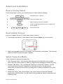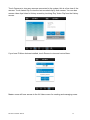
1
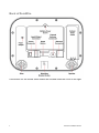
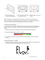
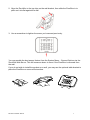
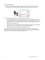
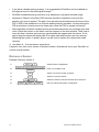
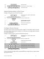
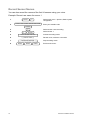
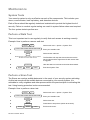
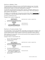
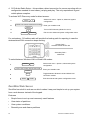
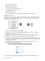
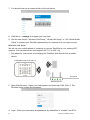
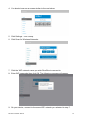
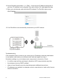
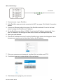
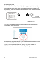
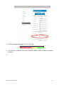
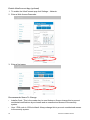
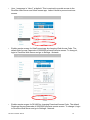
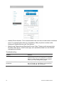
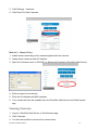
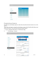
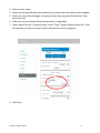
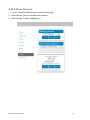
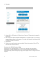
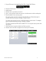
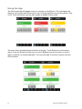
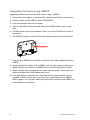
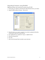
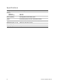
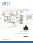
P/N 466-2520 • REV 01 • DRAFT 00.05
Copyright
Trademarks and
patents
Manufacturer
© 2014 UTC Fire & Security Americas Corporation, Inc.
All rights reserved.
This document may not be copied in whole or in part or otherwise
reproduced without prior written consent from UTC Fire & Security
Americas Corporation, Inc., except where specifically permitted
under US and international copyright law.
Trade names used in this document may be trademarks or
registered trademarks of the manufacturers or vendors of the
respective products.
Placed on the market by:
UTC Fire & Security Americas Corporation, Inc.
3211 Progress Drive, Lincolnton, NC, 28092, USA
Authorized EU manufacturing representative:
UTC Fire & Security B.V.
Kelvinstraat 7, 6003 DH Weert, Netherlands
EU compliance
EU directives
UTC Fire & Security hereby declares that this device is in
compliance with the applicable requirements and provisions of one
or more of the Directives 1999/5/EC, 2014/30/EU and 2014/35/EU.
For more information see: www.utcfireandsecurity.com.
2002/96/EC (WEEE directive): Products marked with this symbol
cannot be disposed of as unsorted municipal waste in the European
Union. For proper recycling, return this product to your local supplier
upon the purchase of equivalent new equipment, or dispose of it at
designated collection points. For more information see:
www.recyclethis.info.
2006/66/EC (battery directive): This product contains a battery that
cannot be disposed of as unsorted municipal waste in the European
Union. See the product documentation for specific battery
information. The battery is marked with this symbol, which may
include lettering to indicate cadmium (Cd), lead (Pb), or mercury
(Hg). For proper recycling, return the battery to your supplier or to a
designated collection point. For more information see:
www.recyclethis.info.
Contact information
Customer support
For contact information, see www.utcfireandsecurity.com
For customer support in EU, see www.utcfssecurityproducts.eu.
Content
Important information iii Limitation of liability iii Advisory messages iii Welcome 1 Features and benefits 1 Your new security system 2 Optional parts: 2 Front of ZeroWire 3 Back of ZeroWire 4 Install Your ZeroWire 5 What You Need 5 Choose a Location 5 Install the Battery 5 Install Cellular Radio 6 Install ZeroWire on Wall 6 Connect Power 8 Add Your Sensors 9 Unpack Sensors 9 Learning Sensors into ZeroWire 9 Install Sensor in Home 9 Remove a Sensor 10 Add Users and Keyfobs 11 Introduction 11 Add a User 11 Add a Key Fob 11 Remove a User 12 Change User Type 12 Customize Your ZeroWire 13 Volume Level 13 Voice Annunciation 13 Full Menu Annunciation 13 Backlight Level 14 Change Time and Date 14 Adjust Partition Entry or Exit Times 15 Configure Sensor Names 15 Record Sensor Names 16 Maintenance 17 System Tests 17 ZeroWire Installation Manual
i
Perform a Walk Test 17 Perform a Siren Test 17 Perform a Battery Test 18 Perform a Communicator Test 18 Advanced Installation 19 Reset to Factory Default 19 Reset Installer Account 19 Switch Connection Modes 19 ZeroWire Web Server 20 Connecting Inputs 31 Connecting Outputs 32 Changing Keyfob Options 34 Add IP Cameras 34 Viewing Cameras 35 Programming Cameras 36 View Camera Clips 38 Add Z-Wave Devices 39 Access via UltraConnect App 40 Using the App 42 DLX900 Software 45 System Status Messages 47 UltraConnect App Status and Error Messages 48 Voice Library 50 ZeroWire Menu Tree 51 Upgrading Firmware using USBUP 52 Upgrading Firmware using DLX900 53 Specifications 54 Index 55 ii
ZeroWire Installation Manual
Important information
Limitation of liability
To the maximum extent permitted by applicable law, in no event will UTCFS be
liable for any lost profits or business opportunities, loss of use, business
interruption, loss of data, or any other indirect, special, incidental, or
consequential damages under any theory of liability, whether based in contract,
tort, negligence, product liability, or otherwise. Because some jurisdictions do not
allow the exclusion or limitation of liability for consequential or incidental
damages the preceding limitation may not apply to you. In any event the total
liability of UTCFS shall not exceed the purchase price of the product. The
foregoing limitation will apply to the maximum extent permitted by applicable law,
regardless of whether UTCFS has been advised of the possibility of such
damages and regardless of whether any remedy fails of its essential purpose.
Installation in accordance with this manual, applicable codes, and the instructions
of the authority having jurisdiction is mandatory.
While every precaution has been taken during the preparation of this manual to
ensure the accuracy of its contents, UTCFS assumes no responsibility for errors
or omissions.
WARNING: The equipment should only be operated with an approved power
adapter with insulated live pins.
Caution: Risk of explosion if battery is replaced by an incorrect type. Dispose of
batteries according to the instructions. Contact your supplier for replacement
batteries.
Advisory messages
Advisory messages alert you to conditions or practices that can cause unwanted
results. The advisory messages used in this document are shown and described
below.
WARNING: Warning messages advise you of hazards that could result in injury
or loss of life. They tell you which actions to take or to avoid in order to prevent
the injury or loss of life.
Caution: Caution messages advise you of possible equipment damage. They tell
you which actions to take or to avoid in order to prevent the damage.
Note: Note messages advise you of the possible loss of time or effort. They
describe how to avoid the loss. Notes are also used to point out important
information that you should read.
ZeroWire Installation Manual
iii
Welcome
Thank you for purchasing ZeroWire!
ZeroWire can be set up in 4 steps and the voice guide will walk you through each
of the menus and settings.
1
2
Install your ZeroWire 3
Add your sensors 4
Add users & keyfobs
Customize your system Instead of using the keys on the front of ZeroWire, you can also set up the
system with the built-in web server interface using a browser (see "ZeroWire
Web Server" on page 20).
Please read through this guide before starting the installation.
Features and benefits
•
255 Users – enough for even moderate sized businesses
•
64 Sensors + 25 Keyfobs – provides a large coverage area
•
8 Partitions – split your system into smaller parts you can protect individually
•
Dynamic Key Lighting – lights up the available options to make it easier to
program
•
Personal Voice Guide – steps you through customizing your system
•
2 Inputs – integrate non-wireless devices to your security system
•
2 Programmable Outputs – connect other devices such as siren and strobe
•
Loud internal piezo siren – warns intruders they have been detected and
encourages them to leave quickly
•
Modern self contained unit – all in one box
•
Battery backup – your property is still protected if there is a loss of power
•
802.11 b/g WiFi – enables remote access via a web browser or smart phone
•
IEEE 802.3 Compliant Ethernet – use hardwired cable instead of wireless, the
choice is yours
•
3G Cellular radio support – allows reporting alarm messages without a fixed
line telephone service
ZeroWire Installation Manual
1
Your new security system
Check that everything is complete before beginning your installation. If anything
is missing please contact the customer service.
Installation
Manual
User
Manual
(this
document)
Reference
Guide
(online)
•
ZeroWire with Wall Bracket
•
9 VDC Power Pack
•
Backup Battery Pack
•
Input/Output Lead
•
Installation Manual (this document)
•
User Manual
•
Quick Reference Guide
Quick
Reference
Sheet
Optional parts:
•
ZW-ANT3M Extension Antenna
•
ZW-DS01
Desk Stand
•
ZW-HSPA
Cellular Modem
•
Wireless Sensors
•
Wireless Keyfobs
2
ZeroWire Installation Manual
Front of ZeroWire
Key
Colour
Description
Red
System is in alarm. Enter your
PIN code then ENTER to turn off
the alarm. Press STATUS key for
more info.
System is disarmed if Away is
also not lit. Press the STAY key
to arm in Stay mode.
System is armed in the “STAY”
mode.
System is normal.
ALARM Not lit
STAY Yellow
Green
Yellow
Red
STATUS (steady)
Non-urgent system conditions
present. Press the STATUS key
to hear system conditions.
Urgent system conditions
present.
Touch the STATUS key to hear system
messages. If you are unable to fix the issue,
contact your service provider for help.
System is disarmed if Stay is also
Not lit
AWAY Red
Not lit
READY not lit. Press the AWAY key to arm
in Away mode.
System is armed in the “AWAY”
mode.
System cannot be armed, press
STATUS key for more info.
ZeroWire Installation Manual
Key
Colour
Green
(steady)
READY Description
All sensors are ready and the
system can be armed in Away or
Stay mode.
Green
(flashing)
Sensors are currently unsealed but
system is force-armable. If these
sensors are not sealed by the end
of the exit time the system will go
into alarm.
Press the BYPASS key if you wish to isolate
(ignore) a sensor. Bypassed sensors will not
be active when you arm the system in Stay or
BYPASS Away modes.
Press the CHIME key to select which sensors
will make a doorbell sound on the ZeroWire
when they are tripped.
CHIME HISTORY Press the HISTORY key to listen for alarm
and event history.
Feature must be enabled by your security
provider. Check what response will be
FIRE provided. Hold down the key to send a
MEDICAL
message to a central monitoring centre.
POLICE Enter your PIN code then ENTER to turn off
a SOS alarm.
3
Back of ZeroWire
Connections for the cellular radio module are located under the cover on the right.
4
ZeroWire Installation Manual
Install Your ZeroWire
What You Need
•
ZeroWire and everything inside the box
•
Sensors and key fobs you will add
•
List of users and PIN codes you wish to add
•
Wall socket for powering ZeroWire
•
Small Phillips head screwdriver
•
Small Flathead screwdriver
•
Router supporting 802.11 b or 802.11g if using local WiFi features
•
Optional – desk stand
•
Optional – internal or external siren and strobe
Choose a Location
When choosing a location for your ZeroWire there are a number of appliances and areas
to avoid which could interfere with the security system.
•
Choose a central location for the best reception to all wireless sensors and Z-Wave
devices
•
If the ZeroWire Cellular Radio is installed select a location with sufficient signal
•
Avoid TV and other electronic appliances
•
Avoid microwave ovens
•
Avoid wet and moist partitions such as bathrooms and toilets
•
Avoid cordless telephones
•
Avoid computers and wireless equipment
Install the Battery
1. Loosen the screw from a bottom of ZeroWire, this will allow the wall bracket to be
removed from the unit.
ZeroWire Installation Manual
5
2. Remove battery cover
with a small screwdriver.
3. Connect battery pack lead 4. Replace battery cover and
to connector on left.
screw.
Note: The battery wire cannot be under the battery or the cover will not fit properly.
Note: The battery is not designed as a long-term power source. Plugging in the battery
should be followed quickly with the plugging in of the DC power supply.
Install Cellular Radio
If the ZeroWire Cellular Radio installation is planned it should be done before plugging in
the main DC power cord. Refer to the ZeroWire Cellular Radio installation Manual for
details.
1. Check the radio signal strength (see "3G Cellular Radio Setup" on page 26).
2. Ensure the Signal Strength is -87 to -51 dbm.
Too Low
-113
-107
OK
-98
-87
-76
-51
3. If it is too low, move the unit to the location with better signal or install an external
antenna.
Install ZeroWire on Wall
1. Install the bracket on a wall by using the supplied screws. Make sure the power lead
can reach the ZeroWire when plugged in to a power source.
6
ZeroWire Installation Manual
2. Align the ZeroWire to the top clips on the wall bracket, then slide the ZeroWire in to
place so it sits flat against the wall.
3. Use a screwdriver to tighten the screw you loosened previously.
You may enable the box tamper feature from the System Menu – General Options via the
ZeroWire Web Server. This will cause an alarm to occur if the ZeroWire is removed from
the wall.
If you do not wish to install the product on a wall, you may use the optional table bracket to
place the ZeroWire on a secure flat surface.
ZeroWire Installation Manual
7
Connect Power
1. Connect a DC power lead from power pack to the back of the ZeroWire, it only fits
when inserted in the correct direction. Make sure a correct polarity is observed.
2. Connect the power pack to its own power outlet and turn it on.
•
CAUTION: Wall tamper is an optional security feature that is disabled by default.
When enabled it will sound the siren when power is connected. Press 9 7 1 3 Enter
to turn the siren off. If this does not work, proceed to "Reset Installer Account" on
page 19 to enable this code.
•
Lights should be lit on the ZeroWire when the power is turned on. If not check that
the power lead is connected securely to the rear of the ZeroWire.
•
Avoid using multiple power adapters and power boards.
Note: ZeroWire should be connected to a power source at all times. The battery is a
backup power source, and the ZeroWire is designed to run on the battery pack during a
power failure only, and NOT for prolonged periods of time.
8
ZeroWire Installation Manual
Add Your Sensors
Unpack Sensors
These instructions are for general information only. Please refer to the manual included
with each sensor for further details.
1. Remove the sensor from packaging. 2. Remove a battery cover of the sensor. 3. Install batteries taking care to insert them correctly. Batteries inserted with reverse
polarity may damage the sensor. Learning Sensors into ZeroWire
Example: Add a PIR motion detector to ZeroWire and assign it as sensor 1.
1.
2.
MENU
5
YOUR 4 OR 6 DIGIT INSTALLER CODE
ENTER
1
3.
4.
Select Sensor Configuration.
Enter your Installer code.
Select 1 to add sensor.
Activate the sensor learn-in sequence (see specific
wireless sensor manual for instructions).
ZeroWire will announce that the sensor or keyfob is
detected.
PRESS DEVICE BUTTON
1
5.
6.
MENU
ENTER
MENU
Assign the sensor as sensor number 1, or just press
Enter to automatically assign a number. Press 1-6 for
the sensor group.
MENU
Exit from the menu.
Install Sensor in Home
1. Replace battery cover.
2. Install sensor in a suitable location. Here are some tips:
•
Wireless sensors feature low power transmission to maximize battery life. This means
you should place the ZeroWire in a central location and install sensors as close to the
ZeroWire as possible.
•
Signals from each sensor will reduce in strength as they pass through different building
materials with brick and concrete absorbing more of the signal.
•
Keep sensors away from household appliances and metal surfaces (e.g. refrigerator,
TV, washing machine, garage door). Metal surfaces will reflect the signal away.
ZeroWire Installation Manual
9
•
If you have a double-storey property, it is suggested the ZeroWire unit be installed on
the highest level for the best signal strength.
•
ZeroWire installed below ground level (e.g. basement) may have reduced range.
•
Movement / Passive Infra-Red (PIR) sensors should be installed to look over the
partition you want to protect. The path of an intruder should walk across the front of the
PIR. A PIR is less sensitive to an intruder walking directly towards it. Avoid pointing the
PIR at windows or heat sources as these may cause the PIR to operate incorrectly.
•
Reed switches should be installed across doors/windows where two surfaces open and
close. Place the sensor on the frame and the magnet on the door/window. Take care to
close the door / window and note any gap between the magnet and the sensor. If the
gap is large the sensor will always be in an open state and prevent you from arming /
disarming the system. A plastic spacer can be used to ensure the reed switch seals
correctly.
4. Use Menu 4 – 4 to test sensor signal level.
If signal is low, then move sensor to another location. Alternatively move your ZeroWire to
a more central location.
Remove a Sensor
Example: Remove sensor 8
MENU
1.
2.
5
YOUR 4 OR 6 DIGIT INSTALLER CODE
ENTER
3.
2
4.
2
8
5.
6.
10
Select Sensor Configuration.
MENU
Enter your Installer code.
Select 2 to remove sensor or keyfob.
Select 2 to remove sensor.
ENTER
MENU
Select the sensor number that needs to be removed.
MENU
Exit from Advanced system configuration.
ZeroWire Installation Manual
Add Users and Keyfobs
Introduction
ZeroWire allows you to add up to 255 users. Each user is assigned a PIN code and a user
number. This allows them to interact with the system.
Add a User
Example: Add a new user to ZeroWire and assign them a PIN code 2580. We will add this
as user 4.
1.
2.
MENU
3
YOUR 4 OR 6 DIGIT INSTALLER CODE
ENTER
1
3.
4
4.
2
8
MENU
Enter your Installer code.
Select 1 to configure user PIN.
ENTER
MENU
ENTER
5
5.
6.
Select User Configuration menu.
Select user 4.
0
Set user 4 PIN code as 2580.
MENU
Exit from Advanced system configuration.
Add a Key Fob
Example: Add a new key fob and assign it as sensor 65
1.
2.
MENU
5
Select Sensor Configuration.
YOUR 4 OR 6 DIGIT INSTALLER CODE
ENTER
3.
1
Select 1 to add a keyfob.
4.
65
6.
MENU
ZeroWire Installation Manual
ENTER
MENU
Enter your Installer code.
PRESS DEVICE BUTTON
5.
Select the number that will be assigned to this keyfob,
followed by Enter. Press Enter for the next keyfob.
MENU
Activate the keyfob learn-in sequence (see specific
wireless keyfob manual for instructions).
ZeroWire will announce that the keyfob is detected.
Exit from the menu.
11
Remove a User
Example: Remove user 4 from your system
MENU
1.
2.
3
YOUR 4 OR 6 DIGIT INSTALLER CODE
ENTER
3.
1
4
4.
MENU
MENU
Enter your Installer code.
Select 1 to configure user PIN.
ENTER
BYPASS
5.
6.
Select User Configuration menu.
Select user 4.
Press Bypass to disable the selected user's PIN code.
MENU
Exit from the menu.
Change User Type
Example: Change user 6 to a master user (installer) and allow to add/remove other users.
MENU
1.
2.
3
YOUR 4 OR 6 DIGIT INSTALLER CODE
ENTER
2
3.
4.
6
12
MENU
MENU
Enter your Installer code.
Select 2 to configure user type.
ENTER
2
5.
6.
Select User Configuration menu.
Select the user number.
Select 2 for the installer user type (available options:
1−Standard, 2−Installer, 3−Arm Only.).
MENU
Exit from the menu.
ZeroWire Installation Manual
Customize Your ZeroWire
Volume Level
Example: Set volume level to 6
1.
MENU
6
2.
3.
MENU
1
Select main menu - Option 1, Volume level.
Set volume level to 6.
MENU
Exit from the menu.
Voice Annunciation
Example: Turn on/off the voice when arming and disarming
1.
2.
MENU
8
YOUR 4 OR 6 DIGIT INSTALLER CODE
ENTER
4
MENU
Pressing [4] toggles voice annunciation on / off.
Pressing [5] toggles full menu annunciation on / off.
MENU
Enter your Installer code.
3.
4.
Select main menu - Option 8, Basic system
configuration.
Exit from the menu.
Full Menu Annunciation
Turning this feature On, gives full descriptions to all the options within the main menu.
Turning this feature Off shortens the descriptions.
1.
2.
MENU
8
YOUR 4 OR 6 DIGIT INSTALLER CODE
ENTER
5
3.
4.
Select main menu - Option 8, Basic system
configuration.
MENU
ZeroWire Installation Manual
Enter your Installer code.
Pressing [4] toggles voice annunciation on / off.
Pressing [5] toggles full menu annunciation on / off.
MENU
Exit from the menu.
13
Backlight Level
Example: Set run mode brightness level to 8
1.
MENU
1
2.
3.
4.
Select main menu – Option 2, Backlight level.
[1] Run mode backlight level
[2] Idle mode backlight level
8
MENU
2
Set brightness level to 8.
MENU
Exit from the menu.
Idle mode is when your ZeroWire is not being used. The lights on the screen dim for your
comfort at night. All security functions work normally. Pressing any button will bring the
LEDs back up for normal operation.
Example: Set idle mode brightness level to 1. (A default setting is zero so normally no
lights are on after the keypad light timer expires.)
1.
MENU
2
2.
4.
MENU
Select main menu – Option 2, Backlight level.
[1] Run mode backlight level.
[2] Idle mode backlight level
1
3.
2
Set brightness level to 1.
MENU
Exit from the menu.
Change Time and Date
Time and date are normally automatically updated with an internet time server.
Example: Setting the time as 9.30AM, and the date as 19.6.2014
1.
2.
MENU
8
YOUR 4 OR 6 DIGIT INSTALLER CODE
ENTER
1
3.
1
4.
5.
9
6.
30
8.
14
19
Enter your Installer code.
Select time and date configuration.
[1] To configure the time and date.
[2] To configure the date.
ENTER
ENTER
1
7.
Select main menu - Option 8, Basic system
configuration.
Enter the minutes value.
Press 1 for AM.
Press 2 for PM.
ENTER
Enter the hours value.
Enter the day.
ZeroWire Installation Manual
6
9.
10.
11.
2
0
MENU
ENTER
1
4
MENU
Enter the month.
ENTER
MENU
Enter the year, it must be 4 digits.
Exit from the menu.
Adjust Partition Entry or Exit Times
Example: Setting the entry time as 90 seconds
MENU
1.
2.
8
Select main menu - Option 8, Basic system
configuration.
YOUR 4 OR 6 DIGIT MASTER CODE
ENTER
2
9
5.
MENU
0
[2] Select partition entry time.
[3] Select partition exit time.
ENTER
Enter your Installer code.
3.
4.
MENU
Enter the new entry/exit time.
MENU
Exit from the menu.
Configure Sensor Names
All sensors can be named using library words on page 50. This makes it easier to identify
the correct sensor in the event of a condition. You may enter up to eight words to achieve
your desired description.
Example: Configure sensor 1 name as “Dining Room Sensor”
MENU
1.
8
Select main menu - Option 8, Basic system
configuration.
YOUR 4 OR 6 DIGIT INSTALLER CODE
2.
ENTER
4
3.
1
4.
5
5.
1
1
6.
MENU
1
2
3
Select sensor name recording.
ENTER
7
1
MENU
Enter your Installer code.
Select sensor 1.
ENTER
ENTER
ENTER
Select word “Dining” from the word library.
MENU
Select word “Room” from the word library.
Select word “Sensor” from the word library.
Exit from the menu.
If you do not require all eight words, just press MENU as in step 6 after you have entered
the last word number.
ZeroWire Installation Manual
15
Record Sensor Names
You can also record the names of the first 64 sensors using your voice.
Example: Record user name for sensor 1
MENU
1.
2.
8
YOUR 4 OR 6 DIGIT INSTALLER CODE
ENTER
3.
4
4.
16
1
ENTER
( ( SPEAK NAME ) )
7.
RELEASE HISTORY
MENU
Select sensor 1.
6.
Enter your Installer code.
Select sensor name recording.
HOLD DOWN HISTORY
MENU
5.
8.
Select main menu - Option 8, Basic system
configuration.
Activate recording mode.
Record voice, maximum 2 seconds.
MENU
Stop recording mode.
Exit from the menu.
ZeroWire Installation Manual
Maintenance
System Tests
Your security system is only as effective as each of the components. This includes your
sirens, communicator, back up battery, and detection devices.
Each of these should be regularly tested and maintained to provide the highest level of
security. Failure to conduct regular testing can result in system failure when most required.
The four system tests to perform are:
Perform a Walk Test
This is an important test to use regularly to verify that each sensor is working correctly.
Example: How to perform a sensor walk test
MENU
1.
2.
4
YOUR 4 OR 6 DIGIT INSTALLER CODE
ENTER
3.
4.
Select sensor walk test
Walk past each motion sensor, open and close windows and doors with sensors STATUS
MENU
MENU
Enter your Installer code.
4
5.
6.
Select main menu - Option 4, System Test
The ZeroWire will chirp the siren and announce the
sensor name and the signal level of each sensor that
is triggered.
Hear the status of each sensor that has been tested.
MENU
Exits from System Test
Perform a Siren Test
The Sirens are used as audible deterrents in the event of your security system activating.
As this test sounds all the audible devices connected to your security system, it is
advisable to notify neighbors and other persons within the premises prior to activating this
test. Using hearing protection is also recommended.
Example: How to perform a siren test
MENU
1.
2.
4
YOUR 4 OR 6 DIGIT INSTALLER CODE
ENTER
3.
1
4.
MUTE
5.
Select main menu - Option 4, System Test.
MENU
ZeroWire Installation Manual
MENU
Enter your Installer code.
Select siren test.
Press Mute to stop sirens (within 30 seconds).
MENU
Exit from the menu.
17
Perform a Battery Test
The backup battery is located on the rear of the ZeroWire behind a cover. It provides
temporary power to the ZeroWire when mains power is not available. This may occur
during a power outage or an intruder cutting power to a property.
The ZeroWire will automatically test the battery each day. If the battery fails then your
system can no longer protect your property in a power outage. This is why replacing it
when needed is very important.
The battery is a consumable part of the system and should be replaced every 3 years (to
be completed) or when the battery test fails (whichever is sooner). Contact your service
provider for replacement parts.
Example: How to perform a battery test
MENU
1.
2.
4
YOUR 4 OR 6 DIGIT INSTALLER CODE
ENTER
3
3.
4.
Select main menu - Option 4, System Test.
MENU
Select battery test.
MENU
MENU
Exit from the menu.
Perform a Communicator Test
The communicator is a part of the ZeroWire responsible for sending alarm messages. The
communicator test is only available if your security system has been set up to report to a
central monitoring station. Proper operation of this is very important for alarm reporting.
When testing your communicator, no sirens will sound and a test message will be sent to
the central monitoring station.
Example: Perform a communicator test
1.
Call your central monitoring station and
tell them you are performing a
communicator test.
MENU
2.
3.
4
YOUR 4 OR 6 DIGIT INSTALLER CODE
ENTER
Select communicator test.
2
5.
The central monitoring station will
confirm the test message was received.
7.
MENU
MENU
4.
6.
18
Select main menu - Option 4, System Test.
MENU
Exit from the menu.
If the communicator test fails, notify your
service provider.
ZeroWire Installation Manual
Advanced Installation
Reset to Factory Default
Follow these steps to reset your ZeroWire back to factory default settings:
MENU
1.
2.
9
YOUR 4 OR 6 DIGIT INSTALLER CODE
ENTER
0
3.
MENU
MENU
Enter your Installer code.
Select resetting to the factory defaults.
BYPASS
4.
5.
Select main menu - Option 9.
Confirm by pressing the BYPASS key, and then wait
for 10 seconds.
MENU
Exit from the menu.
Reset Installer Account
Lost your installer PIN code? Follow these steps to reset it:
1. Use a small screwdriver to hold down the reset button before you turn on power.
2. Wait 3 seconds after turning on the power, then release the reset button. This will reset
user 40 to PIN 9713 and username “installer”.
Switch Connection Modes
A few connection methods are supported:
1. WiFi Discovery Mode – this provides direct access to the ZeroWire from a mobile
device such as a smart phone or tablet for programming settings and initial set up only.
2. Wireless LAN Setup – this connects the ZeroWire to a local WiFi network. You will
need to provide an internet connection and wireless router for the permanent
connection. A mobile device such as a smart phone or tablet is needed to set up this
connection.
3. Wired LAN Setup – this is the easiest to set up but requires a physical Ethernet
connection to the ZeroWire. You will need to also provide the internet connection and
Ethernet router.
ZeroWire Installation Manual
19
4. 3G Cellular Radio Setup – this provides a direct connection for secure reporting with no
configuration needed in most cases, just plug and play. The only requirement is good
mobile phone reception.
To activate WiFi Discovery mode for direct access:
1.
MENU
9
Select main menu - Option 9, Advanced system
configuration.
YOUR 4 OR 6 DIGIT INSTALLER CODE
2.
ENTER
3.
8
MENU
4.
Turn on WiFi Discovery Mode for 10 min.
MENU
Enter your Installer code.
Exit from the Advanced system configuration menu.
For redundancy, 3G cellular radio will provide the backup path for reporting in case the
wireless/wired LAN connection stops working.
Primary Path –
wireless LAN or wired LAN
Secondary Path –
cellular 3G
To select between Wireless LAN or Wired LAN modes:
MENU
1.
2.
9
Select main menu - Option 9, Advanced system
configuration.
YOUR 4 OR 6 DIGIT INSTALLER CODE
ENTER
7
3.
4.
MENU
Enter your Installer code.
Toggle between Wireless LAN and Wired LAN
connection modes.
MENU
Exits from Advanced system configuration menu.
ZeroWire Web Server
ZeroWire has a built in web server which makes it easy and simple to set up your system
from a web browser instead of the keypad.
Features
•
Simple forms to set up most commonly used features
•
View status of partitions
•
View system conditions
•
Remotely arm and disarm partitions
20
ZeroWire Installation Manual
•
Turn chime mode on and off
•
Bypass/Un-bypass sensors
•
Add, remove and edit users
•
Add, remove and edit Z-Wave devices
•
View Z-Wave device status
•
Control Z-Wave devices
•
Enter Installation menu and perform advanced programming for ZeroWire
WiFi Discovery Mode
ZeroWire provides a temporary WiFi Discovery Mode to allow initial configuration from a
mobile device such as a smart phone or tablet. This wireless connection is between the
ZeroWire and the mobile device only.
http://192.168.1.3
1. Power on - Connect power to your ZeroWire
2. Enable WiFi on ZeroWire - On the ZeroWire press Menu – 9 – [PIN] – 8. This will
enable WiFi Discovery Mode for 10 min.
3. Enable WiFi on your device - Turn on WiFi on your smart phone, tablet, or laptop.
4. Connect to ZeroWire - Browse for available WiFi networks and select the
‘ZeroWire_xxxx” network to connect to it. Only a single user can connect at any time
and there is no WiFi password. Once connected the ZeroWire will be assigned a fixed
IP address of 192.168.1.3.
5. Open Web Browser - Open your web browser and enter http://192.168.1.3. The
ZeroWire login screen should appear:
6. Login - Enter your username and password, by default this is “installer” and “9713”
ZeroWire Installation Manual
21
7. You should now see a screen similar to the one below:
8. Click Menu – Settings to program your ZeroWire.
9. See the next section “Wireless LAN Setup”, “Wired LAN Setup”, or “3G Cellular Radio
Setup” to connect your ZeroWire permanently to a network so it can report events.
Wireless LAN Setup
We will use your mobile phone or computer to connect ZeroWire to your existing WiFi
network. Your wireless router must support 802.11 b or 802.11g.
1. See above for instructions on accessing the ZeroWire Web Server from a mobile
device.
Initial address http://192.168.1.3
To internet
Wireless Router
2. Open Web Browser - Open your web browser and enter http://192.168.1.3. The
ZeroWire login screen should appear:
3. Login - Enter your username and password, by default this is "installer" and 9713.
22
ZeroWire Installation Manual
4. You should now see a screen similar to the one below:
5. Click Settings – WiFi Setup.
6. Click Scan for Wireless Networks:
7. Click the WiFi network name you wish ZeroWire to connect to.
8. Enter WiFi passcode then click OK. The following message will appear:
9. On your device, connect to the same WiFi network you selected in step 7.
ZeroWire Installation Manual
23
10. On the ZeroWire press Menu – 8 – [PIN] – 6 and note the IP address announced. If
you hear “IP address is not configured” then wait a further 30 s and repeat this step.
11. Open your web browser and enter http://[IP address]. The ZeroWire login screen
should appear:
12. Your ZeroWire is now successfully connected to your WiFi network:
To internet
Press Menu, 8, PIN, 6
for permanent address
Wireless Router
Troubleshooting
If the connection does not work or you cannot get an IP address, close the web browser
on your phone, and restart your wireless router, and start again from step 1.
Sometimes settings on your wireless router may prevent a connection. Check:
•
it is within range and has good signal, otherwise a WiFi range extender may help
•
the wireless router has DHCP enabled
•
does not have firewall or security rules that prevent additional connections
•
IP addresses are available, for example connect a new device to it and verify it has an
internet connection
24
ZeroWire Installation Manual
Wired LAN Setup
To internet
Router
1. Connect power to your ZeroWire.
2. If this ZeroWire was previously connected via WiFi, see page 19 to Switch Connection
Modes.
3. Connect an Ethernet cable to the rear of the ZeroWire and wait 10 sec for the local
router to assign the ZeroWire an IP address.
4. On the ZeroWire press Menu, 8, [PIN], 6 and note the IP address announced. If you
hear “IP address is not configured” then wait a further 30s and repeat this step.
5. Open your web browser.
6. Enter the IP address from step 3 and the ZeroWire login screen should appear. Some
browsers may require you to enter http:// before the IP address.
7. Enter your username and password, by default this is installer and 9713.
8. You should now see a screen similar to the one below:
9. Click Advanced to program your ZeroWire.
ZeroWire Installation Manual
25
3G Cellular Radio Setup
An optional 3G cellular radio modem provides a back up reporting path to the central
monitoring station over a cellular network if the Ethernet/WiFi connection is not working.
Your cellular radio module should be pre-configured and function once plugged in to the
ZeroWire. If not, please refer the manual that comes with the cellular radio for instructions
on how to install it.
3G cellular network
To internet
Mobile Phone Tower
If you need to make changes, open the ZeroWire Web Server and go to Advanced –
Communicator – Radio Configuration:
Only change these settings as instructed by your supplier or telecommunications provider.
In order to check the 3G radio signal strength:
1. Login to the ZeroWire Web Server (see "ZeroWire Web Server" on page 20).
2. Click Settings – Connection Status and look at Signal Strength.
26
ZeroWire Installation Manual
3. Ensure the Signal Strength is -87 to -51 dbm.
Too Low
-113
-107
OK
-98
-87
-76
-51
4. If it is too low, move the unit to an area with a better signal or install an external
antenna.
ZeroWire Installation Manual
27
Enable UltraConnect App (optional)
1. To enable the UltraConnect app click Settings – Network.
2. Enter a Web Access Passcode:
3. Enter a first name:
Recommended Items To Change
•
Installer Code. This is the master key to most features. Always change this to prevent
accidental modifications by end-users and an unauthorized access to the security
system.
•
User 1 PIN code is 1234 at default. Always change this to prevent unauthorized access
to the security system.
28
ZeroWire Installation Manual
•
User 1 username is “User1” at default. This is required to provide access to the
ZeroWire Web Server and UltraConnect app. Leave it blank to prevent end-user
access.
•
Enable remote access for UltraConnect app by changing Web Access Code. The
default Web Access Passcode of 00000000 prevents remote access. To change it,
login to ZeroWire Web Server and go to Settings - Network.
•
Enable remote access for DLX900 by changing Download Access Code. The default
Download Access Passcode of 00000000 prevents remote access. To change it, login
to ZeroWire Web Server and go to Settings - Network.
ZeroWire Installation Manual
29
•
Installer Phone Number. This is announced to the user when certain status conditions
occur. For example when there is a low battery. Add your phone number under
Advanced\ \System\Service and Test Options.
•
Web Access Passcode and Download Access Code. These provide access to the
ZeroWire Web Server, UltraConnect app, and upload/download from the DLX900
management software.
Troubleshooting
Problem
Solution
Cannot get IP address
If you are unable to get an IP address then your
wireless/router may not be configured for automatic
DHCP or certain security settings may be enabled.
Check your router settings and try again.
Cannot see local WiFi access point from
smartphone
Ensure your WiFi access point is able to accept
802.11b or 802.11g. Some 802.11n access points
may not accept 802.11g connections.
30
ZeroWire Installation Manual
Connecting Inputs
ZeroWire has two general purpose inputs located on the rear of the unit. These can be
connected to up to 4 devices when Zone Doubling is enabled. Use the supplied header
cable.
Input/Output
Connector
Pin Outs
1. Ground
2. Input 1
3. Input 2
4. Output 1
5. Output 2
6. 8.5V+
To disable the inputs:
•
Set System Menu -> General Options -> Disable Hardwired Sensors = ON
To enable 2 inputs:
•
Set System Menu -> General Options -> Disable Hardwire zones = OFF
•
Set System Menu -> General Options -> Panel Zone Doubling = OFF
•
Set System Menu -> General Options -> Double EOL = ON for tamper monitoring,
or OFF for no tamper
To enable 4 inputs without tamper monitoring:
•
Set System Menu -> General Options -> Disable Hardwire Sensors = OFF
•
Set System Menu -> General Options -> Panel Zone Doubling = ON
•
Set System Menu -> General Options -> Double EOL = OFF
IMPORTANT NOTES:
•
If hard wired inputs are programmed as sensor 1, 2, 3, and/or 4, then these will take
priority over the wireless sensors.
•
System Double EOL will take priority over Sensor EOL setting. If Sensor EOL is OFF
and Double EOL is on, Double EOL tamper monitoring will be active.
•
Normally Open or Normally Closed state can be set in Zone Options -> Options.
ZeroWire Installation Manual
31
Connecting Outputs
ZeroWire has two general purpose outputs located on the rear of the unit. These can be
connected to up to 2 devices. Use the supplied header cable.
Input/Output
Connector
Pin Outs
1. Ground
2. Input 1
3. Input 2
4. Output 1
5. Output 2
6. 8.5V+
Outputs are controlled by Actions in the ZeroWire.
When an output is configured with an action, the output will monitor the status of the
action:
•
When the action logic is true, the output will be on
•
When the action is false, the output will be off
If no action is assigned to an output the default behavior is:
•
Output 1 = Siren
•
Output 2 = Strobe
To program outputs from ZeroWire Web Server:
1. Click Advanced – Actions
2. Create an Action – refer to ZeroWire Reference Guide for more help
3. Click Advanced – Devices – System Devices – Control
4. Click “Control Output 1” or “Control Output 2”
32
ZeroWire Installation Manual
5. Click Access Function
6. Click the drop down action menu and select the action you want to control the output.
7. The output will now be controlled by the state of the selected action.
ZeroWire Installation Manual
33
Changing Keyfob Options
1. Login to ZeroWire Web Server or UltraConnect.
2. Click Settings – Keyfobs
Add IP Cameras
ZeroWire supports the following cameras:
•
(to be completed)
Cameras should be configured as a static IP address and connected to the same network
as ZeroWire. Default settings for the camera should be used that allows access without a
password.
Method 1 – Automatic Discovery
On power up the ZeroWire will automatically find and add all cameras on the same
network.
To add cameras at a later time:
1. Install camera according to the manual supplied with the camera.
2. Login to ZeroWire Web Server.
34
ZeroWire Installation Manual
3. Click Settings - Cameras.
4. Click Scan For New Cameras.
Method 2 – Manual Entry
1. Install camera according to the manual supplied with the camera.
2. Assign each camera a static IP address.
3. Open the Cameras menu in DLX900, or Advanced-Cameras in ZeroWire Web Server.
4. Enter a name for the camera.
5. Enter the IP address and MAC address.
6. Your camera will now be viewable from the ZeroWire Web Server and UltraConnect
app.
Viewing Cameras
1. Log in to ZeroWire Web Server or UltraConnect app.
2. Click Cameras.
3. You will now be able to view the live camera feed.
ZeroWire Installation Manual
35
Programming Cameras
ZeroWire can automatically capture a short video clip when selected events occur on the
system.
These clips can later be viewed from the History screen of the ZeroWire Web Server and
UltraConnect app. This is achieved using the Scenes feature.
1. Log in to ZeroWire Web Server or UltraConnect app.
2. .
36
.
Click Settings – Scenes.
ZeroWire Installation Manual
3. Enter a scene name.
4. Select the Activate Schedule drop down box to restrict when the scene will be enabled.
5. Select the event that will trigger recording a video clip using the Activate Event Type
drop down box.
6. Select the Activate Sensor/Partition/User/Action if applicable.
7. Select Action Device (1) Alarm System, Action Type “Trigger Camera Video Clip”, then
the cameras you wish to record a video clip when the event is triggered.
8. Click Save
ZeroWire Installation Manual
37
View Camera Clips
1. Open UltraConnect app.
2. Click History.
3. Find the event of interest. If a video clip has been recorded then “Play Video Clip” will
be enabled.
4. Touch “Play Video Clip” and wait for the video to load.
You can also go to the Cameras screen to view the latest clip.
38
ZeroWire Installation Manual
Add Z-Wave Devices
1. Log in to ZeroWire Web Server or UltraConnect app.
2. Click Settings, Rooms and edit Room Names.
3. Click Settings, Z-Wave Add/Remove.
ZeroWire Installation Manual
39
4. Click Add.
5. Initiate LINK or ADD mode on Z-Wave device. See your Z-Wave device’s manual for
instructions.
6. Note: If a Z-Wave device has been added before or to another system, you must first
remove it before adding it to this system. To do this, click Remove, then activate LINK
or REMOVE mode on the device.
7. Click Rooms.
8. Check you can see the device you just added. Click a button such as ON or OFF to
verify you can control the device.
Access via UltraConnect App
UltraConnect is an app that allows you to control your ZeroWire from an Apple®
iPhone/iPad, or Google Android device. First set up the ZeroWire Web Server then
download this app. Carrier charges may apply and an Apple iTunes or Google account is
required.
40
ZeroWire Installation Manual
1. On your iPhone go to the Apple® App StoreTM or Google PlayTM store.
2. Search for UltraConnect.
3. Install the app.
4. Click the icon on your device to launch it.
5. Click + on the top right to add a new account, or the blue arrow to edit an existing site.
6. Enter the details of your security system.
The serial number is printed on the back of the ZeroWire unit. Alternatively login to
ZeroWire Web Server and go to Settings – Details to view it.
The default Web Access Passcode of 00000000 disables remote access. To change it,
login to ZeroWire Web Server and go to Settings - Network.
The default username and PIN code is installer 9713. You may also use any other valid
user account.
7. Click Done button to save the details, then Sites to go back.
8. Click the name of the Site, the app will now connect you to ZeroWire.
Partition 1
ZeroWire Installation Manual
41
Using the App
The first screen that will appear once you connect is Arm/Disarm. This will display the
status of your system and allows you to arm or disarm partitions by touching Away, Stay,
or Off. From this screen you can also enable or disable Chime mode.
Partition 1
Partition 1
Partition 1
The menu bar is located along the bottom of the app. Touch Sensors to view sensor
status. From the Sensors screen you can touch Bypass to ignore a sensor or touch it
again to restore it to normal operation. You may also add or remove a sensor from the
Chime feature.
42
ZeroWire Installation Manual
Touch Cameras to view any cameras connected to the system, this is a live view of the
camera. Touch Latest Clip to view the last recorded clip by that camera. You can also
access video clips linked to History events by touching Play Video Clip from the History
screen.
Turn On Stay
Partition 1
User 1
Time: 3:08:39 PM
Date: 24 Sep 2014
If you have Z-Wave devices installed, touch Rooms to view and control them.
Master users will have access to the full Users menu for creating and managing users.
ZeroWire Installation Manual
43
When you login with the installer account you will also have access to additional menus for
setting up and programming the ZeroWire. Refer to the ZeroWire Reference Guide for
additional help on the Advanced screen.
44
ZeroWire Installation Manual
DLX900 Software
DLX900 is a fully featured management tool for control rooms and security professionals.
Compatible with Microsoft Windows 7 and 8, this is available to download from our website
(to be completed).
In order for DLX900 to connect to a ZeroWire panel you will need:
•
the IP address of the ZeroWire (or use the Discover feature for LAN connections)
•
to know the Download Access Code (see Troubleshooting section on page 46) and
•
if Always Allow DLX900 is enabled then you will be allowed to connect,
if Always Allow DLX900 is disabled then you must first put the ZeroWire into program
mode, this can be changed in Settings-Network.
1. Install and launch DLX900 software.
2. Create a new customer and select ZeroWire for the Panel.
3. Enter the TCP/IP address of the ZeroWire, Click Save.
4. Go to Communicator – Remote Access.
ZeroWire Installation Manual
45
5. Enter the Download Access Code to match the one configured on the ZeroWire panel.
6. Click the Connect TCP/IP button.
Troubleshooting
Problem
Solution
Cannot connect over TCP/IP
Check you can ping the ZeroWire.
Check the Download Access Code.
Check that remote access is enabled on the ZeroWire.
You generally need to be on the same network to connect via
TCP/IP. If you are connecting from a separate network, you will
need to set up port forwarding to port 41796 on the router the
ZeroWire is connected to. Consult your router manual or your IT
department for assistance. Technical support is unable to assist
with setting up port forwarding due to differences in customer
networks and equipment.
Do not know Download Access Login to ZeroWire Web Server and go to Settings – Network.
Code
Generally this will need to be done on-site with an internet
browser.
At factory default, DLX900 will automatically allow a connection
using the default Go To Program Code / Installer Code of 9713,
even if the Download Access Code is unknown or set to default
of 00000000 (disable upload/download). This is a convenience
feature for installers and control rooms when a system is first
installed.
This is why you must change the Installer Code to protect the
system from further changes. Once the Installer Code has been
changed, this feature no longer works and you must have the
correct Download Access Code.
46
ZeroWire Installation Manual
System Status Messages
Various messages may appear on the Status screen of ZeroWire Web Server and
UltraConnect App. These are also announced by voice when the Status button is pressed.
System
•
•
•
•
•
•
•
•
•
•
•
AC power fail – The security system has lost its electricity power
Low battery – The security system’s back up battery requires charging
Battery test fail – The security system’s back up battery requires changing
Box tamper – The security system’s cabinet tamper input has activated
Siren trouble – The security system’s external siren has a problem
Over current – The security system is drawing too much current
Time and date loss The security system time and date need resetting
Communication fault – The security system has detected a problem with the phone line
Fire alarm – A fire alarm has been activated from the ZeroWire unit
Panic – A panic alarm has been activated from the ZeroWire unit
Medical – A medical alarm has been activated from the ZeroWire unit
Partition Number. Partition Name
•
•
•
•
•
•
•
Is On in the away mode – This partition is armed in the away mode
Is On in the stay mode – This partition is armed in the stay mode
Is ready – This partition is secure and ready to be armed
Is not ready – This partition is NOT ready to be armed, a zone is not secure
All partitions are on in the away mode – All partitions in this multi partition system are armed in
the away mode
All partitions are on in the stay mode – All partitions in this multi partition system are armed in
the stay mode
All partitions are ready – All partitions in this multi partition system are secure and ready to be
armed
Sensor Number. Sensor Name
•
•
•
•
•
•
•
•
•
In Alarm – This zone has triggered a system alarm condition
Is bypassed – This zone is isolated (disabled) and will not activate an alarm
Chime is set – This zone is part of the chime group
Is not secure – This zone is not closed
Fire alarm – This zone has triggered a fire alarm
Tamper – This zone has triggered a tamper alarm
Trouble fault – This zone has an open circuit
Loss of wireless supervision – This zone is a wireless device and has lost its communication
link with the control panel
Low battery – This zone is a wireless device and needs its battery changed
ZeroWire Installation Manual
47
UltraConnect App Status and Error Messages
Below you can find troubleshooting, status and error messages displayed on the
smartphone screen in the UltraConnect application.
Advanced/Settings Configuration menus
•
•
•
"You must select a Menu before you can scroll" - An attempt was made to scroll up or down
from the top level menu.
"Select a submenu from the list or select back to access the main menu" - An attempt was
made to scroll up or down from a submenu that has no additional levels.
"Defaulting requires 2 levels" - a Shortcut was entered without two levels.
Read/write errors and results
•
•
•
•
"Write Access Denied"
"Nothing displayed can be Saved"
"Program Success!"
"Name Saved"
Sensors page
•
"No Sensors Configured For Your Access" - Displayed on Sensors page when there are no
sensors available to view.
WiFi
•
"Connection Was lost before a response was received" - Sent when no response received on a
WiFi network change.
Data entry formating errors
•
•
•
•
•
•
•
•
•
•
•
•
48
"Data must only contain the following characters"
"Date must be of the form YYYY-MM-DD."
"Day must be from 1 to 31"
"Data entry must only contain the numbers 0 - 9 and A-F"
"Data entry must only contain the numbers 0 - 9"
"Data must be a number from X to Y"
"Improper Time Value"
"must be 4 to 8 digits
"You must enter a user Number between 1 and 1048575"
"PIN digits must be between 0 and 9"
"PIN Must be 4-8 digits from 0-9"
"Data must not contain the following characters []"
ZeroWire Installation Manual
Z-Wave messages
•
•
•
•
•
•
•
•
•
•
•
•
•
•
•
•
•
•
"Unavailable - Failed Device Function in progress" - An attempt was made to enter an add/
remove mode when the failed device mode is active.
"Unavailable - Add mode active" - An attempt was made to enter an add/remove mode when
the add mode is active.
"Unavailable - Remove mode active" - An attempt was made to enter an add/remove mode
when the remove mode is active.
"Unavailable - Resetting Network" - An attempt was made to enter an add/remove mode when
the resetting mode is active.
"Unavailable - Backing Up Network" - An attempt was made to enter an add/remove mode
when the backup mode is active.
"Unavailable - Restoring Network" - An attempt was made to enter an add/remove mode when
the restore mode is active.
"Busy, Try Again Momentarily" - This message is received when the Z-Wave module is
attempting to execute a command and a new command was submitted.
"Not primary controller" - An attempt was made to perform device functions when not a primary
controller.
"Device Not found in failed list" - An attempt was made to remove a failed device that is now
responding.
"Remove Device failed - already in process" - An attempt was made to enter a remove mode
when the remove mode is active.
"Replace Device failed - already in process" - An attempt was made to enter a replace mode
when the replace mode is active.
"Remove Failed" - An attempt to remove a device from the network has failed.
"Replace Failed"- An attempt to replace a device from the network has failed.
"Function timed out or canceled" Add/Remove/Replace function timed out.
"Unavailable, Try Again Later" - This message is received when the Z-Wave module is still
initializing.
"Command Failed" - A Z-Wave command has failed.
"You must press Select to choose a set point" - A set point change was attempted without
selecting a set point to change.
"There are no Failed Devices" - Displayed in the failed device dialog when no failed devices
detected.
ZeroWire Installation Manual
49
Voice Library
These words can be used to customize your sensor names in Menu 6-4.
0
1
2
3
4
5
6
7
8
9
10
11
12
13
14
15
16
17
18
19
20
21
22
23
24
25
26
27
28
29
30
31
32
33
34
35
36
37
38
39
40
41
42
50
zero
one
two
three
four
five
six
seven
eight
nine
ten
eleven
twelve
thirteen
fourteen
fifteen
sixteen
seventeen
eighteen
nineteen
twenty
thirty
forty
fifty
sixty
seventy
eighty
ninety
hundred
thousand
air conditioner
area
attic
automatic
auxiliary
back
basement
bathroom
bedroom
boat
cabinet
car park
ceiling
43
44
45
46
47
48
49
50
51
52
53
54
55
56
57
58
59
60
61
62
63
64
65
66
67
68
69
70
71
72
73
74
75
76
77
78
79
80
81
82
83
84
85
cellar
childs
alert
closet
computer
cool
curtain
data
den
detector
dining
door
downstairs
driveway
duress
east
emergency
entry
family
fan
fence
fire
forced arm
foyer
freezer
front
games
garage
gas
gate
glass
glass break
ground
guest
gun
gym
hall
hallway
heat
heating
hold-up
home
home theatre
86
87
88
89
90
91
92
93
94
95
96
97
98
99
100
101
102
103
104
105
106
107
108
109
110
111
112
113
114
115
116
117
118
119
120
121
122
123
124
125
126
127
128
infra red
inside
instant
interior
key switch
Keychain
kitchen
lounge
laundry
lift
light
living
location
master
medicine
meeting
motion
night
north
nursery
office
output
outside
panic
pantry
partial
perimeter
pool
rear
reception
remote
roof
room
rumpus
safe
security
sensor
shed
shock
shop
side
skylight
sliding
129
130
131
132
133
134
135
136
137
138
139
140
141
142
143
144
145
146
147
148
149
150
151
152
small
smoke
south
stairs
storage
study
temperature
spare
toilet
training
TV
upstairs
user
utility
volt
veranda
wall
warehouse
water
west
window
windows
wireless
yard
ZeroWire Installation Manual
ZeroWire Menu Tree
The menu structure as seen from the Advanced menu in ZeroWire Web Server:
1. Users
2. System
1. System Clock
2. General Options
3. System Timers
4. Siren Options
5. Service and Test Options
6. Status
3. Sensors
1. Sensor Number
2. Sensor Name
3. First Sensor Profile
4. Second Sensor Profile
4. Partitions
1. Partition Number
2. Partition Name
3. Partition Entry-Exit Times
4. Partition Options
5. Partition Timers
6. Partition Type Settings
7. Partition Event Reporting
5. Channels
1. Channel Number
2. Account Number
3. Format
4. Device Number
5. Dest Phone or Email
6. Next Channel
7. Event List
8. Attempts
6. Communicator
1. General Options
2. Auto Test
3. IP Configuration
1. IP Host Name
2. IP Address
3. Gateway
4. Subnet
5. Primary DNS
6. Secondary DNS
7. Ports
8. Time Server
9. IP Options
4. SMS Server
5. Ultranet Configuration
6. Ethernet Configuration
7. Radio Configuration
8. Email Configuration
9. Remote Access
1. Panel Device Number
2. Download
Access
Code
3. Caller ID Number
4. Call Back Number
5. Callback Server
6. Number Of Rings
7. Number of Calls
8. Answering
Machine
Defeat
9. Download Options
10. System Event Reporting
ZeroWire Installation Manual
7. Schedules
1. Schedule Number
2. Schedule Name
3. Follow Action Number
4. Times and Days
8. Actions
1. Action Number
2. Action Name
3. Function
4. Duration Minutes
5. Duration Seconds
6. Event 1
7. Event 2
8. Event 3
9. Event 4
10. Result
9. Arm-Disarm
1. Arm-Disarm Number
2. Name
3. User Number
4. Schedule Number
10. Devices
1. System Devices
1. Control
2. Keypads
3. Zone Exp
4. Output Exp
2. Interlogix Transmitters
1. Transmitter Number
2. Serial Number
3. User
4. Transmitter Type
5. Loop
6. Options
7. Scene
3. Z-Wave Devices
1. Transmitter Number:
2. Serial Number
3. User
4. Transmitter Type
5. Loop
6. Options
7. Scene
11. Permissions
1. Permission Number
2. Permission Name
3. Control Groups
4. Permission Options
5. User Timer Options
12. Partition Groups
1. Partition Group Number
2. Partition Group Name
3. Partition List
13. Menus
1. Menu Number
2. Menu Name
3. Menu Selections
14. Holidays
1. Holiday Number
2. Holiday Name
3. Date Range
4. Sensor Types
5. Sensor Type Number
6. Sensor Type Name
7. Sensor Type Armed
8. Sensor Type Disarmed
15. Sensor Options
1. Sensor Options Number
2. Sensor Options Name
3. Sensor Options
4. Sensor Reporting
5. Sensor Contact Options
6. Sensor Report Event
16. Event Lists
1. Event List Number
2. Event List Name
3. Event List
17. Channel Groups
1. Channel Group Number
2. Channel Group Name
3. Channel List
18. Action Groups
1. Action Number
2. Action Name
3. Function
4. Duration Minutes
5. Duration Seconds
6. Event 1
7. Event 2
8. Event 3
9. Event 4
10. Result
19. Scenes
1. Scene Number
2. Scene Name
3. Activate Schedule
4. Activate Event Type
5. Activate Sensor
6. Scene Actions
20. Speech Tokens
1. Zone Tokens
21. Cameras
1. Camera Number
2. Camera Name
3. LAN IP Address
4. MAC Address
22. UltraConnect
1. Web Access PIN
2. Ethernet Server 1
3. Ethernet Server 2
4. Ethernet Server 3
5. Ethernet Server 4
6. Wireless Server 1
7. Wireless Server 2
8. Wireless Server 3
9. Wireless Server 4
51
Upgrading Firmware using USBUP
Upgrading firmware on your ZeroWire is easy using a USBUP.
1. Check with your supplier to download the latest firmware file for your device.
2. Create a folder on the USBUP called “ZEROWIRE”.
3. Copy the firmware files into this folder.
4. Take the ZeroWire off the wall and remove the USB modem cover on the
right.
5. A USB modem may be pre-installed. Take it out of the ZeroWire but leave it
connected.
6. The USBUP header is inside the ZeroWire panel where the arrow indicates:
7. Connect your USBUP to this header using the 5 pin cable supplied with your
USBUP.
8. Press and hold the button on the USBUP until the light begins to flash green
rapidly. Release the button and USBUP will continue the firmware transfer.
9. When the light stays lit orange the firmware was successful. Disconnect the
cable and replace the USB modem and cover.
10. If the light flashes red slowly then there has been an issue performing the
upgrade. Check the files are correct and in the right folders on the USBUP
then try again. You may also open the log file that is written to the USBUP for
more diagnostic information.
52
ZeroWire Installation Manual
Upgrading Firmware using DLX900
Upgrading firmware can be performed remotely using DLX900.
1. Check with your supplier to download the latest firmware file for your device.
2. Open DLX900 and go to Devices – Device Info:
3. Select the device you want to upgrade. If you wish to update the ZeroWire
control panel, select the Control Info tab.
4. Click Update Device, Update All of Type, or Update Control.
5. Select the firmware file.
6. Click OK.
7. Wait for the firmware files to transfer to your device(s).
ZeroWire Installation Manual
53
Specifications
Voltage
9 VDC regulated
Current
maximum
without voice
210 mA
165 mA
Back Up Battery
Rechargeable Ni-MH battery pack
Inputs
2x sensor inputs up to 6.6 V, seal with 3.3k EOL
Outputs
2x open collector outputs at 100 mA 30 V (max)
Dimensions (W × H × D)
190 mm x 140 mm x 32 mm
Operating temperature
0 to 50°C
Shipping weight
1 kg
54
ZeroWire Installation Manual
Index
3 K 3G, 26
keyfob
adding, 11
keyfobs
adding, 11
changing options, 34
removing, 12
A access
via UltraConnect, 40
adding
IP cameras, 34
Z-Wave devices, 39
adding a keyfob, 11
adding a user, 11
adding users and keyfobs, 11
L learning sensors, 9
location, 5
M B back of ZeroWire, 4
battery, 5
battery test, 18
C cameras
programming, 36
viewing, 35
changing
day and time, 14
changing keyfob options, 34
changing user type, 12
communicator test, 18
connecting
inputs, 31
outputs, 32
connecting power, 8
customizing, 13
maintenance, 17
menu tree, 51
O outputs, 32
R removing users, 12
resetting, 19
S date and time, 14
DLX900, 53
DLX900 software, 45
sensor names, 15
sensors
learning, 9
set description, 5
setup
3G, 26
wireless LAN, 22
signal strenght, 6, 27
siren test, 17
specifications, 54
system status messages, 47
system tests, 17
F U factory default, 19
front of ZeroWire, 3
UltraConnect app, 40
using, 42
UltraConnect app messages, 48
upgrading firmware
DLX900, 53
USBUP, 52
USBUP, 52
user
adding, 11
users
adding, 11
using
D I inputs, 31
installation, 5
installation on wall, 6
IP cameras, 34
ZeroWire Installation Manual
55
UltraConnect, 42
V voice library, 50
W walk test, 17
web server, 21
welcome, 1
56
what's inside, 2
wifi, 21
wireless LAN, 22
Z ZeroWire menu tree, 51
Z-Wave devices, 39
ZeroWire Installation Manual