1
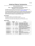
March 3, 2003
GFK-1085P
IMPORTANT PRODUCT INFORMATION
READ THIS INFORMATION FIRST
Product:
Factory LAN TCP/IP Ethernet Interface Module for IC693 PLC
IC693CMM321-GH with Firmware Release 3.10
Introduction
This document contains information about this product that is not available in any other publication; therefore, we
suggest you read it, then save it with your other PLC documentation.
General Description
This release consists of a firmware and hardware update for the IC693CMM321 Ethernet Interface Module. The
hardware update addresses a condition in some IC693CMM321-FG modules that can cause them to stop Ethernet
transmission for a period of time and then return to normal operation. Any IC693CMM321-FG module that exhibits
this behavior should be returned for update (the hardware is not field-updateable).
Firmware Release 3.10 adds MODBUS®/TCP Master and Slave functionality to CMM321 modules with catalog
numbers IC693CMM321-Fx. Firmware releases numbered 3.00 and greater apply only to revision Fx modules or later.
This firmware cannot be loaded into a IC693CMM321-Ax, -Bx, -Cx, -Dx, or –Ex. Users of the IC693CMM321-EF
and earlier modules can update by replacing their older Ethernet Interface module with an IC693CMM321-Fx or –Gx
module.
This module provides network communications using the SRTP (Service Request Transfer Protocol) over standard
TCP/IP (Transmission Control Protocol / Internet Protocol) on an Ethernet Local Area Network (LAN). The Ethernet
Interface supports communication between IC693 PLCs, IC697 PLCs, and/or IC200 PLCs equipped with TCP/IP
Ethernet Interfaces. It can communicate with the various Windows-based PLC software products and the TCP/IP
version of the DOS-based software.
Hardware Identification for IC693CMM321-GH
EM3A2-44A751166-G01 R02
Software Identification for IC693CMM321-GH
•
Software Loader: Version 3.00 (not updated in this release)
•
TCP/IP: Version 3.10
Replaces Module Versions:
IC693CMM321- FG
Firmware Field Update Kit
44A751570-G01
Note that this hardware requires the use of a Station Manager cable (IC693CBL316) to update firmware.
Hardware Compatibility
EM3A2-44A751166-G01 R00 or later versions
® MODBUS is a registered trademark of Schneider Automation, Inc.
2
Important Product Information
GFK-1085P
Functional Compatibility
Release 3.10 of the IC693CMM321 is compatible with these products:
•
IC693 PLC CPU firmware version 6.50 or later; restricted operation with CPU firmware 5.03 (6.03 for Model 351
CPU). See the section “Additional Restrictions With CPU Firmware Earlier Than Version 6.50.”
•
PLC Logic Developer version 2.11 or later.
•
VersaPro version 1.01 or later. Version 2.02 or later is required to store hardware configurations that contain
module initialization files larger than 32,768 bytes.
•
Windows®-based programming software, version 2.01 or later.
•
The MS-DOS -based programming software IC693 version 6.01 or later.
•
The MS-DOS-based programming software IC693 TCP/IP Ethernet version 7.01 or later.
Documentation
TCP/IP Ethernet Communications User’s Manual, version B
TCP/IP Ethernet Communications Station Manager Manual, version G
Version Identification
There are currently two different designs of IC693CMM321 modules. See the previous Important Product Information
for IC693CMM321-FG for feature comparison of the two module types.
Version*
Description
IC693CMM31-EF and earlier versions
AAUI-only type
IC693CMM321-FG and later versions
10Base-T type
* The module’s version is indicated by the two letters at the end of the product catalog number. For
example, in the catalog number IC693CMM321-AA, the version is indicated by AA.
MS-DOS, Windows, and Microsoft are registered trademarks of Microsoft, Incorporated.
Important Product Information
3
GFK-1085P
Special Operating Notes
This Firmware Release Is Incompatible With Version IC693CMM321-EF or Older Hardware
You should not attempt to use this firmware with older versions of this module. If this firmware version were
to be loaded to an IC693CMM321-EF or older version of this module, the module will not function as
expected, and the following symptoms will be observed:
1.
The interface is unable to go online.
2.
The STAT and SER LEDs blink alternately at a ½-second rate.
3.
The LAN Interface OK and LAN OK bits in the LAN Interface Status Word remain off.
4.
A PLC fault with text "LAN system-software fault; resuming" occurs.
5.
A System log event (Event 2, entry 2 = 0401H) occurs in the Station Manager event log.
6.
The following “incompatible hardware” message is printed to the Station Manager display from the
NODE and STAT L commands:
This firmware version requires IC693CMM321-F or later hardware. Your hardware
version is incompatible, and the network interface is unable to go online. To recover,
please use the firmware loader to reload firmware version 2.20. It is available from the
PLC Technical Support web page. See the TCP/IP Ethernet Communications User's
Manual for details.
To restore correct operation, update the module firmware to version 2.20. If you do not have the version 2.20
field update kit, part number 44A737842-G05, download the file cmm321-r220.zip from the PLC Technical
Support web page, unzip the file, and then follow the instructions in cmm321update.doc (included in the ZIP
file).
System Requirements
This version of Ethernet Interface firmware requires IC693 CPU firmware version 6.50 or later for full
operation. Restricted operation is available with CPU firmware version 5.03 or later (6.03 for the Model 351
CPU). However, Ethernet Interface users are strongly urged to update their CPU firmware. See the section
“Additional Restrictions With CPU Firmware Earlier Than Version 6.50.”
Connecting to PLC programming software via Ethernet requires both IC693 CPU version 6.50 (or later
version) and Ethernet Interface version 1.10 or higher.
Power Supply Requirements
The IC693CMM321 Ethernet Interface module (all versions/styles) will work with any IC693 power supply
with the exception that, if used with the IC693PWR321 power supply, you must use Revision K or later of this
power supply.
Power consumption of the Ethernet Interface module is 700mA @ +5VDC, plus power required by the
optional AAUI transceiver.
This version of IC693CMM321 hardware does not require an AAUI transceiver for operation on 10Base-T
networks. If an AAUI transceiver is used (for example, on an optical fiber Ethernet network), be sure to
include the +5VDC power required by the transceiver (typically 50 to 350mA) when calculating the total
power consumption of the PLC rack. Consult the transceiver documentation to obtain its power requirements.
Configuration Through Serial Port Required Before Using Ethernet Communications
The Ethernet Interface cannot operate on the network until a valid IP address is configured. The necessary
Ethernet addressing information must be configured prior to actual network operation. Two methods are
available:
1.
Perform the initial configuration using a PLC Programmer through the PLC CPU serial port.
2.
Connect a serial terminal to the Station Manager port (port 1) of the Ethernet Interface module. Then use
the CHSOSW command to enter a temporary IP address. The interface can then be reached by a PLC
programmer via Ethernet. See TCP/IP Ethernet Communications for the PLC Station Manager Manual
for details.
4
Important Product Information
GFK-1085P
Proper IP Addressing is Always Essential
The Ethernet Interface must be configured with the correct IP Address for proper operation in a TCP/IP
Ethernet network. Use of incorrect IP addresses can disrupt network operation. Refer to TCP/IP Ethernet
Communications User’s Manual for important information on IP addressing.
AAUI Cable Attachment
Power to the PLC must be turned off whenever the transceiver (AAUI) cable is connected or disconnected at
the Ethernet Interface or at the transceiver. Sudden changes in power supply loading caused by connecting or
disconnecting the transceiver with power on may result in unexpected operation of the Ethernet Interface, PLC
CPU or other modules.
Connecting the transceiver with power on may also blow the protective fuse. A blown fuse cannot be replaced
in the field; the Ethernet Interface must be returned for repair.
SQE Enable
If you use an external AAUI transceiver, the Ethernet Interface requires the SQE test signal to be enabled on
the transceiver. Make sure your transceiver has SQE enabled.
No HHP Support
The Hand Held Programmer (IC693PRG300) may not be used to configure the Ethernet Interface. Do not
attempt to configure the Ethernet Interface or to read its configuration with the HHP. Such attempts may
result in erroneous Loss-of-Module faults in the PLC Fault Table or other unexpected behavior.
Serial Load/Store of Register Table Causes Ethernet Programmers to Lose Communication
A load or store of the PLC Register (%R) table by a PLC Programmer connected through the CPU serial port
can cause Ethernet applications that use the PLC programmer communication window to lose communication.
This condition occurs when the load/store operation requires more than 10 seconds to complete. For example,
transferring the %R table of a CPU341 or CPU351 at 19,200 baud or less will cause the timeout. The Ethernet
Interface posts two or more PLC faults with the text “LAN system-software fault; resuming”, and fault-specific
data starting with 080008 and/or 080042. In addition, faults with text “Bad remote application request;
discarded request” (1B0021) and “Local request to send rejected; discarded request” (110005) may occur. The
STAT LED on the Ethernet Interface goes out.
IC693 MS-DOS TCP/IP Software Briefly Loses Communication When Configuration Cleared or Stored
Clearing or storing the PLC configuration causes the MS-DOS Ethernet programming software to display a
flashing “NO COMMUNICATIONS” message for one or two seconds. PLC faults similar to those listed
under “Serial Load/Store of Register Table Causes Ethernet Programmers to Lose Communication” above
occur; the STAT LED on the Ethernet Interface goes out. In some cases, a ten second delay occurs before loss
of communication is detected.
When the PLC configuration is stored from the MS-DOS Ethernet programming software, the communications
loss occurs immediately after successful completion of the store. Attempts to store configuration plus logic
and/or reference tables in one operation can fail. However, storing configuration separately from logic or
reference tables will always succeed.
See the “Restrictions and Significant Open Problems” section for a description of operational behavior when
configuration is cleared or stored using VersaPro.
Clearing Slot Configuration Closes TCP Connections
When the PLC CPU contains version 6.50 or later firmware, clearing the slot configuration of the Ethernet
Interface causes the interface to close all of its TCP connections immediately. The Ethernet Interface slot
configuration is cleared when a PLC Programmer connected via Ethernet clears the PLC configuration, or
stores a new configuration with an empty slot or different module type at the location where the interface is
installed. PLC faults similar to those listed under “Serial Load/Store of Register Table Causes Ethernet
Programmers to Lose Communication” above occur; the STAT LED on the Ethernet Interface goes out.
Applications that use the Ethernet Interface’s SRTP server, such as Host Communications Toolkit client
applications, must be aware that the connection has closed and take action to establish a new connection.
Important Product Information
5
GFK-1085P
Extra Channels Data Transfer Entering STOP/IOSCAN Mode
Use caution when configuring the PLC CPU to scan I/O in STOP mode. There is a small time delay between a
RUN to STOP/IOSCAN mode transition in the PLC CPU and the time when the Ethernet Interface deactivates
repeating channels. The length of this delay varies with the PLC hardware configuration and the application
program. In some cases, the time delay will be long enough that one data transfer by a repeating channel will
occur after the CPU mode transition.
After a RUN to STOP/NO IO mode transition, the Ethernet Interface aborts repeating channels immediately.
RUN Mode Program Store
A store of a folder containing large (greater than 14kb) program blocks using a PLC Programmer via Ethernet
may fail and result in momentary loss of communication. This condition has been observed only when
attempting to store a large program to a PLC which is in RUN mode, and which is configured to use a limited
communication window. These conditions cause the store operation to take the maximum possible period to
complete. The failure may occur if this period exceeds 10 seconds for an individual program block. If this
problem does occur, one of the following options may be used to complete the store operation successfully:
1.
Change the PLC configuration to use Run-to-Completion mode instead of a Limited Communication
Window for the store operation.
2.
Change the PLC from RUN to STOP mode to complete the store.
3.
Structure the folder being stored to eliminate large program blocks or subroutine blocks. This will
minimize the chance that any single block will take longer than the maximum 10-second period allowed
for storage of that block.
6
Important Product Information
GFK-1085P
New Features and Functionality of this Release (3.10)
Modbus/TCP Master
This firmware release adds the ability for the user application program to issue COMMREQs to initiate
Modbus/TCP read and write operations. Details of the Modbus/TCP Channel services available can be found
in Chapter 4 of the TCP/IP Ethernet Communications User’s Manual.
Modbus/TCP Slave
With this firmware release, the IC693 will respond to incoming Modbus/TCP read and write operations.
Details of the memory address mapping can be found in Appendix E of the TCP/IP Ethernet Communications
User’s Manual.
Problems Fixed In this Release (-Gx hardware)
Ethernet module may occasionally cease transmission for several seconds
The IC693CMM321-FG module may stop transmitting Ethernet traffic, and then spontaneously resume
transmission a few seconds later. Depending on the nature of the traffic, the user may observe SRTP Channel
timeouts, timeouts to programmers and HMIs, and no response to incoming PINGs. The module’s exception
log may contain c/10b and 11/5 entries. Note:
•
Revisions earlier than –FG are not subject to this behavior
•
Any –FG modules that exhibit this behavior should be returned to GE Fanuc for update to –Gx
version.
Important Product Information
GFK-1085P
Restrictions and Open Problems
•
The Ethernet Interface sometimes generates multiple exception log events and PLC Fault Table entries
when a single error condition occurs. Under repetitive error conditions, the exception log and/or PLC
Fault Table can be completely filled with repetitive error messages.
•
Initialization errors that generate any of the following exception log events should also restart the
Ethernet Interface into Maintenance state: event 1b, entry 2 = 0003h; event 1c, entry 2 = 25h, or event
1c, entry 2 = 26h. The Ethernet Interface does not restart in these conditions.
•
Use of the same IP Address by this Ethernet Interface and by another device on the same network
results in the PLC Fault Table message “Bad remote application request; discarded request.” This
condition should be identified more precisely.
•
When the client or server PLC scan time exceeds 100 ms, channels may fail with error codes 2411,
0B11, 9B90, 3F11, or 9590. The error codes may be viewed by doing a Stat H command.
•
While a local Station Manager “TRACE LZ” troubleshooting command is in effect at an Ethernet
Interface, do not issue Station Manager “REM <node> TEST” commands to it from a remote Interface.
Doing so can cause errant behavior, including Interface lockup and loss-of-module in the PLC fault
table.
•
After performing a firmware update to an Ethernet Interface in which one or more Advanced User
Parameters have been set to non-default values, the PLC Fault Table does not contain the message it
should ( “LAN IF can’t init-check parms; running soft Sw Utl”); rather, no fault table entry appears.
There is no indication in the fault table that the Ethernet Interface has entered Maintenance state to
permit resetting of the user parameter(s). The Ethernet Interface does generate an entry in its exception
log.
•
The TCP tallies CurEstab and EstabRes do not always report the correct value.
•
An Information Report channel may remain in the AWAIT_DRSP or AWAIT_CRSP state indefinitely
if the remote host fails to send a response.
•
When using VersaPro via Ethernet through this Ethernet Interface, a Clear operation that does not
include clear of Software Configuration causes VersaPro to “crash”. This behavior is not observed
using the other Ethernet programmers or if VersaPro is connected to the PLC via the Ethernet Interface
within an IC693CPU364. Rebooting the PC is often required to re-establish communication with the
PLC.
•
.
7
8
Important Product Information
GFK-1085P
Additional Restrictions with CPU Firmware Earlier Than Version 6.50
Ethernet Programming Not Supported
Using a PLC programmer via Ethernet requires both IC693 CPU version 6.5 and Ethernet Interface version
1.10. The programmer may appear to connect with a PLC using older CPU firmware, but essential functions
will not work correctly.
CAUTION
Do not attempt to use an Ethernet programmer with CPU
firmware earlier than version 6.50. Unpredictable operation of
both the PLC CPU and MS-DOS programming software will
occur.
Single Incoming Network Connection to CPU
PLC CPU firmware versions earlier than 6.50 can support only one incoming network connection through the
Ethernet Interface at a time. The Ethernet Interface consequently supports only one incoming connection at a
time when used with this CPU firmware.
No Operation in Expansion or Remote Rack
With CPU firmware versions earlier than 6.50, locate the Ethernet Interface in the main PLC rack only (Rack
0, which contains the CPU). The Ethernet Interface is not supported by this CPU firmware in an expansion or
remote PLC rack.
Incoming Network Connection May Be Refused After Restart
After any restart, including power up, the Ethernet Interface is unable to accept incoming network connections
for approximately 2.5 seconds after the LAN Interface OK bit of the LAN Interface Status Word is set. This
occurs only with CPU firmware earlier than version 6.50.
Unconfigured Ethernet Interface Inoperative for Two Minutes After Restart
With CPU firmware versions earlier than 6.50, an unconfigured Ethernet Interface waits for two minutes after
each restart to receive valid configuration data from the PLC CPU. The interface slowly flashes its Module
OK LED and is not operational during this time. This behavior occurs when a new interface is powered on for
the first time. It also occurs when a PLC Programmer user clears the PLC configuration, or stores a new
configuration with an empty slot or different module type at the location where the Ethernet Interface is
installed.
User Manual Notes (Version B)
These changes will be made in Version C of the manual, when available.
Chapter 4, Table “Minor Error Codes for Major Error Codes 90H (Client API Error)”
The description of Error Status 8890H should read “Invalid channel number or channel is in an inactive state
(for example, the remote device has been turned off or disconnected, or the ‘killms’ Station Manager command
was used at the remote device to stop the channel)”.
Chapter 6, “TCP Port Numbers” (new section, follows “MAC Addresses” section)
The TCP port number on which the SRTP server listens for incoming messages is 18245 (decimal).
The TCP port number on which the Modbus/TCP server listens for incoming messages is 502 (decimal).
Appendix E, Table E-1 “Modbus Register/IC693CMM321 Reference Table Translation”
Note that current IC693 PLCs support 2048 bits of %I and %Q. The mapping table shows 4096 bits, for
potential future growth. Do not attempt to read %I or %Q bits beyond 2048.