1
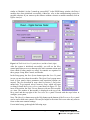
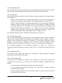
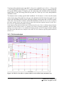
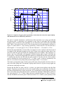
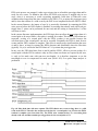
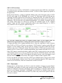
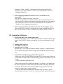
GDT (GATE dead time) The dead time from GATE or VETO/GFLT is counted separately from SFDT for each channel. As mentioned above and further described in section 7.4, the use of these signals may depend on the application. In the current firmware, a rising (or optionally falling) edge at the Gate input creates a GATE PULSE with length GATE WINDOW (see section 7.4). Both this GATE PULSE and the (optionally inverted) signal on the VETO input are combined into GDT_ON. While GDT_ON is high, GDT is incremented every clock cycle and thus counts the time pulses can be rejected from acquisition. (The rejection has to be enabled independently). It is possible to instead count the time during which pulses are allowed by inverting the combined signal. In the “standard statistics” mode, the GDT counter is additionally subject to the channel being live, i.e. GDT is only counted if a run is in progress, signal in range, etc. Fig. 6.12 GDT counting logic shown for standard statistics mode. In Gate statistics mode, the channel LIVE signal is ignored for counting GDT and in turn LIVE is subject to GDT_ON. To support the third case of gating mentioned above, where the acquisition is only of interest when GATE or VETO are off, there is an alternate “GATE statistics” mode to count GDT and livetimes. In Gate statistics mode, all time and rate counters except RUN TIME and TOTAL TIME are only active if GDT_ON is high. This means GATE or VETO must be present for the channel to be live. In turn, GDT is counted independently from whether the module is live or not. If the VETO input is unused but defaults to high so that GDT is equal to the live time, invert the VETO polarity in the CHANNEL REGISTER Panel to only count the GATE PULSE time. The VETO input can be used instead of the GATE input for the gating circuitry, and if this option is used only the GATE PULSE derived from the VETO input is counted, not the original VETO. For the case that the Veto input is used for a GFLT-type validation pulse, it may be more useful to work with the number of pulses issued. They can be counted by using the VETO input as the source for GATE PULSEs, which are counted in the variable GCOUNT. 6.6.3 Count rates Besides the live and dead times, the Pixie-4 counts the numbers of triggers in each channel, FASTPEAKS, the number of valid events with one or more channels, NUMEVENTS, and the number of valid pulses stored for each channel, NOUT. In addition, it counts the number of gate pulses for each channel, GCOUNT. FASTPEAKS and GCOUNT are inhibited when the live time is not counted. NUMEVENTS and NOUT by nature only count events captured when the live time is counted. 53 PIXIE-4 User’s Manual V2.54 XIA 2013. All rights reserved.