1
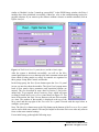
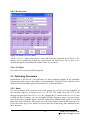
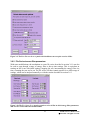
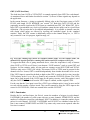
7.2.5 External Triggers External triggers usually do not have the correct format and fast trigger vs event trigger timing required by the Pixie-4 trigger logic. The Pixie-4 therefore includes specific logic to turn an external signal into distributed triggers. External signals (3.3V TTL standard) can be connected to the Pixie-4 front panel input labeled “DSP-OUT”. The DSP variable XETDELAY (Control field Validation delay … in the CHASSIS SETUP panel controls generation of fast and event triggers. If the value is zero, no triggers are generated. If the value is nonzero, a fast trigger is issued to the backplane immediately after detection of a rising edge on the front panel, and an event trigger is issued the specified delay thereafter. As the triggers are sent to the backplane, the external triggers appear as if an additional module with a pileup inspection time (energy filter rise time plus flat top) equal to XETDELAY had seen a pulse. Sharing triggers over the backplane must be enabled even for the module connecting to the external signal. 7.3 Run Synchronization It is possible to make all Pixie-4 modules in a system start and stop runs at the same time by using a wired-OR SYNC line on the PXI backplane. In all modules the variable SYNCHWAIT has to be set to 1. If the run synchronization is not used SYNCHWAIT must be set to 0. The variable is set by checking the corresponding checkbox in the Run Control tab of the Pixie Viewer. The run synchronization works as follows. When the host computer requests a run start, the Pixie-4’s DSP will first execute a run initialization sequence (clearing memory etc). At the beginning of the run initialization the DSP causes the SYNC line to be driven low. At the end of the initialization, the DSP enters a waiting loop, and allows the SYNC line to be pulled high by pullup resistors. As long as at least one of all modules is still in the initialization, the SYNC line will be low. When all modules are done with the initialization and waiting loop, the SYNC line will go high. The low->high transition will signal the DSP to break out of the loop and begin taking data. If the timers in all modules are to be synchronized at this point, set the variable INSYNCH to 0 by checking the corresponding checkbox in the Run tab of the Pixie Viewer. This instructs the DSP to reset all timers to zero when coming out of the waiting loop. From then on they will remain in synch if the system is operated from one master clock. Whenever a module encounters an end-of-run condition and stops the run it will also drive the SYNC line low. This will be detected in all other modules, and in turn stop the data acquisition. Note that if the run synchronization is not operating properly and there was a run start request with SYNCHWAIT=1, the DSP will be caught in an infinite loop. This can be recognized by reading the variables INSYNCH and SYNCHWAIT. If after the run start request the DSP continues to show INSYNCH=0 and SYNCHWAIT=1, it is stuck in the loop waiting for an OK to begin the run. Besides rebooting, there is a software way to force the DSP to exit from that loop and to lead it back to regular operation. See the Programmer’s Manual for details. 60 PIXIE-4 User’s Manual V2.54 XIA 2013. All rights reserved.