1
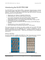
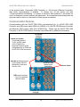
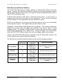
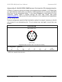
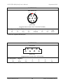
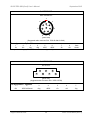
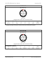
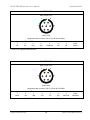
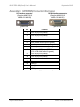
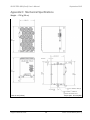
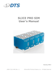
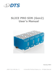
SLICE PRO SIM (Gen3) User’s Manual September 2015 13018-7A339-MAN (Rev. 9) © Diversified Technical Systems, Inc. - All Rights Reserved SLICE PRO SIM (Gen3) User’s Manual September 2015 Table of Contents DTS Support ....................................................................................................................... 4 Introducing the SLICE PRO SIM........................................................................................ 5 Sensor Interface ................................................................................................................. 5 Supported Sensor Types ................................................................................................. 6 Input Range ..................................................................................................................... 6 Excitation Sources ........................................................................................................... 6 Bridge Completion ........................................................................................................... 6 Hardware Filters............................................................................................................... 7 Offset Compensation ....................................................................................................... 7 Electronic Identification (EID) ........................................................................................... 7 Shunt Emulation............................................................................................................... 7 Sampling Rates .................................................................................................................. 8 Data Memory Size............................................................................................................... 8 UP/DOWN Interface Connectors ....................................................................................... 8 LEDs .................................................................................................................................... 9 Basic Care and Handling ................................................................................................. 10 Shock Rating.................................................................................................................. 10 Mounting Considerations ........................................................................................... 10 Thermal Considerations ................................................................................................. 10 Power Management.......................................................................................................... 11 Power Consumption ....................................................................................................... 11 Internal Battery............................................................................................................... 11 Power-up and Power-down Procedures ........................................................................ 11 Communication Features ................................................................................................ 12 Data Collection Concepts ................................................................................................ 13 Data Collection Modes ................................................................................................... 13 Circular Buffer Mode .................................................................................................. 13 Recorder Mode .......................................................................................................... 13 Hybrid Recorder Mode............................................................................................... 13 Continuous Recorder Mode ....................................................................................... 13 support.dtsweb.com ii 13018-7A339-MAN (Rev. 9) SLICE PRO SIM (Gen3) User’s Manual September 2015 Start Record and Event Initiation ................................................................................... 14 Appendix A: SLICE PRO SIM Sensor Connector Pin Assignments............................. 15 Appendix B: UP/DOWN Connector Information ........................................................... 20 Appendix C: Mechanical Specifications........................................................................ 21 Appendix D: How to Calculate Data Storage Duration................................................. 23 Circular Buffer Limitations .............................................................................................. 23 support.dtsweb.com iii 13018-7A339-MAN (Rev. 9) SLICE PRO SIM (Gen3) User’s Manual September 2015 DTS Support SLICE PRO systems are designed to be reliable and simple to operate. Should you need assistance, DTS has support engineers worldwide with extensive product knowledge and crash test experience to help via telephone, e-mail or on-site visits. The best way to contact a DTS support engineer is to submit a request through the DTS Help Center web portal (support.dtsweb.com). You must be registered (support.dtsweb.com/registration) to submit a request (https://support.dtsweb.com/hc/enus/requests/new). Registration also enables access to additional self-help resources and non-public support information. This manual supports the following products: 13009-7A102: SLICE PRO SIM (9 ch); automotive, 120 ohm br (Option A5) 13009-7A121: SLICE PRO SIM (9 ch); automotive, 120 ohm br (Option 21) 13009-7A304: SLICE PRO SIM (9 ch); automotive, 350 ohm br (Option E) 13009-7A339: SLICE PRO SIM (9 ch); automotive, 350 ohm br (Option 39) 13009-7A342: SLICE PRO SIM (9 ch); automotive, 350 ohm br (Option 42) 13009-7H140: SLICE PRO SIM (9 ch); high bandwidth, 120 ohm br (Option 40) 13009-7H346: SLICE PRO SIM (9 ch); high bandwidth, 350 ohm br (Option 46) 13009-7M121: SLICE PRO SIM (9 ch); max bandwidth, 120 ohm br (Option 21) 13009-7M339: SLICE PRO SIM (9 ch); max bandwidth, 350 ohm br (Option 39) 13009-7M347: SLICE PRO SIM (9 ch); max bandwidth, 350 ohm br (Option 47) 13018-7A102: SLICE PRO SIM (18 ch); automotive, 120 ohm br (Option A5) 13018-7A121: SLICE PRO SIM (18 ch); automotive, 120 ohm br (Option 21) 13018-7A139: SLICE PRO SIM (18 ch); automotive, 120 ohm br (Option 39) 13018-7A302: SLICE PRO SIM (18 ch); automotive, 350 ohm br (Option A5) 13018-7A321: SLICE PRO SIM (18 ch); automotive, 350 ohm br (Option 21) 13018-7A339: SLICE PRO SIM (18 ch); automotive, 350 ohm br (Option 39) 13018-7A342: SLICE PRO SIM (18 ch); automotive, 350 ohm br (Option 42) 13018-7A346: SLICE PRO SIM (18 ch); automotive, 350 ohm br (Option 46) 13018-7H121: SLICE PRO SIM (18 ch); high bandwidth, 120 ohm br (Option 21) 13018-7H321: SLICE PRO SIM (18 ch); high bandwidth, 350 ohm br (Option 21) 13018-7H339: SLICE PRO SIM (18 ch); high bandwidth, 350 ohm br (Option 39) 13018-7H345: SLICE PRO SIM (18 ch); high bandwidth, 350 ohm br (Option 45) 13018-7H346: SLICE PRO SIM (18 ch); high bandwidth, 350 ohm br (Option 46) 13018-7M121: SLICE PRO SIM (18 ch); max bandwidth, 120 ohm br (Option 21) 13018-7M139: SLICE PRO SIM (18 ch); max bandwidth, 120 ohm br (Option 39) 13018-7M339: SLICE PRO SIM (18 ch); max bandwidth, 350 ohm br (Option 39) support.dtsweb.com 4 13018-7A339-MAN (Rev. 9) SLICE PRO SIM (Gen3) User’s Manual September 2015 Introducing the SLICE PRO SIM The SLICE PRO Sensor Input Module (SIM) is a high-speed, high-performance, industrial data acquisition system. The system is configurable and is supplied with either 9- or 18channels. The SLICE PRO SIM supports many sensor types and sensitivities, interfacing with common and not-so-common sensors. Sample rates up to 1 Msps on 9 channels simultaneously. Shock hardened to 100 g for dynamic testing environments. 9 or 18 sensor input channels, each with isolated excitation, high impedance differential input amplifier, and automatic sensor identification circuits. Internal battery with up to 1 hour capacity functions as primary or back-up power. LED indicators for power and system status. Easy communications via the SLICE PRO USB Controller or SLICE PRO Ethernet Controller. Chainable with up to three other SLICE PRO modules. Each channel supports conventional bridge sensors or IEPE sensors. This manual discusses the features and options available with the SLICE PRO SIM. Connector information and pin assignments can be found in Appendices A and B. Mechanical specifications are included in Appendix C. Appendix D provides information on how to calculate data storage duration. Please see your packing list for your hardware’s specifications. Sensor Interface The SLICE PRO SIM is available with LEMO 1B or Tajimi 7-pin sensor input connectors. See Appendix A for pin assignments and detailed sensor connection information. (18-channel SLICE PRO SIMs are shown; 9-channel units are also available.) support.dtsweb.com 5 13018-7A339-MAN (Rev. 9) SLICE PRO SIM (Gen3) User’s Manual September 2015 Supported Sensor Types The SLICE PRO SIM supplies 2, 5, 7.5 and 10 V excitation up to 40 mA and supports many types of sensors including accelerometers, load cells and pressure sensors. The following general sensor types are supported: Full-bridge (4-wire), half-bridge (3-wire), quarter-bridge (e.g., 2- or 3-wire strain gage), resistive and piezo-resistive types. Voltage input range: ±2.5 V; up to 800 V with available range expander cable. Conditioned sensors with 2.5 V centered signal output. IEPE sensors, including accelerometers, microphones and many others. If you have additional questions regarding what sensors are supported, please contact DTS and provide the sensor manufacturer and model number, if available. Input Range The nominal sensor input range is ±2.5 V at a gain of 1. At higher gains, the maximum range decreases correspondingly. For example, at a gain of 10, the input range is ±240 mV. (The software will automatically calculate the gain based on the user-specified input range and other sensor parameters.) The nominal input range for an IEPE sensor is 0-24 V (±12 V) at unity gain. As with bridges, at higher gains, the input range decreases accordingly. For example, when the SLICE PRO SIM applies a gain of 4, the input range will be 4 times smaller, or ±3 mV. Excitation Sources The excitation source for each channel is individually controlled and isolated. Excitation sources are not turned on until the software initializes the system during diagnostics. The bridge excitation can be set at 2.0, 5.0, 7.5, 10.0 V or off. The constant current IEPE excitation is fixed at 4.0 mA. Bridge Completion Half-bridge and 3/4-bridge completion for any channel may be selected via software. Halfbridge transducers should be connected to ±Ex and -Sig. The value of half-bridge completion resistors is 3,000 ohms (±0.1%). Quarter-bridge transducers should be connected to +Ex and –Sig. There are two options available: 350 ohm (±0.1%) or 120 ohm (±0.1%). Please see your packing list for your hardware’s specifications. support.dtsweb.com 6 13018-7A339-MAN (Rev. 9) SLICE PRO SIM (Gen3) User’s Manual September 2015 Hardware Filters There are three hardware filter combinations available. (Your packing list identifies the specifications of your unit.) Each option includes: A fixed, 8-pole Butterworth anti-aliasing filter with one fixed -3 dB knee point, and A software-controlled, variable 5-pole Butterworth filter. Bandwidth Option 8-pole Filter (fixed) Automotive (standard) 4 kHz (for rates ≥20 ksps) 100 kHz (for rates of 500 ksps or 1 Msps) 200 kHz (for rates of 500 ksps or 1 Msps) High Maximum 5-pole Filter (adjustable up to 45 kHz) for rates <20 ksps for rates <500 ksps for rates <500 ksps The 5-pole filter is used together with the 8-pole filter at lower sampling rates. The software will automatically choose the best filter setting for a given sampling rate. The relationship between sampling rate and anti-alias filter frequency is defined in the software configuration files. Please see the software manual for additional information. Offset Compensation Each channel can compensate for a sensor offset of up to 200% of the full-range output of a sensor. The sensor offset is measured and the hardware compensation is adjusted during the diagnostic check. Please see the software manual for additional information. Electronic Identification (EID) Each measurement channel supports communication with silicon serial number devices manufactured by Dallas Semiconductor/Maxim Integrated Products for both bridge and IEPE sensors. When an ID chip is connected to the proper pins on the sensor connector, the software can automatically read these devices and correlate the serial number to channel set-up information stored in the sensor database. (Note that sensor ID for IEPE is typically integrated into the sensor using the existing two-wire interface and do not require a separate pin.) Shunt Emulation SLICE PRO SIM channels contain a shunt emulation circuit, effectively eliminating the need for conventional shunt resistors to perform shunt checks. When “Emulation” is chosen as the shunt calibration method, the software injects a precisely-calculated current into the sensor to create an expected deflection of the sensor's output. Settings are automatically calculated by the software to simulate 70-80% of the full-scale of the analog-to-digital converter. Please see the software manual for additional information. support.dtsweb.com 7 13018-7A339-MAN (Rev. 9) SLICE PRO SIM (Gen3) User’s Manual September 2015 Sampling Rates The SLICE PRO SIM has user-selectable sampling rates from 100 sps to 1 Msps. The maximum sampling rate for 9 channels is 1 Msps; the maximum sampling rate for 18 channels is 500 ksps. Only 9 channels (channels 1-9 specifically) are available for any sampling rate >500 ksps. For information on how to calculate data storage duration, please see Appendix D. Data Memory Size With 15 GB of flash memory available for data storage, the SLICE PRO SIM can record ~14 minutes of data at the maximum sampling rate (9 channels at 1 Msps or 18 channels at 500 ksps). Since the recording capacity is very large, it is generally best to limit sampling rates and event durations to the minimum necessary to avoid large and cumbersome data files. Large files take longer to download and may also be time-consuming to post-process or difficult to share. Use of the Region of Interest (ROI) download can save a great deal of time if implemented properly. For information on how to calculate data storage duration, please see Appendix D. UP/DOWN Interface Connectors The UP interface connector allows the user to interface to either 1) a SLICE PRO Controller, or 2) another SLICE PRO module. The DOWN interface connector allows the user to interface to another SLICE PRO module. Please see Appendix B for pin assignments. support.dtsweb.com 8 13018-7A339-MAN (Rev. 9) SLICE PRO SIM (Gen3) User’s Manual September 2015 LEDs The SLICE PRO SIM has two LEDs. At system power up, the red-green-blue LED initialization sequence is performed by the status LED followed by the power LED. LED behavior is summarized in the tables below. Recorder Mode Circular Buffer Mode Armed and waiting for Start Record signal to begin data collection Start Record signal received and recording data; waiting for Event signal (optional) Event signal received (optional) –or– fault Event signal received + data collection completed (no USB) Armed and recording data; waiting for Event signal Event signal received –or– fault Event signal received + data collection completed (no USB) Fault received + data collection completed (no USB) Fault received + data collection completed (no USB) Data collection completed; PC downloading data Data collection completed; PC downloading data Condition Charging (system off and connected to external power) Unit is charging (power OK) Unit fully charged System on; not armed ... Power up Power OK; no USB Power OK; USB connected Power fault (out of range) Communicating with host support.dtsweb.com 9 13018-7A339-MAN (Rev. 9) SLICE PRO SIM (Gen3) User’s Manual September 2015 Basic Care and Handling The SLICE PRO systems are precision devices designed to operate reliably in dynamic testing environments. Though resistant to many environmental conditions, care should be taken not to subject the unit to harsh chemicals, submerge it in water, or drop it onto any hard surface. WARNING: Electronic equipment dropped from desk height onto a solid floor may experience as much as 10,000 g. Under these conditions, damage to the exterior and/or interior of the unit is likely. The SLICE PRO SIM is supplied with calibration data from the factory. DTS recommends annual recalibration to ensure that the unit is performing within factory specifications. The SLICE PRO SIM is not user-serviceable and should be returned to the factory for service or repair. When not in use or if shipping is required, we suggest that you always place the unit in the padded carrying case originally provided with your unit. Shock Rating The SLICE PRO SIM is rated for 100 g, 12 ms half-sine duration, in all axes. Mounting Considerations The unit should be securely bolted to the test article or dynamic testing device to provide the best shock protection. Mounting methods and hardware selection should be carefully calculated to withstand expected shock loading and facilitate proper grounding. Check bolt tightness periodically to ensure that 1) the unit is securely fastened to the baseplate, and 2) the baseplate is securely fastened to the testing platform. (See Appendix C for the unit’s mechanical specifications.) Thermal Considerations The SLICE PRO systems are low power devices with negligible self-heating and it is unlikely that self-heating will be an issue in real-world testing. Should you have any questions about using SLICE PRO in your environment, please contact DTS. support.dtsweb.com 10 13018-7A339-MAN (Rev. 9) SLICE PRO SIM (Gen3) User’s Manual September 2015 Power Management A good power source is of paramount importance. SLICE PRO SIMs should be powered from a SLICE PRO Controller. (One Controller can support up to 4 SLICE PRO modules.) Be sure to consider any power drop due to cable length. Input Voltage, System OFF/ON Power Consumption, System OFF* Power Consumption, System ON** 11.5-16 VDC; 15 VDC nominal 7.5 W; 500 mA per module*** 15 W; 1 A per module*** * charging all internal batteries ** fully armed + charging all internal batteries *** Controllers are considered modules for the purposes of power calculations. Power Consumption Power off: When connected to sufficient external power, the SLICE PRO SIM will draw up to 500 mA for charging the internal battery. Power on: When the SIM is initially powered, all sensor excitation sources, calibration circuitry, signal conditioning sources, adjustable filter circuits are in a shutdown state. When the user runs a test set-up, the software automatically energizes these circuits. The current draw per module will increase from ~625 mA to as much as 1 A when the system is fully armed and powering 350 ohm bridges with 5 V excitation. During data collection: Once the system has been armed for data collection, all circuits remain in a full power state until data collection is finished. After the data collection routine has completed, the SIM de-energizes the signal conditioning, excitation and filter circuits to minimize power consumption. Internal Battery The SLICE PRO SIM contains an internal 7.4 V (nominal) lithium battery that operates as primary power or back-up power should primary power fail. When fully charged, battery capacity is sufficient to provide primary power and sustain full operation for 1 hour with 5 V excitation (40 minutes with 10 V excitation). It charges whenever sufficient external power is connected to the module via a SLICE PRO Controller. The maximum charge time is 34 hours from complete discharge to full capacity. The module does not need to be ON in order to charge the internal battery. Charging practices can affect the useful operational life of the battery. In addition to good charging habits, conditioning the battery may be useful—three deep-discharge/recharge cycles may help increase battery performance. The battery’s useful capacity is greatly shortened near the end of its service life and should be replaced when it has decreased to 50% of its initial capacity. The battery is not user-serviceable and should be returned to the factory for battery replacement. Power-up and Power-down Procedures The SLICE PRO SIM is powered up when the proper signal is connected at the UP interface connector. This is typically accomplished via a SLICE PRO Controller. Power-up support.dtsweb.com 11 13018-7A339-MAN (Rev. 9) SLICE PRO SIM (Gen3) User’s Manual September 2015 of the module takes 10 seconds (USB Controller) or ~90 seconds (Ethernet Controller), after which communication is enabled. To restart, turn off the system and wait ~30 seconds before reinitializing. If a system is armed for data collection, it will remain on until it is disarmed or power reserves are exhausted. An incomplete power-down/power-up cycle can result in errors, so be certain to follow proper procedures. Communication Features Communications with the SLICE PRO SIM is accomplished via 1) a SLICE PRO USB Controller and USB comm cable (USB A to USB B) or 2) a SLICE PRO Ethernet Controller and Ethernet (REC) comm cable (P/N 10700-0015x). Please see the SLICE PRO USB Controller or SLICE PRO Ethernet Controller User’s Manuals for additional information. SLICE PRO Ethernet Controller COM A and COM B - Functionally identical - To PC via REC cable (P/N 10700-0015x) - Supports Ethernet 10/100 - Compatible with all TDAS and SLICE PRO COM connectors ON/PWR pushbutton switch - Cycles power ON/OFF - Momentary; press and hold for 2 sec SLICE PRO SIM (sensor input connectors) Power Input USB communications - To PC via standard USB A-B cable SLICE PRO USB Controller SLICE PRO System Set-up support.dtsweb.com 12 13018-7A339-MAN (Rev. 9) SLICE PRO SIM (Gen3) User’s Manual September 2015 Data Collection Concepts The discussion below provides a general introduction to data collection. Please see the software manual for a detailed discussion and implementation specifics. SLICE is a standalone data logger. Once the system is armed, the PC can be disconnected if desired. After receiving a Start Record or Event signal, SLICE autonomously collects data, storing it to flash memory with no user interaction. After the test, the user reconnects the PC to download the data. There is also a real-time mode in the control software that allows the user to check channel inputs on an oscilloscope-looking screen. (This data can be logged.) Data Collection Modes SLICE supports four data collection modes: Circular Buffer, Recorder, Hybrid Recorder, and Continuous Recorder. (Note: The software cannot simultaneously display the data while the system is recording.) Circular Buffer Mode Using Circular Buffer mode, the user can program SLICE to record pre- and post-Event data. Time Zero (T=0) is marked when the Event signal is received. Due to the nature of flash memory, the system cannot be armed in Circular Buffer mode indefinitely. Please see Appendix D for information on how to calculate data storage duration when using Circular Buffer mode. Recorder Mode Data collection begins when a Start Record signal is received and continues for the time specified in the test set-up. If an Event signal is received sometime after the Start Record, this is marked as T=0. Hybrid Recorder Mode Data collection begins when a Start Record signal is received and continues until the unit receives an Event signal. The unit then records for the post-Event time specified by the user. The Event signal marks the T=0 point and all data recorded is available for download. Continuous Recorder Mode Data collection begins when a Start Record signal is received and continues until the Start Record signal is released. The unit will then re-arm for another event. The LEDs on the unit will flash blue slowly then rapidly, and then the status LED will become solid blue, indicating the unit is fully armed. The unit will continue to record new events until it records the number of events specified by the user. If an Event signal is received after the unit has re-armed, the unit will disarm and no longer attempt to re-arm. support.dtsweb.com 13 13018-7A339-MAN (Rev. 9) SLICE PRO SIM (Gen3) User’s Manual September 2015 Start Record and Event Initiation The SLICE PRO SIM supports multiple methods of initiating Start Record and Event signals. Typically, Start Record and Event are initiated via an external hardware interface that provides a discrete contact closure (CC) signal to initiate recording (Recorder mode) or mark T=0 (Circular Buffer mode). All SLICE data collection modes have a multi-event arming mode. A unit armed in a multiple-event mode will re-arm when an event completes. The unit will stop re-arming when the number of events specified by the user has been recorded. SLICE can be placed in an auto-arm mode that will cause the unit to arm automatically when the power is cycled. This available with any data collection mode. Additionally, Circular Buffer mode supports level triggering. This method continuously samples the incoming data and begins data collection if the data is above or below predefined levels. For example, it might be useful to begin data collection when a certain accelerometer experiences a force above 200 g. Using level trigger, and Circular Buffer mode, the SLICE PRO SIM can support this or any level-trigger signal on any channel. Finally, if the SLICE PRO SIM remains connected to the PC during data collection, the control software can be used to begin data collection. The table below summarizes the data collection modes and event/triggering options. Supports T=0 Start Record Circular Buffer Yes Recorder Yes Hybrid Recorder Yes Continuous Recorder Yes support.dtsweb.com T=0 methods supported Hardware (CC), software (PC) or level trigger Hardware (CC), software (PC) or level trigger Hardware (CC), software (PC) or level trigger Hardware (CC), software (PC), or level trigger 14 Data record window User-defined pre- and post- T=0 durations User-defined duration after T=0 User-defined post-Event duration User-defined duration after T=0, with recording multiple events possible 13018-7A339-MAN (Rev. 9) SLICE PRO SIM (Gen3) User’s Manual September 2015 Appendix A: SLICE PRO SIM Sensor Connector Pin Assignments A variety of connector options and sensor pin assignments are available. It is unlikely that you can determine what option you have by visual inspection as a connector may have more than one pin assignment option. If you need information on the specifics of your equipment, please submit a request through the DTS Help Center web portal (support.dtsweb.com) and provide the serial number(s) of the equipment and parameters you are asking about. Some pin assignments permit multiple termination options for a signal, however you should only connect to one termination point. Do not connect any one signal to more than one location. SLICE PRO SIM EEG.1B.307.CLL 1 6 7 2 5 3 4 (panel view) (Suggested cable connector P/N: FGG.1B.307.CLAD42*) Pin assignments: Option A502** 1 N/C 2 +ID 3 +Sig 4 +Ex 5 -Ex 6 -Sig 7 N/C Case -ID/Shield * A 6-pin connector (i.e., FGG.1B.306.CLAD42) may also be used. ** IEPE is not supported with this option. support.dtsweb.com 15 13018-7A339-MAN (Rev. 9) SLICE PRO SIM (Gen3) User’s Manual September 2015 SLICE PRO SIM EEG.1B.307.CLL 1 6 7 2 5 3 4 (panel view) (Suggested cable connector P/N: FGG.1B.307.CLAD42*) Pin assignments: Option E04** 1 +Ex 2 -Ex 3 +Sig 4 -Sig 5 -ID/Shield 6 +ID 7 N/C Case Shield * A 6-pin connector (i.e., FGG.1B.306.CLAD42) may also be used. ** IEPE is not supported with this option. SLICE PRO SIM 3RT01-R7F 6 7 2 4 5 3 1 (panel view) (Suggested cable connector P/N: 3RT01-PE7M) Pin assignments: Option 21* 1 +Ex 2 Shield 3 +Sig 4 -ID 5 -Ex 6 +ID 7 -Sig * IEPE is not supported with this option. support.dtsweb.com 16 13018-7A339-MAN (Rev. 9) SLICE PRO SIM (Gen3) User’s Manual September 2015 SLICE PRO SIM EEG.1B.308.CLL 1 7 2 8 6 3 5 4 (panel view) (Suggested cable connector P/N: FGG.1B.308.CLAD42) Pin assignments: Option 39* 1 -Ex 2 +Ex 3 -Sig 4 +Sig 5 -IEPE 6 +IEPE 7 -ID 8 +ID Case Shield * Compatible with legacy TDAS DTS standard sensors (option 01). SLICE PRO SIM 3RT01-R7F 6 7 2 4 5 3 1 (panel view) (Suggested cable connector P/N: 3RT01-PE7M) Pin assignments: Option 40 1 +Ex 2 -IEPE/-ID/Shield support.dtsweb.com 3 +Sig 4 +IEPE 17 5 -Ex 6 +ID 7 -Sig 13018-7A339-MAN (Rev. 9) SLICE PRO SIM (Gen3) User’s Manual September 2015 SLICE PRO SIM EEG.1B.307.CLL 1 6 7 2 5 3 4 (panel view) (Suggested cable connector P/N: FGG.1B.307.CLAD42*) Pin assignments: Option 42** 1 -IEPE/-ID 2 +ID 3 +Sig 4 +Ex 5 -Ex 6 -Sig 7 +IEPE Case -ID/Shield * A 6-pin connector (i.e., FGG.1B.306.CLAD42) may also be used if IEPE (pin 7) is not needed. ** Compatible with legacy TDAS option A sensors if external shunt resistors are not installed. SLICE PRO SIM EEG.1B.307.CLL 1 6 7 2 5 3 4 (panel view) (Suggested cable connector P/N: FGG.1B.307.CLAD42*) Pin assignments: Option 45 1 +Ex 2 -Ex 3 +Sig 4 -Sig 5 -IEPE/-ID 6 +ID 7 +IEPE Case -ID/Shield * A 6-pin connector (i.e., FGG.1B.306.CLAD42) may also be used if IEPE (pin 7) is not needed. support.dtsweb.com 18 13018-7A339-MAN (Rev. 9) SLICE PRO SIM (Gen3) User’s Manual September 2015 SLICE PRO SIM EEG.1B.307.CLL 1 6 7 2 5 3 4 (panel view) (Suggested cable connector P/N: FGG.1B.307.CLAD42*) Pin assignments: Option 46** 1 +Ex 2 -Ex 3 +Sig 4 -Sig 5 -ID/Shield 6 +ID 7 -ID Case Shield * A 6-pin connector (i.e., FGG.1B.306.CLAD42) may also be used if sensor ID (pin 7) is not needed. ** IEPE is not supported with this option. SLICE PRO SIM EEG.1B.307.CLL 1 6 7 2 5 3 4 (panel view) (Suggested cable connector P/N: FGG.1B.307.CLAD42*) Pin assignments: Option 47 1 +IEPE 2 +ID 3 +Sig 4 +Ex 5 -Ex 6 -Sig 7 -IEPE/-ID Case -ID/Shield * A 6-pin connector (i.e., FGG.1B.306.CLAD42) may also be used if IEPE (pin 7) is not needed. support.dtsweb.com 19 13018-7A339-MAN (Rev. 9) SLICE PRO SIM (Gen3) User’s Manual September 2015 Appendix B: UP/DOWN Connector Information UP interface connector* (Omnetics A99077-015; MMDS-015-N06-SS) 8 DOWN interface connector (Omnetics A98000-015; MMDP-015-N00-SS) 1 1 15 8 9 9 (panel view) 15 (panel view) Pin Function 1 VDC in (UP)/out (DOWN) 2 VDC in (UP)/out (DOWN) 3 Ground 4 Ground 5 /ON (contact closure input to ground) 6 /EVENT (contact closure input to ground) 7 /START (contact closure input to ground) 8 Status input (UP)/output (DOWN) (5 V via 10k with respect to ground) 9 VDC in (UP)/out (DOWN) 10 VDC in (UP)/out (DOWN) 11 Ground 12 Ground 13 USB_DP 14 USB_DM 15 USB power * The UP connector may appear loose. Do not tighten. support.dtsweb.com 20 13018-7A339-MAN (Rev. 9) SLICE PRO SIM (Gen3) User’s Manual September 2015 Appendix C: Mechanical Specifications Weight: ~726 g (26 oz) Units in mm (inches) support.dtsweb.com Torque spec: 84 in-lb (M6) 21 13018-7A339-MAN (Rev. 9) SLICE PRO SIM (Gen3) User’s Manual September 2015 Accessories/support equipment: 13000-30603: SLICE PRO USB Controller (micro D) 13000-30610: SLICE PRO Ethernet Controller 13000-40332: SLICE PRO USB Controller (micro D) and Cable Kit (Gen2.5) 13000-40340: SLICE PRO Baseplate Kit for USB Controller + 4 SIMs 13000-40350: SLICE PRO Baseplate Kit for USB Controller + 2 SIMs 13000-40360: SLICE PRO Baseplate Kit for Ethernet Controller + 4 SIMs 13000-40370: SLICE PRO Baseplate Kit for Ethernet Controller + 2 SIMs 13000-40380: SLICE PRO Baseplate Kit for USB Controller + 1 SIM 15010-2xxxx: Cable, Range Expander (20 V) 15010-4xxxx: Cable, Range Expander (40 V) 15010-6xxxx: Cable, Range Expander (60 V) 15010-8xxxx: Cable, Range Expander (800 V) (xxxx = multiple termination options available) support.dtsweb.com 22 13018-7A339-MAN (Rev. 9) SLICE PRO SIM (Gen3) User’s Manual September 2015 Appendix D: How to Calculate Data Storage Duration The SLICE PRO SIM has user-selectable sampling rates from 100 sps to 1 Msps. The maximum sampling rate for 9 channels is 1 Msps; the maximum sampling rate for 18 channels is 500 ksps. Only 9 channels (channels 1-9 specifically) are available for any sampling rate >500 ksps. Sampling Rate 9-channel SLICE PRO SIM 18-channel SLICE PRO SIM 100-500,000 sps >500,000-1 Msps 9 channels available* 18 channels available* 9 channels available* * All channels are recorded even if they are not needed for your test. With 15 GB available for data storage, there are 7,500 M samples available in each SLICE PRO SIM (1 sample = 2 bytes). To determine the recording time possible given the number of channels and sampling rate, use the equation below: 7,500,000,000 = # of seconds Sampling rate (sps) X # of channels (9 or 18) Example 1: 100,000 sps using 9 channels 7,500,000,000 = 8,333 sec (2.32 hours) 100,000 X 9 Example 2: 25,000 sps using 18 channels 7,500,000,000 = 16,667 sec (4.63 hours) 25,000 X 18 Circular Buffer Limitations Due to the nature of flash memory, the system cannot be armed in Circular Buffer mode indefinitely. To determine the maximum time available in Circular Buffer mode, use the equation below: 0.8 recording time = maximum time available in Circular Buffer mode Example: 0.8 8,333 sec = 6,666 sec (111 minutes) In this example, the test must occur within 111 minutes, after which time the unit stops recording data. support.dtsweb.com 23 13018-7A339-MAN (Rev. 9) SLICE PRO SIM (Gen3) User’s Manual September 2015 Revision History Rev Date By 9 8 Sept 2015 EK Added Option 47 pin assignment and additional SLICE PRO SIM P/Ns. 8 19 Aug 2015 EK Corrected appendix references. Added Option E/04 pin assignment and added additional SLICE PRO SIM P/Ns. 7 13 Mar 2015 EK Added sensor connector option 40. Removed voltage value from pins 1, 2, 9 and 10 in Appendix B. Added additional SIM P/N to products manual supports. 6 5 Jan 2015 EK Removed option 44. Added option 46. Updated sensor connector option 39 (Appendix A). Pin 5 was N/C; pin 7 was -IEPE/-ID. Created separate appendix for sensor connector pin assignments (now Appendix A), adding text addressing multiple connections for a single signal and alternate LEMO options. 5 11 Nov 2014 EK Updated sensor connector option 39 (Appendix A). Pin 5 was -ID; pin 7 was -IEPE. 4 24 Oct 2014 EK Added sensor connector option 45 to Appendix A. Updated page 4. 3 7 Oct 2014 EK Added sensor connector option 44 to Appendix A. Removed “Shield” from pins 5 & 7 for Option 39 (per JP). Updated page 4. 2 27 Jun 2014 EK Revised sections DTS Support, Supported Sensor Types, Excitation Sources, Bridge Completion, and Sampling Rates. Removed SLICE PRO SIM Single Channel Block Diagram. Updated Circular Buffer Mode section and Appendix C. Removed specific software references. Other minor updates. 1 13 May 2014 EK Updated LED tables. Added additional SIM P/Ns to products manual supports. 0 28 Mar 2014 EK Initial release. Copied 13000-72121-MAN (Rev 1) and revised. support.dtsweb.com Description 24 13018-7A339-MAN (Rev. 9)