1
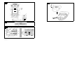
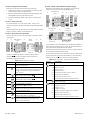
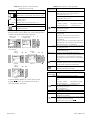
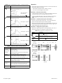
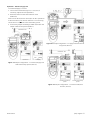
GE
Sensing
Druck DPI 880
Multi-function calibrator
User manual - K405
Customer service
A1
B1
10
A2
1
9
A3
8
2
7
3
6
11
4
5
B1
12
A2
13
15
14
A3
19
18
A
3
20
21
22
23
24
K405 Issue 3
17
16
25
Visit our web site: www.gesensing.com
Table of Contents
Introduction ......................................................................... 2
Safety ..................................................................................... 2
Marks and symbols on the instrument ................................. 2
To start .................................................................................. 3
Key to figure A1/A2 (Instrument) ............................................. 3
Key to figure A3 (Display) ............................................................. 3
Prepare the instrument ................................................................ 4
Power on or off ................................................................................ 4
Set up the basic operation ......................................................... 4
Select a task (Measure and/or supply) .................................. 4
Set up the settings ......................................................................... 5
Specification ......................................................................
General .............................................................................................
Electrical (A1 - Item 10) .............................................................
Electrical connectors (A2) ........................................................
Temperature ranges (RTD) ......................................................
Resistance ranges (Ohms/RTD) .............................................
Frequency .......................................................................................
Temperature ranges (TC) .........................................................
mV (TC) range ................................................................................
17
17
17
17
18
18
18
19
19
Customer service ................................................Back cover
Operation .............................................................................. 6
Electrical connections .................................................................. 6
Communications port connections ........................................ 6
Change the output values .......................................................... 6
Measure/supply mA ...................................................................... 7
Measure/supply Volts or mV ..................................................... 8
Measure/supply Hz or pulses .................................................... 8
RTD/Ohms connections ............................................................... 8
Measure/simulate an RTD or Ohms ....................................... 9
Thermocouple (TC) connections .............................................. 9
Measure/simulate a Thermocouple .................................... 10
Transmitter calibration ............................................................. 10
Switch test ....................................................................................... 11
UPM Pressure measurements ............................................... 11
Error indications ........................................................................... 12
Maintenance ..................................................................... 12
Clean the unit ................................................................................ 12
Replace the batteries ................................................................. 12
Calibration .........................................................................
Before you start ............................................................................
Procedures: mA input ................................................................
Procedures: mA output .............................................................
Procedures: mV/Volts input ....................................................
Procedures: mV/Volts output .................................................
Procedures: Hz input/output ..................................................
Procedures: CJ input ..................................................................
Procedures: RTD (Ohms) input ...............................................
Procedures: RTD (Ohms) output ............................................
Procedures: TC (mV) input/output ........................................
Procedures: IDOS UMM .............................................................
13
13
14
14
14
15
15
16
16
16
17
17
© 2006 General Electric Company. All rights reserved.
Trademarks
All product names are trademarks of their respective companies.
K405 Issue 3
[EN] English - 1
Introduction
The DPI 880 Multi-function Calibrator is part of the
Druck DPI 8xx series of hand held instruments.
This series of instruments uses Intelligent Digital Output
Sensor (IDOS) technology to give instant plug and play
functionality with a range of Universal Measurement
Modules (UMM). Example: the Universal Pressure Module
(UPM).
The DPI 880 includes these functions:
Function
* Measure mA, Volts/mV, Hz/pulse count
* Supply mA, Volts/mV, Hz/pulse count
* Measure/simulate:
- a Resistance Temperature Detector (RTD): Ω or °C/°F
- a thermocouple (TC): mV or °C/°F
- a resistor (Ω)
Cold Junction (CJ) compensation: Automatic/Manual
Step/Ramp functions: Automatic/Manual
Communications port: IDOS or RS232
Language selection (Refer to Table 1)
** Measure pressure/Leak test: External IDOS UPM
** Snapshot: Up to 1000 displays with a date/time stamp
250Ω series resistor. Use this instrument together with a HART®
communicator to set up and calibrate HART® devices.
Switch test
Other functions: Hold, Backlight
*
**
Refer to “Specification”.
Optional item
Safety
Before you use the instrument, make sure that you read
and understand all the related data. This includes: all local
safety procedures, the instructions for the UMM (if
applicable), and this publication.
WARNING
• It is dangerous to ignore the specified limits for the
instrument or to use the instrument when it is not in
its normal condition. Use the applicable protection
and obey all safety precautions.
• Do not use the instrument in locations with explosive
gas, vapor or dust. There is a risk of an explosion.
• To prevent electrical shocks or damage to the
instrument, do not connect more than 30V between
the terminals, or between the terminals and the
ground (earth).
• UPM only. To prevent a dangerous release of
pressure, isolate and bleed the system before you
disconnect a pressure connection.
Before you start an operation or procedure in this
publication, make sure that you have the necessary skills
(if necessary, with qualifications from an approved training
establishment). Follow good engineering practice at all
times.
Safety - Marks and symbols on the instrument
Complies with European
Union directives
Warning - refer to the
manual
Read the manual
Battery
Ground (Earth)
ON/OFF
Do not dispose of this product as household waste. Refer to
“Maintenance”.
More marks and symbols are specified in “To start”.
2 - [EN] English
K405 Issue 3
To start
To start - Key to figure A3 (Display)
To start - Key to figure A1/A2 (Instrument)
Item
1.
2.
Description
❍
■■
3.
ESC
4.
5.
6.
7.
Increases or decreases a value.
Highlights a different item.
Holds the data on the display. To continue, press the
HOLD
HOLD button again.
Shows the task selection menu (Item 25).
MENU
Selects or accepts an item or value.
OK
Selects [✓] or cancels [ ] a selection.
▲
▼
■■
8.
9.
On or off button.
Left-hand soft-key. Selects the function above it on
the display (Item 24). Example: Edit
Moves back one menu level.
Leaves a menu option.
Cancels the changes to a value.
SENSOR
/ PC
10.
11.
12.
13. 14. 15
Right-hand soft-key. Selects the function above it on
the display (Item 24). Example: Settings
Display. Refer to A3
Communications port. Use to connect a Universal
Measurement Module (UMM) or a RS232 cable.
Connectors to measure or supply the specified
values. Refer to “Operation”.
COM
Common connector
3W, 4W 3-wire, 4-wire RTD input
Connection point for some of the optional
accessories. Refer to the datasheet.
Battery compartment. Refer to B1.
(Dual Function) Connectors to measure or supply the
specified values. Refer to “Operation”.
Volts input or switch
Vin,
24Vo
Item
Description
16.
Task indication for the switch test.
= switch closed
= switch open
UPM only. Task indication for the leak test.
There is a 250Ω series resistor in the mA circuit.
Refer to: Table 2/3
17.
The loop power supply is on.
Refer to: Table 2/3
The data on the display is on hold. To continue, press
the HOLD button again.
18.
19.
Shows the battery level: 0 to 100%.
20.
Identifies the type of data.
= Input
= Output
= IDOS input
Refer to: Table 2/3
21. to 22.
The settings applied to the input or output:
21.
K
The thermocouple type (K, J, T ... ) - (Table 4/5).
CJ= ... The cold junction temperature (Table 1)
Pt...
5.0V
22.
The RTD type (Pt50, ...) - (Table 4/5).
RTD input connections: 2, 3, or 4 (Figure 7)
...V
The input trigger level (Table 4) or the output
amplitude (Table 5).
, ... ,
=
Output operation (Table 5)
23.
The measured values applicable to the task
13.400
selections in item 25, area ➀ and ➁
55mA
+ the measurement range and units.
24.
A soft-key function. To select an available function,
Sk1/2
press the soft-key below it. Example:
24V loop power supply
= Move left
25.
= Move right
The task selection menu. One task selection is
permitted in each area (➀ and ➁).
= cursor position (flashes on/off)
= a button or task selection is set in area ➀ or ➁.
Sets the Dual Function, area ➁ selections to off. This
saves the battery power.
Refer to: Table 2/3
Help: Shows a connection diagram for the task
selections you have set.
Set Up: Shows the Set Up menu to set up the basic
operation. Refer to Table 1.
OK: Accepts the selections on the menu.
Note: MENU/OK also does this.
Utilities: Leak Test. Use this function with a UPM. Refer
to Figure 13.
Snapshot: Optional item - To use this facility, install
the data logging upgrade kit. Refer to the user
manual - K397: DPI 800 series data logging upgrade
kit.
K405 Issue 3
[EN] English - 3
To start - Prepare the instrument
Before you use the instrument for the first time:
• Make sure that there is no damage to the instrument,
and that there are no missing items.
• Remove the plastic film that protects the display. Use
the tag (◗ ) in the top right-hand corner.
• Install the batteries (refer to B1). Then re-attach the
cover.
To start - Power on or off
To set the power on or off, press ❍ (A1 - item 1). The
instrument does a self test and then shows the applicable
data.
When the power is off, the last set of configuration options
stays in memory. Refer to “Maintenance”.
To start - Select a task (Measure and/or supply)
When the instrument is set up (Table 1), use the task
selection menu to select the applicable task.
1
Task selection
menu:
2
3
▲
▼
+
■■
(Table 2/3)
Task selection
menu:
4
5
▲
▼
+
■■
Task = mA output
Display:
mA output
6
To start - Set up the basic operation
Use the Set Up menu to set up the basic operation of the
instrument.
1
2
Task selection
menu:
3
Menu:
Set Up
▲
▼
+
■■
4
5
▲
▼
(Table 2)
(Table 1)
[✓]/[ ]
If there is additional data for a menu option, select
Settings (■ ■) to see the values that are set up. If
necessary, adjust the values.
Table 1: Menu options - Set Up
Options
Description
... Scale To select the applicable international temperature
scale: IPTS 68 or ITS 90.
To add a 250Ω series resistor into the mA circuit.
You can then use this instrument together with a
HART® communicator to set up and calibrate
HART® devices.
To select and set up the backlight facility + timer.
Additional data: Select Settings (■ ■)
To select and set up the power off facility + timer.
Additional data: Select Settings (■ ■)
To show the battery level (%).
To set the display contrast (%).
▲ Increases %, ▼ decreases %
To set the time + date. The calibration facility uses
the date to give service and calibration messages.
To set the language option.
To calibrate the instrument.
Additional data: Refer to “Calibration”.
To select and show the applicable status data.
(Software Build, Calibration Due date, Serial
Number, IDOS Information).
4 - [EN] English
Sk1 = Edit
Sk2 = Settings
(Table 2/3)
If you attach a Universal Measurement Module (UMM) to
the communications port (A1 - item 9), the task selection
menu shows the applicable IDOS options.
Make the necessary selections from each area (➀ and ➁).
One task is permitted in each area.
Note: Use the Dual Function area (➁) to do two operations
at the same time. If the area ➁ selection is not necessary,
set this area to off (■). This saves the battery power.
Table 2: Menu options - Task selections (Area ➀)
Options
(If applicable)
Description
Input measurement tasks:
mA Measure ±55 mA
V Measure ±30V
mV Measure ±120mV
Hz Measure the frequency (Units: Table 4)
RTD Measure RTD temperature
Ω Measure RTD resistance or Ω
TC Measure thermocouple temperature OR mV
Only when an IDOS UMM is attached. An IDOS
measurement task.
Output tasks:
mA Supply 0 to 24 mA
V Supply 0 to 12V
mV Supply 0 to 120mV
Hz Supply an output frequency (Units: Table 4)
RTD Simulate RTD temperature
Ω Simulate RTD resistance or Ω
TC Simulate thermocouple temperature OR mV
K405 Issue 3
Table 4: Menu options - Settings (Input)
Table 3: Menu options - Task selections
(Dual Function, area ➁)
Options
(If applicable)
Description
White button = A Dual Function is set.
Black button = Dual Function, area ➁ is set to off.
Options
Description
(If applicable)
... Units Pressure Units (UPM only). If you select an IDOS task
(Table 2/3). Select one of the fixed units of
measurement (psi, mbar ... ).
Temperature Units (RTD or TC only). To select the
temperature units (°C or °F).
Frequency Units (Hz only). To select one of these
units:
Hz: Range < 1000Hz
kHz: Range 0 to 50kHz
Input measurement tasks:
mA Measure ±55 mA
V Measure ±30V
mA/24V Measure ±55 mA (24V loop power is on)
A switch test
Only when an IDOS UMM is attached. An IDOS
measurement task.
...
To start - Set up the settings
When the task is set up (Table 2/3), use the Settings menu
to adjust the input and/or output operation.
Display: Task
mA + IDOS
1
Settings selection
(If applicable)
2
3
Sk1 = Start/Stop
Sk2 = Settings
Menu:
Settings
... Units
4A
5A
Display:
... units
bar
▲
▼
Pa
(Table 4)
Menu:
Settings
6A
(Table 4)
4B
7A
... type Select RTD Type (RTD only). To select an applicable
RTD type (Pt50, Pt100 ... )
Select TC Type (TC only). To select an applicable
thermocouple type (K, J, T ... )
Trigger level
(Hz only). To set the amplitude at which the
instrument senses a frequency signal. Default = 5V.
Auto Detect [✓]/[ ]: Set this option to make the
instrument calculate the value from the available
signal.
(UPM only). Gage sensors or sensors with
differential operation. A zero correction that makes
the instrument read zero at local pressure.
▲
▼
[●]
5B
(Leak Test only). To set an applicable period for the
leak test (Hours:Minutes:Seconds).
Table 5: (Part of table) Menu options - Settings (Output)
▲
▼
(Table 5)
CJ ... (TC only). To select the type of cold junction (CJ)
compensation.
Automatic: The instrument monitors the CJ
temperature and applies the necessary CJ
compensation.
Manual: Measure the CJ temperature and set the
applicable value. The instrument uses this value to
apply the necessary CJ compensation.
▲
▼
■■
counts/minute (cpm)
counts/hour (cph)
(TC only). Change the measurement operation:
Temperature to mV OR
mV to Temperature
[●]
Options
Description
(If applicable)
... Units Pressure/Temperature: Refer to Table 4.
Frequency Units (Hz only). To select one of these
units:
Hz: Range < 1000Hz
kHz: Range 0 to 50kHz
pulses/minute (ppm)
pulses/hour (pph)
If there is additional data for a menu option, select
Settings (■ ■) to see the values that are set up. If
necessary, adjust the values.
...
(TC only). Change the output operation:
Temperature to mV OR
mV to Temperature
CJ ... (TC only). Refer to Table 4.
... type Refer to Table 4.
Amplitude
(Hz only). To set the amplitude of the output signal.
Amplitude = 5V (Default).
To select and set up a value for the “Nudge” output.
Example: 1.000 mA increments.
Additional data: Select Settings (■ ■)
K405 Issue 3
[EN] English - 5
Table 5: (Part of table) Menu options - Settings (Output)
Options
(If applicable)
Description
To select and set up values for the “Span Check”
output. Example output cycle:
This cycle repeats
automatically.
Operation
This section gives examples of how to connect and use the
instrument. Before you start:
• Read and understand the “Safety” section.
• Do not use a damaged instrument.
Operation - Electrical connections
To prevent instrument errors, make sure that the electrical
connections (A1-item 10 and/or A2) are correct.
Additional data (Table 6): Select Settings (■ ■)
% Step
To select and set up values for the “% Step” output.
Example output cycle:
Auto Repeat - Optional
Additional data (Table 6): Select Settings (■ ■)
... Step
To select and set up values for the “Defined Step”
output. Example output cycle:
The Help button (A3 - Item 25) shows a connection
diagram for the task selections you have set.
Operation - Communications port connections
Use the communications port (A1 - item 9) to attach an
IDOS Universal Measurement Module (UMM).
When you attach the cable from a UMM (Figure 13/14), the
instrument automatically changes the menus to give you
all the applicable options (Table 2/3).
Operation - Change the output values
When the output operation is set up (Table 5), use one of
these procedures to change the output values:
Table 7: Procedures to change the output
Auto Repeat - Optional
Output
Additional data (Table 6): Select Settings (■ ■)
To select and set up values for the “Ramp” output.
Example output cycle:
,
Procedure
Select Edit (■ ■) and/or use the ▲ ▼ buttons.
See the example below.
Select Start/Stop (■ ■) or use the ▲ ▼ buttons
to make the step changes manually.
Select Start/Stop (■ ■).
Auto Repeat - Optional
Example procedure (“Nudge” output):
Display:
mA output
1
Edit
2
3
Edit
4
Additional data (Table 6): Select Settings (■ ■)
Table 6: Additional data for Settings (Output):
Item
Span Check
Low (0%)
High (100%)
Dwell (d)
Set the 0% value.
Set the 100% value.
Set the period (Hours:Minutes:Seconds) between
each change in value.
% Step
Low (0%), High (100%), Dwell (d): As above.
Step Size (s) ... Set the change in value for each step as a
%
percentage of the full-scale range (High - Low).
Defined Step
Step Size (s)
Ramp
■■
Value
Low (0%), High (100%), Dwell (d): As above.
Set the change in value for each step.
Example: 1.000 mA steps.
Low (0%), High (100%), Dwell (d): As above.
Travel (t)
Set the period (Hours:Minutes:Seconds) to go from
the Low (0%) value to the High (100%) value.
Auto Repeat
If applicable, select this item to repeat a cycle
continuously.
6 - [EN] English
■■
▲
+01.000
▼
Sk1 = Edit
Sk2 = Settings
Display:
mA output
5
▲
▼
6
2.000
▲
▼
3.000
Increment = 1.000
(Table 5)
K405 Issue 3
Operation - Measure/supply mA
To measure/supply a current:
1. Connect the instrument (Figure 1, 2 or 3) and, if
necessary, adjust the Set Up (Table 1).
2. Select the task from the task selection menu
(Table 2/3).
Note: Use the Dual Function area (➁) to do two operations
at the same time. If the area ➁ selection is not necessary,
set this area to off (■). This saves the battery power.
3. If necessary, adjust the Settings (Table 4/5) and/or the
output values to the system (Table 7).
Maximum: 30V
Edit
Settings
Figure 2: Example configuration - To supply mA with internal
loop power (Area ➀)
Maximum: 30V
Edit
a) Measure
Settings
b) Supply
Figure 1: Example configuration - To measure/supply mA
with external loop power (Area ➀)
a) with external loop
power
b) with internal loop
power
Figure 3: Example configuration - To measure mA (Dual
Function, area ➁)
K405 Issue 3
[EN] English - 7
Operation - Measure/supply Volts or mV
To measure/supply Volts or mV:
Operation - Measure/supply Hz or pulses
To measure/supply Hz or pulses:
1. Connect the instrument (Figure 4/5) and, if necessary,
adjust the Set Up (Table 1).
1. Connect the instrument (Figure 6) and, if necessary,
adjust the Set Up (Table 1).
2. Select the task from the task selection menu
(Table 2/3).
2. Select the task from the task selection menu (Table 2):
Note: Use the Dual Function area (➁) to do two operations
at the same time. If the area ➁ selection is not necessary,
set this area to off (■). This saves the battery power.
3. If necessary, adjust the Settings (Table 4/5) and/or the
output values to the system (Table 7).
3. If necessary, adjust the Settings (Table 4/5) and/or the
output values to the system (Table 7).
0 to ±30V OR
0 to ±120mV
0 to 12V OR
0 to 120mV
Settings
a) Input
Edit
a) Measure
Settings
b) Supply
Figure 4: Example configuration - To measure/supply Volts
or mV (Area ➀)
0 to ±30V
Edit
Settings
b) Output
Figure 6: Example configuration - To measure/supply Hz
or Pulses
For an input, the display shows the condition of the
frequency gate:
= Gate open (measurement starts)
= Gate closed (measurement is waiting for the next
rising edge of the cycle)
= Fast cycle
Operation - RTD/Ohms connections
In the examples that follow 2W, 3W, and 4W identify the 2,
3, and 4-wire connections for a RTD or resistance.
Figure 5: Example configuration - To measure Volts (Dual
Function, area ➁)
8 - [EN] English
K405 Issue 3
Operation - Measure/simulate an RTD or Ohms
To measure/simulate RTD values or Ohms:
1. Connect the instrument (Figure 7/8) and, if necessary,
adjust the Set Up (Table 1).
2. Select the task from the task selection menu (Table 2):
3. If necessary, adjust the Settings (Table 4/5) and/or the
output values to the system (Table 7).
Pt100
°C
Edit
Settings
a) RTD °C or °F
Settings
b) Ohms (Ω)
Figure 8: Example configuration - To simulate the
temperature or resistance
Operation - Thermocouple (TC) connections
Attach the TC wires to the applicable TC mini-connector
(Figure 9). The wider blade is the negative. Then attach the
connector to the instrument.
Settings
a) RTD °C or °F
Edit
b) Ohms (Ω)
Figure 7: Example configuration - To measure the
temperature or resistance
For an input, the display shows the number of RTD or
resistance connections.
= Four-wire RTD attached.
If this symbol does not agree with the number of
connections:
• Make sure that the connections are correct.
• Make sure that the wires and the sensor are
serviceable.
K405 Issue 3
[EN] English - 9
Operation - Measure/simulate a Thermocouple
To measure/simulate the TC values:
Operation - Transmitter calibration
To calibrate a transmitter:
1. Connect the instrument (Figure 9) and, if necessary,
adjust the Set Up (Table 1).
1. Connect the instrument (Figure 10/11) and, if
necessary, adjust the Set Up (Table 1).
2. Select the task from the task selection menu (Table 2).
2. Select the applicable calibration task from the task
selection menu (Table 2/3) and, if necessary, adjust the
Settings (Table 4/5).
3. Select Settings (■ ■) to change the operation from
Temperature to mV or mV to Temperature.
4. If necessary, adjust the Settings (Table 4/5) and/or the
output values to the system (Table 7).
3. Supply the output values to the system (Table 7).
Maximum: 30V
K
°C
Settings
Edit
Settings
a) °C or °F (Input)
Settings
Settings
b) mV (Input)
Figure 10: Example configuration - Transmitter calibration
with external loop power
Settings
Edit
Settings
c) °C or °F (Output)
Edit
Settings
d) mV (Output)
Figure 9: Example configuration - To measure/simulate the
temperature (°C/°F) or mV values of a TC
10 - [EN] English
Edit
Settings
Figure 11: Example configuration - Transmitter calibration
with internal loop power
K405 Issue 3
Operation - Switch test
To do tests on a switch:
1. Connect the instrument (Figure 12) and, if necessary,
adjust the Set Up (Table 1).
Operation - UPM Pressure measurements
Read all the instructions supplied with the UPM and then
use the specified procedures to connect it (Figure 13/14).
2. Select the applicable switch test from the task
selection menu (Table 2/3) and, if necessary, adjust the
Settings (Table 5). The display shows the switch
condition (open or closed) in the top right-hand corner.
3. Supply the output values to the system (Table 7).
• Example - “Nudge” output.
a. Use Edit (■ ■) to set a value less than the switch
value.
b. Use the ▲ ▼ buttons to change the value in small
increments.
• Example - “Ramp” output.
a. Set “High” and “Low” values that are applicable to
the switch value (Table 6). Then, to get an accurate
switch value, set a long “Travel” period.
b. Use Start/Stop (■ ■) to start and stop the “Ramp”
cycle.
4. If necessary, supply the output values in the opposite
direction until the switch changes condition again.
The display shows the applicable values to open and
close the switch.
5. To do the test again, press ESC to reset the values.
Settings
a) Pressure
Start
Settings
b) Leak test
Figure 13: Example configuration - Pressure measurement
with a UPM
When the connections are complete, make the necessary
IDOS selections (Table 2/3).
Each time you use a different UPM, the DPI 880 records its
measurement units (capacity: the last 10 different UPM).
When you re-attach one of the last 10 UPM, the DPI 880
automatically uses the applicable units (psi, mbar ... ).
UPM - Measure the pressure/leak test
To measure the pressure with or without a leak test
(Figure 13):
1. Select the applicable pressure task from the task
selection menu (Table 2/3) and, if necessary, adjust the
Set Up (Table 1), and the Settings (Table 4/5).
Utilities function: Use this function to include the
Leak Test option.
2. If applicable, set the period for the leak test (Table 4).
3. If necessary, do a zero correction (Table 4).
Edit
Settings
Figure 12: Example configuration - Switch test
K405 Issue 3
4. To start the leak test, select Start (■ ■). When the test is
finished, the instrument calculates the leak rate in the
applicable units/minute.
To measure pressure with another operation (Figure 14),
use the same procedure.
[EN] English - 11
Maintenance
This section gives procedures to maintain the unit in a
good condition. Return the instrument to the
manufacturer or an approved service agent for all repairs.
Do not dispose of this product as household waste. Use an
approved organisation that collects and/or recycles waste
electrical and electronic equipment.
For more information, contact one of these:
• our customer service department:
(Contact us at www.gesensing.com)
• your local government office.
Maintenance - Clean the unit
Clean the case with a moist, lint-free cloth and a weak
detergent. Do not use solvents or abrasive materials.
Maintenance - Replace the batteries B1
To replace the batteries, refer to B1. Then re-attach the
cover.
Make sure that the time and date are correct. The
calibration facility uses the date to give service and
calibration messages.
All the other configuration options stay in memory.
Settings
Figure 14: Example configuration - To measure pressure
and temperature
Operation - Error indications
If the display shows <<<< or >>>> :
• Make sure that the range is correct.
• Make sure that all the related equipment and
connections are serviceable.
12 - [EN] English
K405 Issue 3
Calibration
Note: GE can provide a calibration service that is traceable
to international standards.
We recommend that you return the instrument to the
manufacturer or an approved service agent for
calibration.
If you use an alternative calibration facility, make sure that
it uses these standards.
Calibration - Before you start
To do an accurate calibration, you must have:
• the calibration equipment specified in Table 8.
• a stable temperature environment: 70 ± 2°F (21 ± 1°C)
Table 8: Calibration equipment
Function
mA OR
mA (Dual ... )
mV OR
TC (mV)
Volts OR
Volts (Dual ... )
Hz
IDOS
CJ
RTD Ohms
RTD Ohms
*
Calibration equipment
(ppm = parts per million)
mA calibrator.
Accuracy - mA input/output: Table 10/11
Accuracy - mA (Dual Function): Table 10
mV calibrator.
Accuracy - mV input/output: Table 12/14
Accuracy - TC (mV): Table 20
Volts calibrator.
Accuracy - Volts input/output: Table 13/ 15.
Accuracy - Volts (Dual Function): Table 13
1) Frequency meter
Total error: 7 ppm or better
Resolution: 8 digits (minimum)
2) Signal generator
UMM only. Refer to the user manual for the IDOS
UMM.
- Standard RTD probe
Accuracy: 50 mK for 23 to 82.4°F (-5 to 28°C)
- Digital thermometer
Accuracy: 10 mK
- Standard 0Ω resistor
- *Standard resistor (Ω): 100, 200, 300
Tolerance: 50 ppm + 0.6 ppm/°C + 5 ppm/year
- *Standard resistor (Ω): 400, 1k, 2k, 4k
Tolerance: 10 ppm + 0.6 ppm/°C + 5 ppm/year
An ohmmeter or an RTD measurement system
with the specified excitation currents (Table 19).
Before you start the calibration, make sure that the time
and date on the instrument are correct (Table 1).
Selection sequence:
➤ Task selection menu ➤ Set Up (Table 1) ➤ Calibration ➤
Display: Enter
Calibration PIN
1
2
3
Menu:
Select Channel
▲
▼
+
■■
Factory PIN = 4321
Select Function
(If applicable)
5a
4
5
▲
▼
(Table 9)
5b
▲
▼
(Table 9)
Table 9: Calibration options
Options
... ➤
IDOS
CJ
mA (Dual ... )
Description
... To calibrate the specified input/output:
... ... = mA, mV, Volts, Hz, RTD (Ohms), TC (mV)
UMM only. To calibrate the specified IDOS UMM.
Refer to the user manual for the IDOS UMM.
To calibrate the cold junction channel.
To calibrate the mA (Dual Function) input.
Volts (Dual ... ) To calibrate the Volts (Dual Function) input.
Calibration Due: To set the date of the next
calibration for the instrument.
After the specified calibration date, there is a
warning message. There is a selection box to stop
the warning.
To change the calibration PIN (Personal
Identification Number).
When you select a channel/function, the display shows the
applicable instructions to complete the calibration.
When the calibration is complete, select Calibration Due
and set the new calibration date for the instrument.
Or an equivalent resistance simulator
K405 Issue 3
[EN] English - 13
Table 11: mA output error limits
Calibration - Procedures: mA input
1. Connect the instrument to the calibration equipment
(Figure 3).
2. Let the equipment get to a stable temperature
(minimum: 5 minutes since the last power on).
3. Use the calibration menu (Table 9) to do a three-point
calibration (-FS, Zero and +FS). The display shows the
applicable instructions to complete the calibration.
4. To make sure that the calibration is correct, select the
applicable mA input task (Table 2) and apply these
values:
Output
mA
Calibrator
error
(mA)
0.000 006
0.000 20
0.001 4
0.002
0.002 3
0.1
4
12
20
24
Permitted
DPI 880 error
(mA)
0.001
0.001
0.001
0.002
0.002
Calibration - Procedures: mV/Volts input
1. Connect the instrument to the calibration equipment
(Figure 4).
• mA: -55, -40, -24, -18, -12, -6, 0 (open circuit)
Then mA: 0, 6, 12, 18, 24, 40, 55.
2. Let the equipment get to a stable temperature
(minimum: 5 minutes since the last power on).
5. Make sure that the error is in the specified limits
(Table 10).
3. Use the calibration menu (Table 9) to do a three-point
calibration (-FS, Zero and +FS). The display shows the
applicable instructions to complete the calibration.
Table 10: mA input error limits
Applied
mA
Calibrator
error
(mA)
Permitted
DPI 880 error
(mA)
±55
±40
0.002 2
0.001 8
0.005
0.004
±24
±18
±12
0.001 4
0.000 4
0.000 3
0.003
0.003
0.002
±6
0 (open circuit)
0.000 2
-
0.002
0.001
Calibration - Procedures: mA output
1. Connect the instrument to the calibration equipment
(Figure 1).
2. Let the equipment get to a stable temperature
(minimum: 5 minutes since the last power on).
3. Use the calibration menu (Table 9) to do a two-point
calibration (Zero and +FS). The display shows the
applicable instructions to complete the calibration.
4. To make sure that the calibration is correct, select the
applicable mA output task (Table 2) and set these
output values:
• mA: 0.1, 4, 12, 20, 24
5. Make sure that the error is in the specified limits
(Table 11).
14 - [EN] English
4. To make sure that the calibration is correct, select the
applicable mV or Volts input task (Table 2).
5. Then apply the input values that are applicable to the
calibration:
• mV: -120, -60, -30, 0 (short circuit)
Then mV: 0, 30, 60, 120
OR
• Volts (V): -30, -15, -5, 0 (short circuit)
Then volts (V): 0, 5, 15, 30
6. Make sure that the error is in the specified limits
(Table 12 or Table 13).
Table 12: mV input error limits
Applied
mV
±120
±60
±30
0 (Short circuit)
Calibrator
error
(mV)
0.001 3
0.000 8
0.000 6
-
Permitted
DPI 880 error
(mV)
0.03
0.02
0.02
0.01
Table 13: Volts (V) input error limits
Applied
V
±30
±15
±5
0 (Short circuit)
Calibrator
error
(V)
0.000 58
0.000 11
0.000 06
-
Permitted
DPI 880 error
(V)
0.004
0.002
0.001
0.001
K405 Issue 3
Calibration - Procedures: mV/Volts output
1. Connect the instrument to the calibration equipment
(Figure 4).
3. Set up the equipment with these conditions:
Frequency meter:
Signal generator:
2. Let the equipment get to a stable temperature
(minimum: 5 minutes since the last power on).
3. Use the calibration menu (Table 9) to do a two-point
calibration (Zero and +FS). The display shows the
applicable instructions to complete the calibration.
DPI 880:
Gate time = one second
Output = 10V, unipolar,
square wave
Frequency = 990 Hz
Input units = Hz (Table 4)
Input trigger level = 5V (Table 4)
4. To make sure that the calibration is correct, select the
applicable mV or Volts output task (Table 2).
4. Use the calibration menu (Table 9) to do the calibration.
The display shows the applicable instructions to
complete the calibration.
5. Then set the output values that are applicable to the
calibration:
5. To make sure that the calibration is correct, set up the
equipment to do one of these calibration checks:
• mV: 0, 30, 60, 90, 120
OR
• Volts (V): 0, 3, 6, 9, 12
• Hz input calibration check (Figure 6):
6. Make sure that the error is in the specified limits
(Table 14 or Table 15).
Table 14: mV output error limits
Output
mV
Calibrator
error
(mV)
0.000 05
0.000 425
0.000 8
0.001 175
0.000 98
0
30
60
90
120
Permitted
DPI 880 error
(mV)
0.01
0.02
0.03
0.03
0.04
Table 15: Volts (V) output error limits
Output
V
0
3
6
9
12
Calibrator
error
(V)
0.000 000 05
0.000 017 5
0.000 03
0.000 05
0.000 134
Permitted
DPI 880 error
(V)
0.001
0.002
0.002
0.002
0.002
Calibration - Procedures: Hz input/output
1. Connect the instrument to the calibration equipment
(Figure 6).
2. Let the equipment get to a stable temperature
(minimum: 5 minutes since the last power on).
K405 Issue 3
Frequency meter:
Signal generator:
DPI 880:
Gate time = one second
Output = 10V, unipolar,
square wave
Input trigger level = 5V (Table 4)
Units (Table 4): Hz or kHz as
specified in Table 16/17.
• Hz output calibration check (Figure 6):
Frequency meter:
DPI 880:
Gate time = one second
Units (Table 5): Hz or kHz as
specified in Table 16/17.
6. Measure or supply the specified values (Table 16/17):
Hz then kHz. Make sure that the error is in the specified
limits.
Table 16: Hz error limits (Measure/Supply)
Measure/
Supply
Hz
25
100
250
500
990
Calibrator
error (Hz)
Permitted
DPI 880 error (Hz)
0.000 175
0.000 7
0.001 75
0.003 5
0.006 93
0.002
0.002
0.004
0.006
0.011
0.001 4
0.002 1
0.003 5
0.005 8
0.010 4
Table 17: kHz error limits (Measure/Supply)
Measure/
Supply
kHz
2.500 0
10.000 0
20.000 0
30.000 0
50.000 0
Calibrator
error (kHz)
Permitted
DPI 880 error (kHz)
0.017 5
0.07
0.14
0.21
0.35
0.000 2
0.000 2
0.000 3
0.000 4
0.000 6
0.000 042
0.000 112
0.000 205
0.000 298
0.000 483
[EN] English - 15
Calibration - Procedures: CJ input
Calibration - Procedures: RTD (Ohms) output
1. Connect the instrument to the calibration equipment
(Figure 9).
1. Connect the instrument to the calibration equipment
(Figure 8).
2. Let the equipment get to a stable temperature
(minimum: 5 minutes since the last power on).
2. Let the equipment get to a stable temperature
(minimum: 5 minutes since the last power on).
3. Use the calibration menu (Table 9) to do a one-point
calibration (+FS). The display shows the applicable
instructions to complete the calibration.
3. Use the calibration menu (Table 9) to do a two-point
calibration for each range.
4. To make sure that the calibration is correct, select the
applicable T1 input task (Table 2).
5. Make sure that the DPI 880 gives a probe temperature
that agrees with the temperature on the digital
thermometer ±0.2°F (0.1°C).
Calibration - Procedures: RTD (Ohms) input
1. Let the equipment get to a stable temperature
(minimum: 5 minutes since the last power on).
• Range: 0-399.9Ω
• Range: 400Ω-1999.9Ω
• Range: 2kΩ-4kΩ
The display shows the applicable instructions to
calibrate each range.
4. To make sure that the calibration is correct, select the
applicable ohms output task (Table 2).
5. Supply the specified values (Table 19). Make sure that
the error is in the specified limits.
Table 19: RTD (Ohms) output error limits
2. Use the calibration menu (Table 9) to do a two-point
calibration for each range.
• Range: 0-399.9Ω
a. Nominal zero ohms: Make a 4 wire connection to
the 0Ω resistor (Figure 7).
b. Nominal positive full-scale ohms: Make a 4 wire
connection to the 400Ω resistor (Figure 7).
• Range: 400Ω-4kΩ
a. Nominal zero ohms: Make a 4 wire connection to
the 400Ω resistor (Figure 7).
b. Nominal positive full-scale ohms: Make a 4 wire
connection to the 4kΩ resistor (Figure 7).
The display shows the applicable instructions to
calibrate each range.
Ohms
(Ω)
Excitation
(mA)*
0.50 to 3.0
Calibrator
error
(Ω)
0.003
Permitted
DPI 880 error
(Ω)
0.05
0
100
200
300
0.50 to 3.0
0.50 to 3.0
0.50 to 3.0
0.004
0.005
0.007
0.06
0.06
0.07
400
1000
0.50 to 3.0
0.05 to 0.8
0.008
0.015
0.07
0.30
2000
4000
0.05 to 0.4
0.05 to 0.3
0.026
0.049
0.40
0.80
*
Refer to “Specification”
3. To make sure that the calibration is correct, select the
applicable ohms input task (Table 2).
4. Make a 4 wire connection to the applicable standard
resistor (Table 18) and measure the value (Figure 7).
5. Make sure that the error is in the specified limits
(Table 18).
Table 18: RTD (Ohms) input error limits
Standard
Resistor*
(Ω)
Resistor
error
(Ω)
Permitted
DPI 880 error
(Ω)
0 (Short circuit)
100
0.008
0.05
0.05
200
300
400
0.013
0.018
0.007
0.05
0.05
0.05
1k
2k
4k
0.042
0.052
0.072
0.25
0.25
0.50
*
Or an equivalent resistance simulator
16 - [EN] English
K405 Issue 3
Calibration - Procedures: TC (mV) input/output
1. Connect the instrument to the calibration equipment:
• TC (mV) input = Figure 9b
• TC (mV) output = Figure 9d
3. Use the calibration menu (Table 9) to do the calibration:
• TC (mV) input = three-point calibration
(-FS, Zero and +FS).
• TC (mV) output = two-point calibration (Zero and +FS).
The display shows the applicable instructions to
complete the calibration.
4. To make sure that the calibration is correct, select the
applicable TC (mV) input or output task (Table 2) and
apply the necessary values:
• TC (mV) input: -10, 0 (short circuit)
Then TC (mV): 25, 50, 75
• TC (mV) output: -10, 0, 25, 50, 75
5. Make sure that the error is in the specified limits
(Table 20).
Table 20: TC (mV) input/output error limits
Calibrator error
TC (mV)
mV
mV
0.000 5
0.000 18
0.000 05
0.000 6
0.000 36
0.000 8
0.000 68
0.001 0
0.000 99
All accuracy statements include one year stability.
Specification - General
2. Let the equipment get to a stable temperature
(minimum: 5 minutes since the last power on).
Input
or output
TC (mV)
-10
0
25
50
75
Specification
Permitted DPI 880 error
TC (mV)
mV
mV
0.008
0.008
0.006
0.006
0.010
0.010
0.014
0.014
0.018
0.018
Calibration - Procedures: IDOS UMM
Refer to the user manual for the IDOS UMM.
When the calibration is complete, the instrument
automatically sets a new calibration date in the UMM.
Languages
Operating
temperature
Storage
temperature
Humidity
Shock/Vibration
EMC
Safety
Size (L: W: H)
Weight
Power supply
Duration
English [Default]
14 to 122°F (-10 to 50°C)
-4 to 158°F (-20 to 70°C)
0 to 90% without condensation
(Def Stan 66-31, 8.6 cat III)
BS EN 61010:2001; Def Stan 66-31, 8.4 cat III
BS EN 61326-1:1998 + A2:2001
Electrical - BS EN 61010:2001; CE Marked
7.1 x 3.3 x 2.0 in
(180 x 85 x 50 mm)
15 oz (425 g)
3 x AA alkaline batteries
Measure functions (area ➀): ≈ 60 hours
Dual Function, mA measure (area ➁):
≈ 7 hours (24 V Source at 12 mA)
Specification - Electrical (A1 - Item 10)
Range (Measure):
Accuracy: Measure mA
0 to ±55 mA
0 to ±120 mV
0 to 4000Ω*
0 to ±30 V
0.02% of reading + 3 counts
Accuracy: Measure mV
Accuracy: Measure V
Range (Supply):
0.02% of reading + 2 counts
0.03% of reading + 2 counts
0 to 24 mA
0 to 120 mV
0 to 4000Ω*
0 to 12 V
Accuracy (Supply):
mA, mV, V
Temperature coefficient
(Measure or supply)
0.02% of reading + 2 counts
14 to 50°F, 86 to 122°F
(-10 to 10°C, 30 to 50°C)
Connectors (A1 - Item 10)
0.0017% FS / °F
(0.003% FS / °C)
Four 0.16 in (4 mm) sockets
One TC mini-connector socket
*
Refer to “Specification - Resistance ranges (Ohms/RTD)”
Specification - Electrical connectors (A2)
Range (Measure)
Accuracy: Measure mA
Accuracy: Measure V
0 to ±55 mA
0 to ±30 V
0.02% of reading + 3 counts
0.03% of reading + 2 counts
Temperature coefficient
14 to 50°F, 86 to 122°F
(-10 to 10°C, 30 to 50°C)
0.0017% FS / °F
(0.003% FS / °C)
Switch detection
Loop power output
HART® resistor
Connectors (A2)
K405 Issue 3
Open and closed. 2 mA current.
24 V ± 10% (Maximum: 35 mA)
250 Ω
Three 0.16 in (4 mm) sockets
[EN] English - 17
Specification - Temperature ranges (RTD)
RTD type
Pt50 (385)
Pt100 (385)
Standard
IEC 751
IEC 751
Range °F
-328 to 1 562
-328 to 1 562
Range °C
-200 to
850
-200 to
850
Pt200 (385)
Pt500 (385)
IEC 751
IEC 751
-328
-328
to
to
1 562
1 562
-200
-200
to
to
Pt1000 (385)
D 100 (392)
Ni 100
IEC 751
JIS 1604-1989
DIN 43760
-328
-328
-76
to
to
to
752
1 202
482
-200
-200
-60
-112
to
500
-80
Ni 120
MINCO 7-120
*Temperature coefficient:
14 to 50°F, 86 to 122°F = 0.0028% FS / °F
Accuracy °F *
0.90
0.45
Accuracy °C *
0.50
0.25
850
850
1.08
0.72
0.60
0.40
to
to
to
400
650
250
0.36
0.45
0.36
0.20
0.25
0.20
to
260
0.36
0.20
(-10 to 10°C, 30 to 50°C = 0.005% FS / °C)
Specification - Resistance ranges (Ohms/RTD)
Range (Ω)
Excitation (mA)
Accuracy (Ω)*
Measure
Supply
0
0
400
to
400 0.10 to 0.5
to
400 0.50 to 3.0
to 1 500 0.10 to 0.8
0.10
0.50
0.15
0.10
0.50
1 500
3 200
to 3 200 0.05 to 0.4
to 4 000 0.05 to 0.3
1.00
1.30
1.00
1.30
*Temperature coefficient:
14 to 50°F, 86 to 122°F = 0.0028% FS / °F
(-10 to 10°C, 30 to 50°C = 0.005% FS / °C)
Specification - Frequency
cpm = counts/minute, cph = counts/hour
Range (Measure):
0 to 999.999 Hz
0 to 50.0000 kHz
cpm: 0 to 999 999
cph: 0 to 999 999
Accuracy:
For all the ranges:
0.003% of reading + 2 counts
ppm = pulses/minute, pph = pulses/hour
Range (Supply):
Accuracy:
0 to 999.99 Hz
0.003% of reading + 0.0023 Hz
0 to 50.000 kHz
0.003% of reading + 0.0336 Hz
ppm: 0 to 59 999
0.003% of reading + 0.138 cpm
pph: 0 to 99 999
0.003% of reading + 0.5 cph
Temperature coefficient
14 to 50°F, 86 to 122°F
(-10 to 10°C, 30 to 50°C)
Output waveform
Voltage input
0.0017% FS / °F
(0.003% FS / °C)
Square, bipolar
0 to 30 V
Trigger level
Output amplitude
0 to 12 V, Resolution: 0.1 V
0.1 to 12 V dc ± 1% (≤ 10 mA)
0.1 to 12 V ac* ± 5% (≤ 10 mA)
*
Peak to Peak
18 - [EN] English
K405 Issue 3
Specification - Temperature ranges (TC)
Thermocouple type
K
K
Standard
IEC 584
IEC 584
Range °F
-454 to
-328
-328 to 2 502
Range °C
-270 to
-200
-200 to 1 372
Accuracy °F *
3.6
1.1
Accuracy °C *
2.0
0.6
J
T
IEC 584
IEC 584
-346
-454
to
to
2 192
-292
-210
-270
to
to
1 200
-180
0.9
2.5
0.5
1.4
T
T
B
IEC 584
IEC 584
IEC 584
-292
-94
32
to
to
to
-94
752
932
-180
-70
0
to
to
to
-70
400
500
0.9
0.6
7.2
0.5
0.3
4.0
B
B
R
IEC 584
IEC 584
IEC 584
932
2 192
-58
to
to
to
2 192
3 308
32
500
1 200
-50
to
to
to
1 200
1 820
0
3.6
1.8
5.4
2.0
1.0
3.0
R
R
IEC 584
IEC 584
32
572
to
to
572
3 214
0
300
to
to
300
1 768
3.6
1.8
2.0
1.0
S
S
S
IEC 584
IEC 584
IEC 584
-58
32
212
to
to
to
32
212
3 214
-50
0
100
to
to
to
0
100
1 768
4.5
3.4
2.5
2.5
1.9
1.4
E
E
IEC 584
IEC 584
-454
-238
to
to
-238
1 832
-270
-150
to
to
-150
1 000
1.6
0.7
0.9
0.4
N
N
L
IEC 584
IEC 584
DIN 43710
-454
-4
-328
to
to
to
-4
2 372
1 652
-270
-20
-200
to
to
to
-20
1 300
900
1.8
1.1
0.6
1.0
0.6
0.3
U
U
C
DIN 43710
DIN 43710
-328
212
32
to
to
to
212
1 112
2 732
-200
100
0
to
to
to
100
600
1 500
0.9
0.6
1.8
0.5
0.3
1.0
C
C
2 732
3 632
to
to
3 632
4 199
1 500
2 000
to
to
2 000
2 315
2.5
3.4
1.4
1.9
D
D
D
32
3 092
3 992
to
to
to
3 092
3 992
4 514
0
1 700
2 200
to
to
to
1 700
2 200
2 490
1.8
2.9
6.5
1.0
1.6
3.6
*Cold Junction (CJ) error (Maximum):
Range 50° to 86°F (10 to 30°C) = 0.4°F (0.2°C)
Add 0.01° CJ error / ° ambient temperature change for ranges: 14 to 50°F, 86 to 122°F (-10 to 10°C, 30 to 50°C)
Specification - mV (TC) range
Range
(mV)
Impedance
Accuracy
(Measure/Supply)
-10 to 75
< 0.2 Ω
0.02% of reading + 7 counts
K405 Issue 3
[EN] English - 19
20 - [EN] English
K405 Issue 3
Customer service
Visit our web site: www.gesensing.com