1
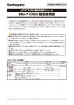
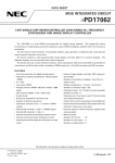
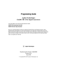
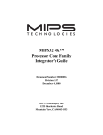
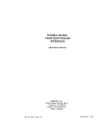
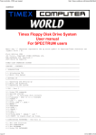
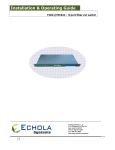
PIO-96
96 Channel Programmable
Input/Output Board
User Manual
PIO-96
User Manual
Document Part N°
Document Reference
Document Issue Level
0127-1015
0127-1015.Doc
1.2
Manual covers PCBs identified
PIO-96 Rev B
All rights reserved. No part of this publication may be reproduced, stored in any retrieval system, or
transmitted, in any form or by any means, electronic, mechanical, photocopied, recorded or otherwise,
without the prior permission, in writing, from the publisher. For permission in the UK contact Blue Chip
Technology.
Information offered in this manual is correct at the time of printing. Blue Chip Technology accepts no
responsibility for any inaccuracies. This information is subject to change without notice.
All trademarks and registered names acknowledged.
Blue Chip Technology Ltd.
Chowley Oak, Tattenhall
Chester, Cheshire
CH3 9EX.
Telephone : 01829 772000 Facsimile : 01829 772001.
Amendment History
Issue
Level
1.1
1.2
Issue
Date
Author
24.11.97
SEJ
Amendment Details
First draft
Window front cover and logo. See ECN
98/088
Contents
1.0 INTRODUCTION.......................................................................... 1
ELECTROMAGNETIC COMPATIBILITY (EMC)................................. 2
EMC Specification ......................................................................... 3
2.0 USER ADJUSTMENTS ................................................................ 4
2.1 Selecting the Base Address (JP1) ............................................ 4
2.2 Setting the Interrupt Channel (JP2) .......................................... 6
3.0 PORT MAP .................................................................................. 7
3.1 Control Port Bit Functions ........................................................ 8
4.0 ELECTRICAL OPTIONS .............................................................. 9
4.1 Input Conditioning .................................................................... 9
4.2 Input/Output Connections......................................................... 9
4.3 Connector Pin Details............................................................. 11
5.0 OPERATING GUIDE.................................................................. 12
5.1 Using the Device.................................................................... 12
5.2 Programming Guide ............................................................... 13
Simple Inputs ............................................................................... 13
Simple Outputs ............................................................................ 13
Typical Register Setups ............................................................... 15
6.0 EXAMPLE PROGRAMS............................................................. 16
Example Program 1 ..................................................................... 16
Example Program 2 ..................................................................... 17
7.0 COMMERCIAL DATA ACQUISITION PACKAGES .................... 20
7.1 Use of the PIO-96 Board with ASYST .................................... 20
APPENDIX....................................................................................... 21
A1 I/O Address Map for PC/XT/AT Computers ............................ 21
A2 Hardware Interrupt Levels for PC/XT ...................................... 22
A3 Hardware Interrupt Levels for PC/AT ...................................... 23
DMA Channels............................................................................. 23
Blue Chip Technology Ltd.
01271015.doc
Introduction
1.0
Page 1
INTRODUCTION
This card provides 96 programmable digital I/O lines. It is suitable for sensing
or driving TTL connections only.
There is provision for a set of on board pull up resistors to enable the board to
be used to detect contact closures on push buttons, relay contacts etc.
This manual refers to printed circuit boards identified (on the rear of the board)
by the reference “PIO-96 Rev. B”.
Whilst every effort has been taken to ensure that the information provided is
accurate, Blue Chip Technology cannot assume responsibility for any errors in
this manual or their consequences. Should any errors be detected, the company
would greatly appreciate being informed of them. A policy of continuous
product development is operated, resulting in the contents of this document
being subject to change without notice.
Blue Chip Technology Ltd.
01271015.doc
Page 1
Page 2
Electromagnetic Compatibility (EMC)
ELECTROMAGNETIC COMPATIBILITY (EMC)
This product meets the requirements of the European EMC Directive
(89/336/EEC) and is eligible to bear the CE mark.
It has been assessed operating in a Blue Chip Technology Icon industrial PC.
However, because the board can be installed in a variety of computers, certain
conditions have to be applied to ensure that the compatibility is maintained. It
meets the requirements for an industrial environment ( Class A product) subject
to those conditions.
• The board must be installed in a computer system which provides screening
suitable for the industrial environment.
• Any recommendations made by the computer system manufacturer/supplier
must be complied with regarding earthing and the installation of boards.
• The board must be installed with the backplate securely screwed to the
chassis of the computer to ensure good metal-to-metal (i.e. earth) contact.
• Most EMC problems are caused by the external cabling to boards. With
analogue boards particular attention must be paid to this aspect. It is
imperative that any external cabling to the board is totally screened, and that
the screen of the cable connects to the metal end bracket of the board and
hence to earth. It is recommended that round screened cables with a braided
wire screen are used in preference to those with a foil screen and drain wire.
Use metal connector shells which connect around the full circumference of
the screen; they are far superior to those which earth the screen by a simple
“pig-tail”. Standard ribbon cable will not be adequate unless it is contained
wholly within the cabinetry housing the industrial PC.
• If difficulty with interference is experienced the cable should also be fitted
with a ferrite clamp as close possible to the connector. The preferred type is
the Chomerics clip-on style, type H8FE-1004-AS.
Page 2
01271015.doc
Blue Chip Technology Ltd.
Electromagnetic Compatibility (EMC)
Page 3
• It is recommended that cables are kept as short as possible, particularly
when dealing with low level signals.
• Ensure that the screen of the external cable is bonded to a good RF earth at
the remote end of the cable.
Failure to observe these recommendations may invalidate the EMC compliance.
Warning
This is a Class A product. In a domestic environment this
product may cause radio interference in which case the user may
be required to take adequate measures.
EMC Specification
A Blue Chip Technology Icon industrial PC fitted with this card meets the
following specification:
Emissions:
EN 55022:1995
Radiated
Conducted
Immunity:
Class A
Class A & B
EN 50082-1:1992 incorporating
Electrostatic Discharge
IEC 801-2:1984
Performance Criteria B
Radio Frequency Susceptibility
IEC 801-3:1984
Performance Criteria A
Fast Burst Transients
IEC 801-4:1988
Performance Criteria B
Blue Chip Technology Ltd.
01271015.doc
Page 3
Page 4
User Adjustments
2.0
USER ADJUSTMENTS
2.1
Selecting the Base Address (JP1)
The board may be located in any 62 pin ISA slot in the PC motherboard, but
must be set up to appear at a specified position (or ‘address’) in the computer’s
port map.
Available positions are shown in the IBM-PC Technical Reference Guide.
However, for those who do not possess a copy of this document a good place is
the location normally allocated to the prototyping card as supplied by IBM.
This address is 300 (hex) or 768 (decimal). All Blue Chip Technology cards
are preset to this address at the factory.
However, no two devices should be used while set to the same address since
contention will occur and neither board will work. If your machine contains a
card with a conflicting address then another reasonably safe address is 200 to
21F (hex).
A set of links on the board set the base address of the board within the IBM-PC
port map. The address is in binary with the presence of a link representing a 0
and the absence of a link representing a 1.
Page 4
01271015.doc
Blue Chip Technology Ltd.
User Adjustments
Page 5
To set the base address to 300 hex (768 decimal) set the pattern on the links as
indicated below:
JP1
10H
20H
40H
80H
100H
200H
Figure 1 - Selecting the Base Address
More example addresses are shown in Appendix A.
Note: No Two cards must occupy the same address.
Blue Chip Technology Ltd.
01271015.doc
Page 5
Page 6
2.2
User Adjustments
Setting the Interrupt Channel (JP2)
The PIO-96 card supports the use of the interrupts generated from the
µPD71055 chips. These chips are identical functionally to the Intel 8255
integrated circuit. The use of the interrupts provides a means to monitor digital
inputs only when there has been a change at the input signal lines. The use of
interrupts requires the user to write an interrupt handler routine (either in C or
assembler) and install it prior to using the PIO-96 card.
To select an interrupt channel, a link must be set on jumper block JP2. An
interrupt is selected by placing a jumper link on the pair of link pins
corresponding to the desired interrupt channel. All other interrupt channel
links must be left open.
Note: Only one link is permitted on JP2. If more than one link is fitted then
the computer system may not function correctly.
Figure 2 - Setting the Interrupt Channel
The above diagram shows the jumper block JP2 with a link placed on interrupt
channel 3. Please note that the silk screen printing of the interrupt numbers on
the printed circuit board is incorrect. The diagram above shows the correct
sequence.
Page 6
01271015.doc
Blue Chip Technology Ltd.
Port Map
3.0
Page 7
PORT MAP
The PIO-96 has four µPD71055 (8255) chips. Each chip has three 8 bit ports
(A, B & C) which can be programmed as inputs or outputs by writing a control
word to the control port. (See Table 2). All “A” ports and “B” ports much each
be all input or all output, i.e. they should not be programmed to mixed input
and output bits within an individual port. Port C may be split into two 4 bit
sections each of which may be input or output. The board occupies sixteen
read/write addresses (four for each µPD71055 chip) in the IBM-PC port map.
ADDRESS
Base + 0
Base + 1
Base + 2
Base + 3
Base + 4
Base + 5
Base + 6
Base + 7
Base + 8
Base + 9
Base + 10
Base + 11
Base + 12
Base + 13
Base + 14
Base + 15
PORT
Port A
Port B
Port C
Command Port 1
Port A’
Port B’
Port C’
Command Port 2
Port A’’
Port B’’
Port C’’
Command Port 3
Port A’’’
Port B’’’
Port C’’’
Command Port 4
Table 1 - Port Addresses
Blue Chip Technology Ltd.
01271015.doc
Page 7
Page 8
Port Map
The function and operation of each of the input/output ports (A, B & C) are
controlled by the control byte which is written to the appropriate Command
Port. Each bit within the byte has a specific function, shown in Table 2.
3.1
Control Port Bit Functions
BIT NO
7
FUNCTION
Mode Set Flag
5, 6
4
Mode Selection
Port A
3
Port C (Upper)
2
Mode Selection
1
Port B
0
Port C (Lower)
SETTINGS
0=Inactive
1=Active
00=Mode 0
01=Mode 1
0=Output
1=Input
0=Output
1=Input
0=Mode 0
1=Mode 1
0=Output
1=Input
0=Output
1=Input
Table 2 - Control Port - Bit Functions
The software described in section 5 the Operating Guide gives examples of the
more typical control bytes and their effects.
Page 8
01271015.doc
Blue Chip Technology Ltd.
Electrical Options
4.0
ELECTRICAL OPTIONS
4.1
Input Conditioning
Page 9
The 71055 has high impedance inputs. An option is provided to terminate
external input lines. This is useful in an electrically noisy environment or
where a load is required (e.g. open collector drive). The lines may be pulled up
to the on-board +5V supply using 12 off SIL resistor packs (identified on the
PCB as “RP1” to “RP6” and “RP11” to “RP16” inclusive). The recommended
values of each resistor to 10Kohm.
4.2
Input/Output Connections
Two 50 way insulation displacement connectors (IDC) are provided for I/O
channel signal connection. One connector is located on the rear bracket and
carries signals 1 to 48. The second connector is located on the board and
carries signals 49 to 96. This connector may be brought out to the rear of the
computer via an adapter cable. If access to individual channels is required, a 50
way IDC ribbon cable may be used to connect the I/O channels to a 50 way
screw terminal block available from Blue Chip Technology as part number
ST-24.
The pins are numbered as shown in the following diagram. Pins 1-48 contain
the I/O signal lines and pins 49 and 50 are connected to digital ground. Both
connectors are identical in their pin-out.
Blue Chip Technology Ltd.
01271015.doc
Page 9
Page 10
Electrical Options
When the connector is viewed from the back of the system odd numbered pins
are on the left and even numbered pins are on the right with pin 1 at the top of
the connector.
Figure 3 - Connector Pin Details (P1 and P2)
(View with gold edge connector facing downwards.)
Page 10
01271015.doc
Blue Chip Technology Ltd.
Electrical Options
4.3
Page 11
Connector Pin Details
PORT
A (1)
B (1)
C (1)
BIT NO.
0
1
2
3
4
5
6
7
0
1
2
3
4
5
6
7
0
1
2
3
4
5
6
7
Digital Ground
PIN NO.
1
3
5
7
9
11
13
15
17
19
21
23
25
27
29
31
33
35
37
39
41
43
45
47
49
PIN NO.
2
4
6
8
10
12
14
16
18
20
22
24
26
28
30
32
34
36
38
40
42
44
46
48
50
BIT NO.
0
1
2
3
4
5
6
7
0
1
2
3
4
5
6
7
0
1
2
3
4
5
6
7
Digital Ground
PORT
A (2)
B (2)
C (2)
Table 3 - Signal Pin Connection Details
(Pin out of both connectors is identical)
Blue Chip Technology Ltd.
01271015.doc
Page 11
Page 12
Operating Guide
5.0
OPERATING GUIDE
5.1
Using the Device
A total of 24 I/O channel signals from each 71055 I/O device on the PIO-96
board provides twelve 8-bit ports. Each signal is connected to one bit within one
of these ports i.e.
Page 12
01271015.doc
Blue Chip Technology Ltd.
Operating Guide
5.2
Page 13
Programming Guide
Simple Inputs
The state of the input lines may be determined by using either of the following
methods:
Microsoft BASIC A or GW BASIC.
X=INP (P)
Returns the byte from port P and assigns this value to the variable X.
8088/8086 Assembly language.
PORT EQU 0300H
GETDAT:
MOV DX,PORT
IN AL,DX
RET
Simple Outputs
The state of the output lines may be modified by using either of the following
methods:
Microsoft BASIC A or GW BASIC.
OUT P,D
Outputs the byte D to Port P
Blue Chip Technology Ltd.
01271015.doc
Page 13
Page 14
Operating Guide
8088/8086 Assembly language
PORT EQU 0300H
PUTDAT:
MOV DX,PORT
MOV AX,DATA
OUT DX,AL
RET
The µPD71055 can operate in one of 3 modes (mode 0, 1 & 2).
In the first mode (mode 0) the µPD71055 provides simple I/O for three 8 bit
ports. Data is simply written to, or read from a specified port (A, B or C)
without the use of handshaking.
Mode 1 enables the transfer of data to or from a specified 8 bit port (A or B) in
conjunction with strobes or handshaking signals provided by Port C.
In mode 2 data is transferred via one bi-directional 8 bit port (A) with
handshakes (Port C).
Page 14
01271015.doc
Blue Chip Technology Ltd.
Operating Guide
Page 15
The following table gives a summary of the most commonly used ‘control
words’ which must be written to each control port to configure the µPD71055s
before using this module. The table assumes mode 0.
Typical Register Setups
Control
Word
(hex.)
80
81
82
83
88
89
8A
8B
90
91
92
93
98
99
9A
9B
Control
Word
(Dec.)
128
129
130
131
136
137
138
139
144
145
146
147
152
153
154
155
Sets All
of
Port B As
Output
Output
Output
Output
Output
Output
Output
Output
Input
Input
Input
Input
Input
Input
Input
Input
Sets High
4 Bits of
Port B As
Output
Output
Input
Input
Output
Output
Input
Input
Output
Output
Input
Input
Output
Output
Input
Input
Sets High
4 Bits of
Port C As
Output
Output
Output
Output
Input
Input
Input
Input
Output
Output
Output
Output
Input
Input
Input
Input
Sets Low
4 Bits of
Port C As
Output
Input
Output
Input
Output
Input
Output
Input
Output
Input
Output
Input
Output
Input
Output
Input
Table 4 - Simple I/O Control Words
For a full explanation of the various modes of operating, and the use of the
signal lines consult the Intel 8255 or NEC µPD71055 datasheet.
Blue Chip Technology Ltd.
01271015.doc
Page 15
Page 16
6.0
Example Programs
EXAMPLE PROGRAMS
Example Program 1
The following program in Microsoft Basic will test the operation of the PIO-96
if a link is made between corresponding pins on the rear of the connector.
10 P1=&H300 : REM BASE OF FIRST PIA
15 P2 = &H304 : REM BASE OF SECOND PIA
20 GOSUB 60
30 P1 = &H304 : P2 = &H300
40 GOSUB 60
50 GOTO 10 : REM LOOP CONTINUOUSLY
60 OUT P1+3, &H80 : OUT P2+3, &H9B
70 FOR P = 0 TO 2
80 F = 0
90 A = 1
100 OUT P1+P,A
110 IF INP(P2+P)<>A THEN PRINT “ERROR”, P,A,INP(P2+P):F=F+1
120 A=A+A
130 IF A=256 THEN GOTO 150
140 GOTO 100
150 IF F>0 THEN PRINT P, “FAILED”, F:GOTO 170
160 PRINT P,”PASSED”
170 NEXT P
180 RETURN
The program runs continuously and can only be stopped by pressing
Control-Break on the PC keyboard.
Page 16
01271015.doc
Blue Chip Technology Ltd.
Example Programs
Page 17
Example Program 2
This example program shows the use of interrupts generated from the
µPD71055 PIO chip. The program sets mode 1 operation which allows data to
be strobed into Port 0 of the first µPD71055 via a LOW signal on Port 2 bit 4.
To determine when data has been strobed into the data port, this example polls
the µPD71055 port 2 register which in mode 1 acts as a control/status register.
In normal use an interrupt handler routine written in C or assembler would be
resident in memory to respond to the hardware interrupt generated by the PIO
card.
NOTES:
• Prior to using interrupts, an interrupt routine must be installed in memory by
the application software.
• To use interrupts ALL unused “INT0” and “INT1” lines (bits 0 and 3 of
each µPD71055 port 2) must be LOW. This means that if a µPD71055 has
been set to (say) mode 0 with all ports as output then Port 2 output lines 0
and 3 must be written to a zero (LOW) state.
• If the ports were set to inputs then interrupts will only occur if Port 2 input
lines 0 and 3 are LOW for each µPD71055 not being used in an interrupt
mode.
• The above is necessary because each µPD71055 “INT0” and “INT1” lines
are logically OR-ed together.
Blue Chip Technology Ltd.
01271015.doc
Page 17
Page 18
Example Programs
CLS
bseaddr% = &H300
port0A% = bseaddr% + 0
port1A% = bseaddr% + 1
port2A% = bseaddr% + 2
ctrlprtA% = bseaddr% + 3
port0B% = bseaddr% + 4
port1B% = bseaddr% + 5
port2B% = bseaddr% + 6
ctrlprtB% = bseaddr% + 7
port0C% = bseaddr% + 8
port1C% = bseaddr% + 9
port2C% = bseaddr% + 10
ctrlprtC% = bseaddr% + 11
port0D% = bseaddr% + 12
port1D% = bseaddr% + 13
port2D% = bseaddr% + 14
ctrlprtD% = bseaddr% + 15
REM set µPD71055 No 2, 3 and 4 to mode 0 - all ports = outputs
OUT ctrlprtB%, &H80
OUT ctrlprtC%, &H80
OUT ctrlprtD%, &H80
REM set all ports for µPD71055 Nos 2, 3 and 4 to LOW
OUT port0B%, 0
OUT port1B%, 0
OUT port2B%, 0
OUT port0C%, 0
OUT port1C%, 0
OUT port2C%, 0
OUT port0D%, 0
OUT port1D%, 0
OUT port2D%, 0
Page 18
01271015.doc
Blue Chip Technology Ltd.
Example Programs
Page 19
REM set mode 1 for normal operation for µPD71055 No 1
REM port 0 = input
REM port 1 = input
REM bits 7 and 6 of port C = input
REM groups 0 and 1 set to mode 1
OUT ctrlprtA%, &HB0
REM set bit manipulation mode to set up µPD71055 chip No 1
REM and set bit 4 high to enable INT0
OUT ctrlprtA%, &H9
LOCATE 1, 1: PRINT "Port 0 of µPD71055 No1"
rdval:
REM get port data before interrupt
dt% = INP(port0A%)
pol:
REM read input buffer full status (bit 5) for µPD71055 No 1
REM this determines when the data strobe has occurred
irq% = (INP(port2A%) AND 32)
IF irq% = 0 THEN GOTO pol
LOCATE 3, 1: PRINT "Before Interrupt"; dt%
rddat:
REM read data from port 0
dta% = INP(port0A%)
LOCATE 4, 1: PRINT "After Interrupt"; dta%
SLEEP (1)
GOTO rdval
Blue Chip Technology Ltd.
01271015.doc
Page 19
Page 20
7.0
Commercial Data Acquisition Packages
COMMERCIAL DATA ACQUISITION PACKAGES
The Blue Chip Technology PIO-96 can be used with almost any data acquisition
package that can read information directly from a PC input port.
7.1
Use of the PIO-96 Board with ASYST
The board has been tested with and is installable as an 71055.PORT digital
device in the ASYST scientific software package by Macmillan Software
Company.
For more details about this package and other PC data acquisition software,
please contact Blue Chip Technology.
Page 20
01271015.doc
Blue Chip Technology Ltd.
Appendices
Page 21
APPENDIX
A1 I/O Address Map for PC/XT/AT Computers
Address
(Hex)
000-01F
020-03F
040-05F
060-06F
070-07F
080-09F
0A0-0BF
0F0
0F1
0F8-0FF
1F0-1F8
200-207
278-27F
2F8-2FF
300-31F
360-36F
378-37F
380-38F
3A0-3AF
3B0-3BF
3C0-3CF
3D0-3DF
3F0-3F7
3F8-3FF
Allocated to
DMA Controller 1, 8237A-5
Interrupt Controller 1, 8259A
Timer, 8254
Keyboard Controller 8742; Control Port B
RTC And CMOS RAM, NMI Mask (Write)
DMA Page Register (Memory Mapper)
Interrupt Controller 2, 8259
Clear NPX (80287) Busy
Reset NPX, 80287
Numeric Processor Extension, 80287
Hard Disk Drive Controller
Reserved
Reserved For Parallel Printer Port 2
Reserved For Serial Port 2
Reserved
Reserved
Parallel Printer Port 1
Reserved For SDLC Comms, Bisynch 2
Reserved For Bisynch 1
Reserved
Reserved
Display Controller
Diskette Drive Controller
Serial Port 1
Blue Chip Technology Ltd.
01271015.doc
Page 21
Page 22
A2
Appendices
Hardware Interrupt Levels for PC/XT
Address
(Hex)
0
1
2
3
4
5
6
7
Page 22
Allocated to
Timer
Keyboard
Reserved
Asynchronous Communications
(Secondary) SDLC Communications
Asynchronous Communications
(Primary) SDLC Communications
Fixed Disk
Diskette
Parallel Printer
01271015.doc
Blue Chip Technology Ltd.
Appendices
A3
Page 23
Hardware Interrupt Levels for PC/AT
Address
(Hex)
0
1
2
Timer Output 0
Keyboard(Output Buffer Full)
Interrupt From Controller 2:8
9
10
11
12
13
14
15
3
4
5
6
7
Allocated to
Real Time Clock Interrupt
Software Redirected To INT(0AH) IRQ2
Reserved
Reserved
Reserved
Co-Processor
Fixed Disk Controller
Reserved
Serial Port 2
Serial Port 1
Parallel Port 2
Diskette Controller
Parallel Port 1
DMA Channels
1
2
3
Floppy Disk Drive. (may be used when disk inactive)
Hard Disk Drive
Spare
Blue Chip Technology Ltd.
01271015.doc
Page 23