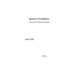
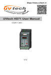
1
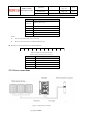
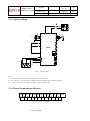
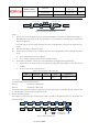
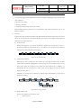
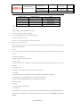
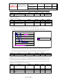
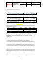
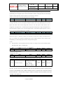
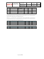
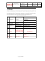
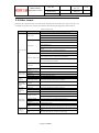
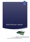
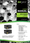
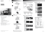
Foreword Thanks for your choosing HD300 solar pump inverter from HEDY company. HD300 special pump inverter is developed for the supply of PV water pumps based on HD700, which has the maximum power tracking ability, dormant at weak light, wake up at strong light, high water level dormant, underload pre-warning and other control protection functions can ensure normal operation of water pumps according to the customers‟ requirements to switch to grid power supply . When commissioning this product, please refer to this manual. For more information, please refer HD700 user manual. Copyright © 2011 by Guangzhou HEDY Intelligent Equipment Co., Ltd. All rights reserved. Please read the information carefully, and keep the manual, please make sure that the end customer has the manual. Warnings, Cautions and Notes Warning: A Warning contains information, which is essential for avoiding a safety hazard. Caution: A Caution contains information, which is necessary for avoiding a risk of damage to the product or other equipment. A Note contains information, which helps to ensure correct operation of the product. WARNING The HD300 Solar pump inverter should ONLY be installed by a qualified electrician. Install the inverter far away from the inflaming materials like metal sheet in case of fire. Do not install the inverter in environment with explosive gas. Even when the motor is stopped, dangerous voltage is present at the Power Circuit terminals L1, L2, L3 and U, V, W and, depending on the frame size, DC+ and DC−, or BR. Dangerous voltage is present when input power supply is connected to the inverter. After disconnecting the supply, wait at least 10 minutes (to let the intermediate circuit capacitors discharge) before removing the cover. PE terminals must be earthed very well. CAUTION The HD300 is not a field repairable unit. Never attempt to repair a malfunctioning unit; contact the factory or your local Authorized Service Center for replacement. The HD300 will start up automatically after an input voltage interruption if the external run command is on. Prior to measurements on the motor or the motor cable, disconnect the motor cable from the solar inverter. Before connecting the solar pump inverter to mains, make sure that the HD300‟s front and cable covers are closed. 1 Technical specification 1.1 Model reference HD300 - 4 0 T 00550 Non: Standard G type E: small size G type P: small size P type Family Supply voltage 2:220V 4:380V Power size 00075:0.75kW | 01500:15KW Brake unit 0:Internal fitted 1:Non Input phase T:3PH Figure1-1 HD300 model description 1.2 Rating Label Industrial Automation Control Model: HD300-40T00220 Power: 2.2kW/3.8kVA Input: 3PH 380VAC~480VAC 48Hz~62Hz 8.3A Output: 3PH 0V~Input 0Hz~300Hz 5.8A S . N. : XXXXXXXXXX E348255 Made in China Figure1-2 HD300 Rating label 1.3 Power degree Power size of HD300 refers to the standard 4 poles induction motor at rated voltage. Overload:150% rated output current, 1 minute Table 1-1 380V rating data Inverter model HD300-40T00075 Max DC current (A) 4.2 input Rated output current (A) 2.5 Applicable water pump (KW) HD300-40T00150 6.1 3.7 1.5 HD300-40T00220 7.1 5 2.2 HD300-40T00400 16.5 9.5 4 HD300-40T00550 23.9 14 5.5 HD300-40T00750 30.6 18.5 7.5 HD300-40T01100 39.2 25 11 HD300-40T01500 49.0 32 15 0.75 Noted: when the output voltage is 380V, the output current will be rated value; when the output voltage is 400V,/415 V or 440V,the output current will be calculated according to power Table 1-2 220V rating data Inverter model HD300-20T00075 Max DC current (A) 6.7 input Rated output current (A) 4.5 Applicable water pump (KW) HD300-20T00150 9.9 7 1.5 HD300-20T00220 14.1 10 2.2 HD300-20T00400 22.6 16 4 HD300-40T01500 49.0 32 15 0.75 Noted: when the output voltage is 220V, the output current will be rated value 1.4 Electrical Specifications Table 1-3 Electrical Specifications 220v 380v Max input DC voltage 410v 800V Recommended MPPT voltage range 270~400VDC 350~750VDC Recommended input voltage 310V 513V MPPT efficiency 99.9% Input channel 1 Rated output voltage 3-phase 220VAC Output frequency range 0~60Hz Max efficiency of the machine 97% Ambient temperature range -10 °C~50 °C, derating if the temperature is above 40 °C Cooling method Air cooling Protection degree IP20 Altitude Below 1000m; above 1% for every additional 100m. Standard CE 3-phase 380VAC 1.5 Recommended solar array configuration Table 1-4 recommended solar array configuration Open-circuit voltage degree of solar module 20±3V Max DC input Modul current Module e (A) Power Per ±5Wp string *string 30±3V HD300-20T00075 6.7 50 16*1 - Modu le Module Module Module Module Module Module Module Module Per Per Per Per Per Power Power Power Power string string string string string ±5Wp ±5Wp ±5Wp ±5Wp *strin *string *string *string *string g - HD300-20T00150 9.9 110 16*1 165 11*1 - - - - - - - - HD300-20T00220 14.1 - - 120 11*2 150 9*2 - - 330 8*1 - - HD300-20T00400 22.6 - - 220 11*2 135 9*4 - - 300 8*2 - - HD300-40T00075 4.2 30 29*1 - - - - - - - - - - HD300-40T00150 6.1 60 30*1 - - - - - - - - - - HD300-40T00220 7.1 90 30*1 - - 145 18*1 - - 175 15*1 - - HD300-40T00400 16.5 85 28*2 220 22*1 140 17*2 - - 160 15*2 - - HD300-40T00550 23.9 - - - - 195 17*2 - - 220 15*2 - - HD300-40T00750 30.6 - - 215 21*2 175 17*3 - - 200 15*3 300 15*2 HD300-40T01100 39.2 - - 200 22*3 195 17*4 - - 220 15*3 - - HD300-40T01500 49 - - 205 22*4 175 17*6 200 18*5 240 15*5 300 15*4 Inverter model Module Power ±5Wp 36±3V 42±3V 2 Installation and cabling 2.1 Dimension 2.1.1 Parts of drive Keypad Barcode Keypad Connector RS485 Port Terminal Cover Control Terminals Option Connector Rating Label EMC filterLink Power Terminals Fan Figure 2-1 Parts of HD300 drive 2.1.2 Diagram of mounting W W1 D H H1 Ø Ø Figure 2-2 Mechanical dimensions and mounting (SizeA, B, C) W W1 Ø D H H1 W2 Ø Figure 2-3Mechanical dimensions and mounting (Size D) Table 2-1 Mechanical dimensions Size Model Name W W1 W2 H H1 D D1 Mounting Weight (mm) (mm) (mm) (mm) (mm) (mm) (mm) Hole Ø (kg) HD300-20D00075 HD300-20D00150 A HD300-40T00075 97.4 80 202.4 190 148.8 5 1.4 HD300-40T00150 HD300-20D00220 B HD300-40T00220 142.4 123.5 − 220.4 208 155.5 − 5 2.2 163.1 142 − 300 280 176.8 − 6 4.5 238.5 184 92 370 356.5 189 − 7 8.8 HD300-40T00400 HD300-20D00400 C HD300-40T00550 HD300-40T00750 HD300-40T01100 D HD300-40T01500 2.2 Mechanical installation 2.2.1 Drive installation diagram H L L H Figure 2-4 ingle drive installation Recommending: L≥50mm, H≥50mm L L L Figure 2-5 Multi-drives installation Recommending: L≥50mm NOTE :In vertical installations where drives are mounted above each other, there should be suitable air flow to keep the drives cool. Air flow should be drawn in and expelled as illustrated in the left picture. Figure 2-6 Multi drives vertical installation 2.2.2 Fit and remove the terminal cover Clips C ES A O Hz PR RU N O ST P D MO DE MO rol nt OG Co ad yp Ke PR V Remove: Unscrew, loose the clip then take off the cover. Fit: by a suitable angle, put the clips into the slots on the middle cover, push the cover on, tighten Figure 2-7 Terminal cover fitting and removing the screwM4×10 (Torque 1N·m). HEDY Industry Automation Control Doc. No. 文件版本 Doc. Ver V1.0 Secret Level 模板版本 Temp. Ver V1.0 Release Scope 2.2.3 How to fit and remove the keypad Figure 2-8 Diagram of the keypad fitting Remove: push the spring clip, and then pull up the keypad. Fit: fit the left two clips (correct angle) into the slots on the control pod, and then push down the keypad. HD300 keypad is removable, and can be linked to the drive with a standard net cable -,shown as below: port converter Figure 2-9 Keypad cable link NOTE: The maximum length of cable is 10m. 2.3 Electrical installation 2.3.1 Power terminals Models of size A, B, C: HD300-20D00040~HD300-40T00750 L1 L2 L3/N U V PE +DC +DC1 BR −DC W PE Figure 2-10SizeA, B power terminals layout L1 L2 L3 PE +DC U V BR −DC W PE Figure 2- 11SizeC power terminals layout Copyright by HEDY HEDY Industry Automation Control Doc. No. 文件版本 Doc. Ver V1.0 Secret Level 模板版本 Temp. Ver V1.0 Release Scope Table 2- 2Power terminal functions of sizeA, B, C Terminals Functions L1, L2, L3/N AC power supply.For single phase supply,we suggest to use L1, L3/N +DC, +DC1 For DC choke, linked by terminal BR Brake resistor, another end is +DC1 −DC Negative DC bus U, V, W Output terminals(Motor terminals) PE Protective earth terminal NOTE: Size C has DC choke inside, +DC1 is not used. For size C, the brake resistor is connected to BR and +DC. Models of size D: HD300-40T01100~HD300-40T02200 +DC BR −DC L1 L2 L3 PE PE Figure 2-12SizeD, E power terminals layout Table 2- 3Power terminal functions of sizeD, E Terminals Functions L1, L2, L3 AC power supply +DC, −DC Positive and negative DC bus BR Brake resistor, another end is +DC U, V, W Output terminals(Motor terminals) PE Protective earth terminal 2.3.2 Power connections Figure 2- 13Typical power connection Copyright by HEDY U V W HEDY Industry Automation Control Doc. No. 文件版本 Doc. Ver V1.0 Secret Level 模板版本 Temp. Ver V1.0 Release Scope NOTE: The selection of fuse and switch refers to table 2-14. Do not suggest using the power contactor to control the RUN/STOP of the drive. In default carrier frequency, the maximum motor cable length is 100 meters. When the motor cable is longer than 100m, recommend to use output reactor. For safety, drive and motor must be earthed, and the earth contacting resistance must be less than 10Ω, the earthing conductor must meet the requirements in table 2-15. Table 2-4Recommended fuse, power cable and control cable Fuse Model HD300-20D00075 IEC gG (A) 1PH 3PH 16 10 HD300-20D00150 25 HD300-20D00220 32 Power <30A,CC class >30A,T class (A) Input current (A) Supply cable (mm2) Motor cable (mm2) Control cable (mm2) 1PH 3PH 2.5 1.0 3PH 1.0 ≥0.5 1.5 1.0 ≥0.5 2.5 1PH 15 3PH 10 1/3PH 12.8/7.1 16 25 15 20.5/11.3 2.5 20 32 20 24/14.5 4.0 1.5 ≥0.5 HD300-20D00400 20 20 16.5 2.5 2.5 ≥0.5 HD300-40T00075 8 8 3.6 1.0 1.0 ≥0.5 HD300-40T00150 10 10 5.7 1.0 1.0 ≥0.5 HD300-40T00220 16 15 8.3 1.5 1.0 ≥0.5 HD300-40T00400 20 20 13.2 2.5 1.5 ≥0.5 HD300-40T00550 20 20 12.4 2.5 2.5 ≥0.5 HD300-40T00750 25 25 16.1 2.5 2.5 ≥0.5 HD300-40T01100 40 40 31 4.0 4.0 ≥0.5 HD300-40T01500 50 45 36 6.0 6.0 ≥0.5 Table2- 5Earth conductor cross sectional area Power cable cross sectional area-S (mm2) Earth conductor cross sectional area-Sp (mm2) S≤16 S 16<S≤35 16 35<S S/2 NOTE: The data in the table2-12 is base on that they are same metal material; otherwise the area value should be modified by the conductor factor between the different metal material. Copyright by HEDY HEDY Industry Automation Control Doc. No. 文件版本 Doc. Ver V1.0 Secret Level 模板版本 Temp. Ver V1.0 Release Scope 2.3.3 Typical cabling Q2 PV modules Q1 The grid −DC +DC Motor L1 L1 U L2 L2 V L3 L3/N W PE PE PE Run/Stop M AO1 DI1 0V DI2 DO1 Programmable DI3 MPPT Voltage reference DO2 DI4 DI5 HD300 0V 24V DI6 RL1 DI7 Common RL2 0V RL3 RL4 CN3 0V 0V~10V 0V~10V/0(4)mA~20mA Full water level AI2 AI1 10V CN2 A B RJ45 port Less water level Reservoir Figure 2- 14Typical cabling NOTE: All the programmable control terminal functions are factory default set. For control wire, recommend using unshielded twisted pair, shielded cable or shielded twisted pair. 5.5kW~15kW models (including 220V/4kW), internal DC Choke is fitted. 2.3.4Control terminals specification RL3 RL4 0V AI2 24V DO2 DI4 DI5 DI6 DI7 A B RS485 RL1 RL2 0V AI1 10V AO1 DO1 24V 0V DI1 DI2 DI3 Figure 2-15Control terminal diagram Copyright by HEDY HEDY Industry Automation Control Doc. No. 文件版本 Doc. Ver V1.0 Secret Level 模板版本 Temp. Ver V1.0 Release Scope Table 2-6 Control terminal andcomms.port Type Terminal Name comms. Technical Specifications RJ45port Two lines, Modbus RTU protocol A 485 plus signal Same function with RJ45 port, mainly for multi network B 485 minus signal RS485 Serial Function DI1~DI5 DI6 The common can be 0V or 24V by setting the P09.21(default is 0V) Programmable digital Input resistance: 10 kΩ input terminals High, low logic threshold:10V±1V Sample time: 1ms Normal digital input Length counting Number counting Digitalinp ut Length counting by input pulse Sample time: 5ms Number counting by input pulse Sample time: 5ms Note: pulse frequency range is 0Hz~60Hz. Same as DI1~DI5, but Input resistance is 5kΩ High frequency pulse input Frequency range: 1kHz~50kHz DI7 Normal digital input High frequency pulse input Motor thermister input DO1 Output: 24V/0V Programmable digital Max. output current: 50mA output terminal1 Updating rate: 20ms DO2 Programmable digital output terminal1 Digital output AI1 Programmable analogue input1 Analogue input and output Rail supply and Relay Same as DI1~DI5 AI2 Programmable analogue input1 AO1 Programmable analogue output 10V Analogue reference rail Copyright by HEDY Only when P09.21=1 input can be thermister Trip resistance: 3kΩ Reset resistance: 1.8kΩ Sample time: 5ms same with DO1 High frequency pulse output(0.1kHz to 50kHz) PWM output(10kHz) 0V~10V Input resistance: 100k 0 (4) mA~20mA Load resistance:188 Min. Potentiometer resistance: 0.5k Resolution: 0.1% Accuracy: 2% Sampling period: 5ms 0V~10V Input resistance: 30k Min. Potentiometer resistance: 0.5k Resolution: 0.1% Accuracy: 2% Sampling period: 5ms 0V~10V Max. output current: 5mA Resolution: 0.4% Accuracy:±5% Updating rate: 5ms Accuracy: 2% Max. output current: 20mA HEDY Industry Automation Control Doc. No. 文件版本 Doc. Ver V1.0 Secret Level 模板版本 Temp. Ver V1.0 Release Scope Terminal Name Type 24V User supply (2) 0V Common (3) RL1,RL2 Rail supply and Relay Function RL3,RL4 Technical Specifications Accuracy: ±15% Maximum output current: 100mA Common reference point for control signal Type: normal open Programmable relay1 Updating rate: 5ms output contactors Contactor rating: 250VAC/2A(cosφ=1) 250VAC/1A(cosφ=0.4) Programmable relay2 30VDC/1A Default: output contactors Relay1: closed when powered and healthy. Relay2: closed when drive is active. Digital input terminal basic function There are 7 programmable digital input terminals. P09.01=0(default), only basic function for digital input P09.01=1, advanced functions are available for digital input. This manual only introduces the basic function of digital input. The basic function list is as the following table: Table 2-7 HD700 digital input basic function list Terminal Parameter DI1 P09.02 Range Default 0: Preset select bit0 1: Preset select bit1 3 2: Run DI2 P09.03 3: Run forward 4 4: Run reverse 5: 3-wire enable DI3 P09.04 6: FWD/REV 7 7: Jog forward DI4 P09.05 8: E Pot (UP) 0 9: E Pot (DOWN) 10: Enable DI5 P09.06 DI6 P09.07 DI7 P09.08 11: Reset 1 12: Switch to terminal control 13: Reset of length counting 16:Preset select bit2 17:Preset select bit3 18:PLC reset indicator 19: No function 99: Advanced function Copyright by HEDY 10 11 HEDY Industry Automation Control Doc. No. 文件版本 Doc. Ver V1.0 Secret Level 模板版本 Temp. Ver V1.0 Release Scope 3 Operation and display 3.1 Keypad There are a 5-digit LED display of 8 segment, 3 unit lights, and a RUN light on the HD300 drive keypad as shown below: Figure 3-1 LED keypad 3.1.1 LED lights LED display can show the drive status, parameters and value, trip, warning information, etc. Run light is on the upper right corner of the switch of , when drive is active, the light is on. Table 3-1Unit light Unit Function Color Hz On: output frequency Flash: Reference frequency Green A On: Output current Green V On: Output voltage(RMS) Flash: DC bus voltage Green Copyright by HEDY HEDY Industry Automation Control Doc. No. 文件版本 Doc. Ver V1.0 Secret Level 模板版本 Temp. Ver V1.0 Release Scope 3.1.2 Key function Table 3-2Switch function Switches Function Description In different level display, press the switch will return the last level; long press on the switch, will display the value of normal display parameter decided byP05.01. When the keypad is locked, 5 seconds pressing on the switch will unlock. Programmable switch, it can be function of Jog, Fwd./Rev., Coasting stop by settingP05.07. Default function is Jog. Enter next level of the keypad display. When it is keypad control mode (P00.03or P10.07=0), press the switch will make the drive run. Stop, the switch will stop the drive unless the keypad is locked totally. Reset the drive if the keypad is not locked totally. Are used to select parameters and edit their values. In keypad mode, they are used to increase and decrease the speed of the motor. Under Run/Stop mode, press the switch the LED display will be output frequency, reference frequency, output current, output voltage, DC bus voltage in turn Under the edit of parameter value mode, press the switch will change the bite of the value. NOTE: If there is a conflict on the content of parameter, pressing “PRG” switch cannot enter the next parameter. Copyright by HEDY HEDY Industry Automation Control Doc. No. 文件版本 Doc. Ver V1.0 Secret Level 模板版本 Temp. Ver V1.0 Release Scope 3.1.3 Keypad operation Keypad can control the running of the drive, or monitor the status of the drive, details as below: LED Display If P05.02 is set to 0 Normal display is the value of the parameter which is selected by the P05.01; default is output frequency(value of P05.11). HD300 has a quick display group, switchover value is: output frequency, reference frequency, output current, output voltage, DC bus voltage. Operation procedure is as figure 3-2: Output frequency Reference frequency Output current 0.00 0.00 Output voltage 0 0.0 DC bus voltage 537 Figure3-2 Display switchover flow If P05.02 is set to 1 On standby mode, normal display is reference frequency. Operation procedure is as figure 3-3: Reference frequency Output frequency 0.00 0.00 Output current Output voltage 0.0 0 DC bus voltage 537 Figure 3-3Display switchover flow In running mode, normal display is output frequency. Operation procedure is as figure 3-4: Output frequency Reference frequency Output current 0.00 0.00 Output voltage 0.0 0 DC bus voltage 537 Figure 3-4Display switchover flow NOTE: Normal display can be the value of any parameter selected by P05.01. For example, if set P05.01=5.08, then the normal LED display will be motor speed. During the switchover process, press the switch of ESC, the LED display will return to the normal display content. The view of the parameter and the edit of parameter value For HD300 family, there are three levels about parameter view and edit. Level1: menu group Level2: parameter Level3: parameter content Operation flow is described in figure3-5: Copyright by HEDY HEDY Industry Automation Control Doc. No. 文件版本 Doc. Ver V1.0 Secret Level 模板版本 Temp. Ver V1.0 Release Scope Change menu group Change parameter P00 0.00 Change parameter value P00.01 0 P00.02 Left shift parameters Default display Figure 3-5parameter view and edit flow NOTE: In level3, user can turn the display to level2 by pressing switch PRG or switch ESC, the difference among them is: Press PRG will save the change of the value and return level2 (next parameter), press PRG again, will display the value of next parameter. Press ESC will not save the change and return the level2 (current parameter), ESC again will return the level1 display. Only after press PRG, the change can be active If there‟s no bite of parameter value is flashing, means the value of the parameter cannot be changed, the reasons maybe: It is an actual parameter, cannot be changed Drive is running, and the parameter cannot be changed at running If more than one parameters are being set to same value(function), will happen following phenomena: Keypad set up, the change will not be activable after pressing PRG, and the display can not enter the next parameter PC Tools set up, the drive will trip at F021 Table 3-3List of parameters with conflict setup Analogue input Digit input PID output source P08.03, P08.08 P09.02~P09.08 P15.15 Logic output source P16.07, P16.14, P16.19 Threshold and selector output source P17.05, P17.10, P17.17, P17.24, P17.31 For example: The default function of digit input terminal are: P09.02=3 DI1 function is Run forward. P09.03=4 DI2 function is Run reverse. If change the setup of DI2, like setP09.03=3 (DI2 function is forward running also), press PRG, the value of P09.03is still "4", and the Display can not enter the next parameter P09.04. Example of editing parameter The example is to change the value of P04.01 from 5.00Hz to 40.50Hz, as the following figure 3-6. The number with underline is flashing. 0.00 P00 P04 4 times 5.00 P04.01 1 time 1 time 5.50 5.00 5 times 1 time 1 time 0.00 P04 P04.02 40.50 Press Figure 3-6Editing parameter flo Copyright by HEDY 10.50 10.50 4 times 1 time 5.50 5 times key, until display 40.50 HEDY Industry Automation Control Doc. No. 文件版本 Doc. Ver V1.0 Secret Level 模板版本 Temp. Ver V1.0 Release Scope Lock and unlock the keypad To avoid wrong keypad option, HD300 has the function of keypad lock through the setup of P05.06, if the value of P05.06 is: 0: all the keys are activable 1: all the keys are locked 2: except RUN and STOP keys, other keys are locked. Keypad unlocked operation: press ESC over 5 seconds and the value of P05.06 will become to be “0”, the keypad is unlocked. User code To protect the secrets of customer parameter setup, HD300 designs the function of user code. Once the user code is set, if can not enter the correct PIN in the P00.01, the keypad can only display normal display and parameter P10.06, and its value is "0". Set the user code Default value of P00.01 is "0", and user code function is disabled. If set P10.06a non "0" value (1~ 9999) and press PRG once and press ESC twice, it will enable the user code function. The example of setting the user code to 4 showed as below figure 3-7: 0.00 P10 P00 1 time 10 times P10.01 1 time P10.06 5 times 0 1 time 4 times 4 P10.07 1 time P10 1 time 0.00 1 time Figure 3-7User code setting flow Verify the user code(PIN) When the user code is enabling, only after entering the correct PIN into P10.06 and press PRG, customer can view and edit all the parameters. After verifying user code successfully, if there‟s no any action on any switch on the keypad in two minutes, the value ofP10.06 will be changed to "0" automatically, the user code function is enable again, and the keypad will show the normal display(selected by P05.01). If the PIN is "8", and the user code function as on Enable stage, following figure 3-8 shows how to pass the PIN verifying. Authentication successful 0.00 P10 1 time P10.06 1 time 0 1 time 8 8 times 5 5 times Figure 3-8PIN verifying procedure Remove the user code There are two methods to remove the user code: Software remove Copyright by HEDY P00.01 1 time P00 1 time P10.06 1 time Authentication failed HEDY Industry Automation Control Doc. No. 文件版本 Doc. Ver V1.0 Secret Level 模板版本 Temp. Ver V1.0 Release Scope After verifying the PIN successfully, change the content of P10.06 to "0", then press PRG, disable the user code function. Hardware remove During the drive power off process, press the switches of + + at the same time, then loosen the switches after power up. Change the content ofP10.06to "0", disable the user code function. 3.2 Drive control 3.2.1 Drive status HD300 drive status is defined as: Ready (Stop), Running, Editing, , Trip, and Alarming. Stop: After powered up and reset process, if there is no RUN action, the drive will keep the stop status, RUN light is off. Running: The drive is activate, RUN light is on. Editing: Through keypad or PC Tools, program the parameters. Trip:Because of internal fault, external fault or wrong operation, the drive will trip and display relative fault code. Alarm: When drive is under alarm status, keypad will display relative alarm code (Hxxx). The alarm code will keep flashing for 3 seconds and then turn over to the normal display(selected byP05.01). The normal display will flash for 3 seconds then back to flash alarm code, will keep this cycle until the alarm is removed or trip. The parameterP12.13can be set to decide if display the alarm information or not. 3.2.2 Control modes Through P00.03 (P10.07), there are 3 control modes: 0: Keypad 1: Terminal 2: Serial comms. Copyright by HEDY HEDY Industry Automation Control Doc. No. 文件版本 Doc. Ver V1.0 Secret Level 模板版本 Temp. Ver V1.0 Release Scope 4. Parameter 4.1 Property of parameter The following parameter description includes: Parameter ID: code of parameter. Parameter name: simple explanation of the parameter. Parameter range: the range of the parameters content, in 【】is the default value. Change mode: to define if the parameter can be modified, and under what condition can change the parameter. Run&Stop Write &Read can be done at running and stop. Stop Only Write &Read can be done only at stop. Actual Read only 4.2 Parameters list For more parameter description please refer HD700 user manual V1.4. Menu P00 Code P00.01 (P05.02) Name Range Keypad cycle display mode 0~2 Min unit 1 Default 0 Change Run&Stop 0: Fixed mode Keypad cycle display order: on standby or running state, the order of keypad cycle display will not be changed. >> P05.14 >> P01.14 P05.12 ESC ESC >> >> ESC ESC P05.01 P05.13 >> 1: Auto switch mode in running state Keypad cycle display order: the order as shown in the figure below when the drive is on standby; when the drive is running, it will automatically switch to the circular order of fixed mode. >> P05.14 >> P05.01 P05.12 ESC ESC >> >> ESC ESC P01.14 2: Reserved Copyright by HEDY >> P05.13 HEDY Industry Automation Control Doc. No. 文件版本 Doc. Ver V1.0 Secret Level 模板版本 Temp. Ver V1.0 Release Scope Code Name Range Min unit P00.02 (P05.03) Parameter display selection 0~2 1 Default 1 Change Run&Stop 0: Only menu P00 1: All menus 2: Only parameters which have different value with the defaults set Code Name Range Min unit P00.03 (P10.07) Control Mode 0~2【0】 1 Code Name Range Min unit P00.04 (P01.01) Reference source selector 0~8 1 Default 0 Change Stop Only 0: Keypad 1: Terminal 2: Serial comms. Default 0 Change Run&Stop 0: Keypad Through adjusting ▲ or ▼ switches to change the frequency reference, and the Power up value is decided by parameter P00.12 (P01.11). 1: E-Pot Through the two terminals which are defined as UP, DOWN function to change the reference. For example: Define the DI4 and DI5 as UP and DOWN function, and the setup is as below: P09.05=8 DI4 function is UP P09.06=9 DI5 function is DOWN 2: Preset Controlled by terminals, the reference is the value of P04.01 (preset1)~P04.16 (preset16). Use the default setup as an example: P09.05=0 DI4 is preset select bit0 P09.06=1 DI5is preset select bit 1 There are tow operation modes: When the reference source is preset, terminal status as shown below: Table 4-1Preset and preset terminal status corresponding table 1 DI5 Status (bit 1) DI4 Status (bit 0) Speed OFF OFF Preset1 (P04.01) OFF ON Preset2 (P04.02) ON OFF Preset3 (P04.03) ON ON Preset4 (P04.04) When the reference source is not preset, terminal status as shown below: Copyright by HEDY HEDY Industry Automation Control Doc. No. 文件版本 Doc. Ver V1.0 Secret Level 模板版本 Temp. Ver V1.0 Release Scope Table 4-2 Preset and preset terminal status corresponding table 2 DI5 Status (bit 1) DI4 Status (bit 0) Speed OFF OFF Keep the frequency setting OFF ON Preset2 (P04.02) ON OFF Preset3 (P04.03) ON ON Preset4 (P04.04) About 16 presets (P04.01~P04.16) control, please refer to MenuP04. 3: AI1 There are two analogue input terminals:AI1, AI2. In this User manual, only AI1 is introduced. According to parameter P08.03, AI1has three functions: P08.03=0, AI1 is speed reference P08.03=1, AI1 is the speed limit under Torque control mode P08.03=2, AI1is the Torque error About AI1signal mode, there are current mode and voltage mode, details please refer to the explanation of parameter P00.05 (P08.02). 4: AI2 AI2 function is decided by the parameter P08.08, it is same with AI1, and the default function is frequency reference. AI2 has only voltage mode. AI2detail setup please refer to Menu P08 5: Serial comms. Under this mode, user can change the value of P04.01 (Preset1) for the reference. Details please refer to the appendix1. 6: DI7 Pulse input When P09.24=2, DI7 function is reference channel (by input pulse) For example: The maximum frequency of input pulse (P09.27) is 20.0kHz, actual input pulse is 10.0kHz. The percentage of DI7 pulse input (P09.38) is 50.0%. Then the reference is: Reference=DI7 input percentage(P09.38)×maximum reference(P00.07) =50.0%×50.00Hz =25.00Hz 7: Optional card (By option modules) 8: User program By destination and source control, user can define the reference channel freely.For example through Menu P17, user can define the reference source. About actual application guide, please refer to the HD700 Advanced User Manual. Copyright by HEDY HEDY Industry Automation Control Doc. No. 文件版本 Doc. Ver V1.0 Secret Level 模板版本 Temp. Ver V1.0 Release Scope Code Name Range Min unit P00.05 (P08.02) AI1 mode selector 0~6 1 Default 6 Change Stop Only AI1 signal can be voltage or current mode. 0: 0mA~20mA 1: 20mA~0mA 2: 4mA~20mA (current loosing with trip) 3: 20mA~4mA (current loosing with trip) 4: 4 mA~20mA (current loosing without trip) 5: 20mA~4mA (current loosing without trip) 6: 0V~10V When the AI mode selection is“0~5”, if the input current is over26mA, the drive will trip at F012, the drive will stop as the mode decided by P03.10, then turn off the IGBTs. When this parameter is set to 2 or 3, if the input current is less than3mA, then the drive will trip at F013, the drive will stop as the mode decided by P03.10, then turn off the IGBTs. NOTE: If the selection is "2~5", once the current is less than 3mA, P08.16 (current loosing indicator) is 1. Code Name Range Min unit P00.06 (P04.01) Preset1 ±Max. reference 0.01Hz Default 5.00Hz Run&Stop Change Code Name Range Min unit P00.07 (P01.02) Max. reference Min. reference 0.00Hz~300.0Hz 0.00Hz~max. reference 0.00 Hz Default 50.00 Hz Stop Only 0.00 Hz 0.00 Hz Stop Only P00.08 (P01.03) If P03.01=0 (reverse is enabled), then the P00.08 is fixed at 0.00Hz. Copyright by HEDY Change HEDY Industry Automation Control Doc. No. 文件版本 Doc. Ver V1.0 Secret Level 模板版本 Temp. Ver V1.0 Release Scope Code Name Range Min unit P00.09 (P02.04) P00.10 (P02.05) Acceleration rate1 Deceleration rate 1 0.0s~3600.0 0.0s~3600.0 0.1 0.1 Default 10.0 20.0 Change Run&Stop Run&Stop Acceleration rate is the time from 0Hz to maximum reference. Deceleration rate is the time from maximum reference to 0Hz. For example: P00.07 (P01.02) =100.00Hz, set up the maximum reference P00.09 (P02.04) =10.0s After starting, the drive output frequency is from 0.00Hz ramp to 50.00Hz and the acceleration rate is:10.0s× (50.00Hz/100.00Hz) =5.0s Code Name Range Min unit Default Change P00.11 (P03.10) Stop mode 0~3【0】 1 0 Stop mode Code Name Range Min unit Default Change P00.12 (P01.11) Keypad power up reference 0~2 1 0 Run&Stop 0: Ramp stop 1: Coasting 2: Ramp +DC injection 3: Coasting +DC injection When the reference source is keypad, the reference when powered up is decided as below: 0: Starting reference is "0" 1: Starting reference is the output frequency before powered off 2: Starting reference is preset1 (P04.01) Copyright by HEDY HEDY Industry Automation Control Doc. No. 文件版本 Doc. Ver V1.0 Secret Level 模板版本 Temp. Ver V1.0 Release Scope Code P00.13 (P13.06) Name Range Min unit Default Change 1V 200V: 220V 400V: 380V 690V: 660V Stop Only 0.1A By model Stop Only 0.1Hz 1rpm 1 50.00Hz 0rpm 0 Stop Only Stop Only Stop Only 200V: 0V~240V 400V: 0V~480V 690V: 0V~690V Motor1 rated voltage P00.14 (P13.07) Motor1 rated current P00.15 (P13.08) P00.16 (P13.10) P00.17 (P13.02) Motor1 rated frequency Motor1rated RPM Autotune selector G or P type: 0.1A~rated current ×1.2 GP type: 0.1A ~ P type rated current 1.00Hz~300.0Hz 1rpm~60000rpm 0~3 0: No action 1: Static autotune1 (first run) When P00.17=1, press PRG make sure the change and return the ready stage, once there is a run order, the drive will do the static auto-tune, after finished, P00.17=0, and the drive will be at ready status. 2: Static autotune2 (every run) When P0.17=2, every run order received, the drive will do the autotune, after the static autotune, save the result into the EEPROM, and P0.17=2, and the drive is running. 3: Reserved NOTE: If the auto-tune is working without load motor, the drive will trip at F016. Code Name Range Min unit Default Change P00.18 (P13.11) Motor1 stator resistance 0.000~60.000Ω 0.001Ω 0 Stop Only After auto-tune finished, this parameter will be updated. If the resistance value is out of the range, trip F016 will happen. Code Name Range Min unit Default Change P00.19 (P13.05) Motor1power factor 0.00~1.00 0.01 0.85 Stop Only PF and motor rated current (P00.14) are used to calculate the motor torque current and magnetizing current. Code Name Range Min unit Default Change P00.20 (P13.01) Motor voltage control mode 0~2 1 0 Stop Only 0: V/F control 1: Open loop vector control1 2:Open loop vector control 2 Note: To use open loop vector control mode 1 or 2, you need to set up motor parameters correctly (nominal voltage, current, pole pairs, rated speed) and finish auto-tune. Copyright by HEDY HEDY Industry Automation Control Doc. No. 文件版本 Doc. Ver V1.0 Secret Level 模板版本 Temp. Ver V1.0 Release Scope Code Name Range Min unit Default Change P00.21 (P10.10) Switch frequency 1kHz~15kHz 1KHz By model Run&Stop Switch frequency can affect the motor noise and drive power loss, higher switch frequency, lower motor noise but bigger IGBT power loss. Code Name Range Min unit Default Change P00.22 (P06.08) Voltage boost level 0.0%~30.0% 0.1% by mode Run&Stop Output voltage Ve Vb fz fb Output frequency Figure 4-1 Voltage boost Ve: motor rated voltage Vb: Boost voltage=Ve×P00.22 fZ: boost close frequency (P06.09) fb: rated frequency Code Name Range Min unit Default Change P00.23 (P06.01) V/F mode setup 0~3 1 0 Stop Only Different V/F characteristic is defined by P00.23 to meet the demanding from different load. There are three kinds of fixed curve and one user programmed line When P00.23 (P06.01) is 0, user can define the different fold lines by the setting of P06.02~P06.07, add (V1, F1)、 (V2, F2)、 (V3, F3) three points to define the V/F lines mode. The default V/F is a straight line, as the line0 in Figure 4-2. When P00.23 (P06.01) is set to 1, it is a 2.0 law ramp, curve1 in figure 4-2. When P00.23 (P06.01) is set to 2, it is a 1.7 law ramp, curve2 in figure 4-2. When P00.23 (P06.01) is set to 3, it is a 1.2 law ramp, curve3 in figure 4-2. Output voltage Vmax 0 3 2 1 fb Figure 4-2 Motor V/F curve Copyright by HEDY Output frequency HEDY Industry Automation Control Doc. No. 文件版本 Doc. Ver V1.0 Secret Level 模板版本 Temp. Ver V1.0 Release Scope Code Name Range Min unit Default Change P00.24 (P10.08) Load default 0~1 1 0 Stop Only 0: No action 1: Load default When P00.24=1, and press PRG switch, parameters are loaded default setup and save into the EEPROM, P00.24=0. NOTE: After loading default, except motor parameters, all other parameters are recovered to factory setup; After loading default, P00.01 is 0, means User Code is disable; Recommend to upload the parameter setup to the keypad‟s EEPROM before loading default. Copyright by HEDY HEDY Industry Automation Control Doc. No. 文件版本 Doc. Ver V1.0 Secret Level 模板版本 Temp. Ver V1.0 Release Scope Solar water pump special Parameters Code P01.03 Name Minimum frequency set Range 0.0 Hz~Max frequency Min unit 0.01Hz Default 20.00Hz Change Stop Only Min unit Default Change 1 2 Stop Only This parameter is used to define drive minimum frequency reference. Code P03.03 Name Range Auto-start after power off 0: off 1: Mode1 2: Mode2 0: auto-start after power off disabled The drive will not start automatically after power up. 1 Mode 1 Drive status before power off Drive status after power on Run command status Keypad Serial communications Three-wire system 1/2 Two-wire system stop start No run command Keep stop Auto start No run command Keep stop Auto start Keep stop Auto start Keep stop Auto start Keep stop Keep stop Keep stop Auto start stop start No run command Keep stop Auto start No run command Keep stop Auto start Keep stop Auto start Auto start Auto start No run command Run command No run command Run command 2 Mode 2 Drive status before power off Drive status after power on Run command status Keypad Serial communications Three-wire system 1/2 Two-wire system No run command Run command No run command Run command Keep stop Keep stop Auto start Auto start When power up the drive will start automatically after time defined by P03.04 (wait time for auto-start) if satisfy the start conditions. When P03.03=1or 2, in different operation command channels, the drive will respond differently after power up. Copyright by HEDY HEDY Industry Automation Control Doc. No. 文件版本 Doc. Ver V1.0 Secret Level 模板版本 Temp. Ver V1.0 Release Scope Code 03.05 Name Range Start mode select 0: 1: 2: 3: 4: Min unit Start directly First brake then start Catch a spinning motor start Backup Backup Default 1 Change 2 Stop Only 0: Start directly Start with the set start frequency (P03.06) and start frequency hold time (P03.07). 1: First brake then start First DC injection brake (Refer to P03.08、P03.09), then start with mode 0. 2: Catch a spinning motor start Automatic tracking the motor speed and direction, the running motor can start smoothly without impact. 3: backup 4: backup Code P10.22 Name Stop mode at Power off Range Min unit 1 0~1 Default 1 Change Stop Only Power off stop mode logic Enable this mode could allow the drive could track the DC link very quickly, especially useful the low solar power. How it works is shown below: If the DC bus voltage is below Vml, the drive will decelerate according to deceleration rate (P12.21). When the running frequency is zero, block IGBT. If the DC bus voltage falls to Vuu, the drive will initiate a F003 trip, as shown in the following figure a. If the DC bus voltage is over VuuRst, the drive will accelerate to the reference frequency according to the setting acceleration rate, as shown in the following figure b. V V VuuRst Vml VuuRst Vml Vuu Vuu T T F F Decelerate at P12.21 Decelerate at P12.21 Accelerate at acceleration rate 1 Initiate F003 a T T b The way shown above allow the drive put it to regenerateerate state quickly before DC voltage fall down again Copyright by HEDY HEDY Industry Automation Control Doc. No. 文件版本 Doc. Ver V1.0 Secret Level 模板版本 Temp. Ver V1.0 Release Scope Code P10.26 Name MPPT Enable Range 0~2 Min unit 1 Default 2 Change Run&Stop 0:disable the MPPT 1: MPPT mode 1 2: MPPT mode 2 The Drive is designed for Solar Water Pumping System application which is based on HD700 with V207 user firmware. The Parameter P10.26 is used to enable the solar water pumping system function. With the default parameter setting and the drive shown below: Size A, 0.75kw, 220V voltage rating drive ● Rated Voltage: 220V ● Rated Frequency: 50Hz ● Max frequency set up: 50Hz ● Min Frequency set up: 0Hz The customers need to set P13.06~P13.10 correctly based on the nameplate of the motor before staring to run the motor Based on the motor rated voltage, the firware will come out the normal DC Link voltage automatically in the following way: 220V drive: 220 * sqrt(2) = 310 VDC 380V drive: 380 * sqrt(2) = 537 VDC MPPT Mode There are two MPPT modes which is determined by P10.26. P10.26 = 0: MPPT mode disabled The drive setup reference is determined by P01.01. P10.26 = 1: MPPT mode 1 The customer may need to set the sleep mode parameters if needed, for example: P15.23 = 1 to enable the sleep mode P15.24 = 5.13: the judging channel is the DC link voltage P15.25 = 50.0%: Threshold of sleep is 410V*50.0%=208V, corresponds with the frequency is 208V * 50Hz / 310V = 33.54HZ. That is, the drive will go to sleep mode if the DC link voltage is below than 208V when the output frequency should be 33.54Hz If with 380V rating drive, then threshold of sleep is 830V*50.0%=415V, that is, the drive will go to sleep if the DC link voltage is below than 415V when the output frequency should be 415 Copyright by HEDY HEDY Industry Automation Control Doc. No. 文件版本 Doc. Ver V1.0 Secret Level 模板版本 Temp. Ver V1.0 Release Scope * 50Hz / (380v *sqrt(3)) = 38.64. P15.28 = 5.13: Wakeup back feed channel P15.29 = 74.0%: Threshold of wakeup For 220V Rating drive, the DC Link should be 415 * 0.74 = 307V For 380V Rating drive, the DC Link should be 830 * 0.64 = 531V Then with the parameter set up shown above, how the drive is working? A:If the DC link voltage is above the normal DC Link voltage, the output frequency will be max frequency set up B:If the DC link voltage is below the normal DC Link voltage, the output frequency will be decrease automatically based on the actual DC link voltage, for instance, with 300V DC Link voltage, output frequency will be 300 * 50 / 310 = 48.38, If the DC link voltage is below the sleep mode threshold, the output frequency will be 0 and the drive should go to sleep mode. C: If the DC link voltage is above the sleep mode wake up threshold, the output frequency will ramp to the point will be based on the actual DC Link vol. DC Braking will be used at start up which is used to design whether the drive will go out of sleep mode or not. The Algorithm shown above is designed to implement Maximum Power Point Tracking P10.26 = 2: MPPT mode 2 This mode is allow the drive to maintain the DC voltage at the MPPT set up point (P10.41, default value is 530V, for 220V drive, should decrease this value, 305V for example. For example: For 380V drive, P10.41 = 530V Then if the sun light is high, the DC voltage is bigger than the set up point (530V in this example), the output frequency will increase to the max set up speed (P01.02) If the sun light is low, then the output frequency will be determined by the DC vol. That is, if the DC voltage is bigger than the setup point, the output frequency will increase to the maximum value, if the DC voltage is lower than set up point, then the output frequency will decrease to the minimum value. However, if the DC link voltage is very low, then the DC link voltage could not maintain the drive run at the minimum set up frequency then the drive will fall into sleep. The PID controller is used for MPPT mode 2. The reference of the PID controller is the P10.41 while the feedback of the PID controller is P5.13 (DC link voltage) and the PID output is the output frequency which is limited by the max set up speed (P01.02) and the minimum set up speed(P01.03). Parameter P10.42 to P10.45 is used for MPPT mode 2. Copyright by HEDY HEDY Industry Automation Control Doc. No. 文件版本 Doc. Ver V1.0 Secret Level 模板版本 Temp. Ver V1.0 Release Scope Code Name P10.27 Unload detection enable Range 0:Disable 1:Enable Min unit Default Change 1 1 Run&Stop Range 0.0%~100.0% 0.0 s~3000.0s 0:no action 1:Coast stop Min unit 0.1% 0.1S Default 45.0% 10.0S Change Run&Stop Run&Stop 1 1 Run&Stop 0: disable unload detection 1: enable unload detection Code P10.28 P10.29 Name Unload detection level Unload detection time P10.30 Unload detection mode Dry run logic The drive provide unload detection mode, P10.27 is used to enable this mode. Saying P10.27 = 1, P10.28 = 40.0%, P10.29 = 3.0s, then the diagram is shown below. 12 1.2 10 1 8 0.8 6 0.6 4 0.4 2 0.2 0 OutPutCurrent(1.0A) Load loss dection 0 0 5 10 15 Seen from the diagram shown above, if the output current is fall down to 40.0% of the max output current and the status last for P10.29 then the drive will set the alarm H008. If with P10.30 is set, then the drive will coast stop while if P10.30 is disabled, then the drive will keep on running with H008 alarm. Code P10.31 Name Sleep alarm times Range 1~20 Min unit 1 Default 5 Change Run&Stop When the DC link voltage go down to the sleep level(P15.24) and after the delay for the sleeping (P15.25), the drive will set the alarm H007 and coast stop immediately, the drive will keep setting the alarm 5 times(default value, could be settable by P10.31) if the DC link is still lower than the threshold and after 7 times the drive will go to sleep for 20 minutes (P15.26, settable) even if the sun light is little improving. Code Name P10.32 Water level control mode P10.33 P10.34 P10.35 Full water threshold Full water detection delay Empty water detection delay Range 0:No action 1:AI1 2:AI2 0.0%~100.0% 0~1000s 0~1000s Setting P10.32= zero, to disable the function. Copyright by HEDY Min unit Default Change 1 0 Stop Only 0.1% 1 1 25.0% 60s 600s Run&Stop Run&Stop Run&Stop HEDY Industry Automation Control Doc. No. 文件版本 Doc. Ver V1.0 Secret Level 模板版本 Temp. Ver V1.0 Release Scope If the water level feedback via AI1 or AI2 is lower than this parameter and last the time determined by P10.34, then the drive will set the alarm H009. When the drive is alarming H009, if the water level feedback is bigger than the value that determined by P10.33 and last the time determined by P10.35 then the warning will disappear. Code P10.36 Name Probe damage level Range 0.0%~100.0% Min unit 0.1% Default 0 Change Run&Stop Setting 0.0% to disable this function When setting not zero, then if the water level signal feedback is bigger than the level, the drive will be tripped at F025. Code Name P10.37 Solar power Dc vol sample channel P10.38 P10.39 P10.40 Switch to mains level Switch to Solar power level Switch to Mains indication Range 0:No action 1:AI1 2:AI2 0.0%~P10.38 P10.38~100.0% 0~1 Min unit Default Change 1 0 Stop Only 0.1% 0.1% 1 5.0% 10.0% Actual Run&Stop Run&Stop Acutal Setting P10.37 to zero to disable the function and the P10.40 is always zero, otherwise, if the solar power DC voltage feedback via AI1 or AI2 is lower than P10.38 value, then P10.40 is one. If the customer wants to use this function, Program logic Menus may be used to do this. For more information, Please contact the drive company service. Code P10.41 P10.42 P10.43 P10.44 P10.45 Name MPPT Voltage Reference PID proportional gain PID integral gain PID error level PID output level Range 0~1000VDC 0.000~10.000 0.000~10.000 −1000~+1000 −1000~+1000 Min unit 1VDC 0.001 0.001 1 1 Default 530V 0.002 0.020 Actual Actual Change Stop Only Run&Stop Run&Stop Actual Actual When set P10.26 = 2: MPPT mode 2 This mode is allow the drive to maintain the DC voltage at the MPPT set up point (P10.41, default value is 530V, for 220V drive, should decrease this value, 305V for example. For example: For 380V drive, P10.41 = 530V Then if the sun light is high, the DC voltage is bigger than the set up point (530V in this example), the output frequency will increase to the max set up speed (P01.02) If the sun light is low, then the output frequency will be determined by the DC vol. That is, if the DC voltage is bigger than the setup point, the output frequency will increase to the maximum value, if the DC voltage is lower than set up point, then the output frequency will decrease to the minimum value. However, if the DC link voltage is very low, then the DC link voltage may could not maintain the drive run at the minimum set up frequency then the drive will fall into sleep. The PID controller is used for MPPT mode 2. The reference of the PID controller is the P10.41 while the feedback of the PID controller is P5.13 (DC link voltage) and the PID output is the output frequency which is limited by the max set up speed (P01.02) and the minimum set up speed (P01.03). Copyright by HEDY HEDY Industry Automation Control Doc. No. 文件版本 Doc. Ver V1.0 Secret Level 模板版本 Temp. Ver V1.0 Release Scope Parameter P10.42 to P10.45 is used for MPPT mode 2. Code P10.46 Name Range Min unit Default Change 1 0 Stop Only 0~1 0: Manually 1: automatically Switch to mains mode P10.46 is a master switch, In manual mode, assign a terminal to P10.40, can make switching instruction. In automatic mode, with P10.37 and P10.38 and P10.39, do switch to mains instruction Code P10.47 P10.48 Name Range MPPT Voltage Reference 2 0~1000V DC MPPT Voltage Reference 1 0~1000V DC Min unit Default 1VDC 1VDC 200Vdrive: 210V 400Vdrive: 350V 200Vdrive: 305V 400Vdrive: 530V Change Stop Only Stop Only P10.41 only shows current MPPT reference voltage, and cannot be modified. P10.47 MPPT reference voltage 2, default as a low value, for 380V drive, 350V is set as default, and for 220V drive, 210V is set as default. When DI3 enable(short circuit to 0V), P10.47 will be mapped to P10.41 for Grid power application. P10.48 MPPT reference voltage 1, default as a normal value, for 380V drive, 530V is set as default, and for 220V drive, 305V is set as default. When DI3 disable, P10.48 will be mapped to P10.41 for normal solar pump application. Code Name P12.20 Power off mode level P12.21 deceleration of Power off mode Range 0~1.00 ( for 400Vdrive , 423V , 200Vdrive , 212V). 0.0s~ 3600.0S Min unit Default Change 0.01 0.51 Stop Only 0.1s 0.5s Run&Stop For 400V driver, P12.20=0.51*830V=423V For 200Vdriver,P12.20=0.51*415V=212V When the dc voltage is fall down below P12.20 the drive will ramp down to zero at the rate of P12.21. enable this mode could put the drive to the regenerate state and the Dc link could be improved Code P15.09 Name PID proportional gain Range 0.000~4.000 Min unit 0.001 Default 0.200 Change Run&Stop This is the proportional gain applied to the PID error. Proportional gain depends on the present error. Proportional adjustment immediately responds to error. Once error generates, the PID controller is enabled. It makes the error of controlled variable reduced and the proportional gain increase for reducing the error. Copyright by HEDY HEDY Industry Automation Control Doc. No. 文件版本 Doc. Ver V1.0 Secret Level 模板版本 Temp. Ver V1.0 Release Scope A high proportional gain results in a large change in the output for a given change in the error. If the proportional gain is too high, the system can become unstable. In contrast, a small gain results in a small output response to a large input error, and a less responsive or less sensitive controller. NOTE: If 15.09 is set to zero then the proportional action is disabled. Code P15.10 Name PID integral gain Range 0.000~4.000 Min unit 0.001 Default 0.020 Change Run&Stop This is the gain applied to the PID error before being integrated. As long as the error is not zero, the integrator attempts to minimize the error by adjusting the process control inputs. The control action will not change until the error is zero. The system is stable and the error is disappeared. The integral action is controlled by the integral gain. If integral gain is high, the integral action is better and dynamic response is fast. If not, the integral action is weak and the dynamic response is slow. If P15.10 is set to zero then the integral action is disabled. Code P15.11 Name PID derivative gain Range 0.000~4.000 Min unit 0.001 Default 0.000 Change Run&Stop This is the gain applied to the PID error before being differentiated. PID derivative gain is a prediction of future errors and based on current rate of change .If the PID derivative gain is set correctly; the overshoot and adjusting time will be reduced. Derivative action cannot be used independently. It is used with proportional action or integral action together. NOTE: If the parameter is set too big then the derivative action is too strong. It may be cause oscillating and the PID output with a “peak” or “sudden jump”. If P15.11 is set to zero then the derivative action is disabled. Code P15.23 Name Sleep mode enable Range Min unit 1 Default 1 Change Stop Only Range Min unit 0.01 Default P05.13 Change Stop Only 0~1 0: Sleep mode disabled enabled 1: Sleep mode enabled Code P15.24 Name Sleep mode judging channel P00.00~P18.08 The parameter is used to select the sleep channel. The default parameter is DC voltage Code P15.25 Name Threshold of sleeping Range Min unit Default Change 0.00Hz~P01.02(P15. 24 = P05.11) 0.0%~100.0% (P15.24 = others) 0.01Hz 0.1% 0.00Hz 47.0% Stop Only When the DC link voltage go down to the sleep level(P15.24) and after the delay for the sleeping (P15.25), the drive will set the alarm H007 and coast stop immediately, the drive will keep setting the alarm 5 times(default value, could be settable by P10.31) if the DC link is still lower than the threshold and after 7 times the drive will go to sleep for 20 minutes (P15.26, settable) even if the sun light is little improving. Code Name Range Copyright by HEDY Min unit Default Change HEDY Industry Automation Control Doc. No. 文件版本 Doc. Ver V1.0 Secret Level 模板版本 Temp. Ver V1.0 Release Scope P15.26 Delay for sleeping P15.27 Wakeup mode selector P15.28 Wakeup back feed channel 0.0s~3000.0s 0~1 P00.00~P18.08 P15.29 Threshold of wakeup 0.0%~100.0% P15.30 Delay for wakeup 0.0s~3000.0s 0.1s 0.2s Stop Only 1 1 Stop Only 0.01 P05.13 Stop Only 0.1% 220V:74.0% 380V:64.0% Stop Only 0.1s 600.0s Stop Only When P15.27 = 0,the absolute value of the setup parameter of P15.28 (wakeup channel) is less than P15.29 (wakeup threshold) and it keeps over wakeup delay time (P15.30), then the drive will access wakeup mode from sleep mode and according to the previous setup parameters to run. When P15.27 = 1,the absolute value of the setup parameter of P15.28 (wakeup channel) is more than P15.29 (wakeup threshold) and it keeps over wakeup delay time (P15.30), then the drive will access wakeup mode from sleep mode and according to the previous setup parameters to run. Code P15.31 Backup P15.32 Backup P15.33 Backup Code P15.34 Name Range Min unit Default Change Name Range Min unit Default Change 1 Actual Actual Sleeping state indicator 0~1 If P15.34 = 1, it indicates that the drive is in the sleep status and the drive will alarm „H007‟. Copyright by HEDY HEDY Industry Automation Control Doc. No. 文件版本 Doc. Ver V1.0 Secret Level 模板版本 Temp. Ver V1.0 Release Scope 5. Trouble shooting 5.1 Faults and corrective actions When a drive trip(fault) happens, the keypad will display the corresponding trip coed and drive output is disabled. HD300 trip list is in the table 6-1. The range is F001 to F043. If there is a trip happens, please check according the guide in table 6-1 and record the fault phenomena carefully. If you need service support, please contact the local distributor or supply factory. Table5-1 Faults and corrective actions Trip Code Trip Description Possible Reasons Output shortage F001 F002 F003 F004 F005 F006 F007 F008 Over current Turn off the IGBTs, can reset after 10s when trip removed Over voltage Turn off the IGBTs, can reset after 1s when trip removed Under voltage Turn off the IGBTs, can auto reset after trip removed Input phase loss Stop the drive according to the stop mode, turn off the IGBTs, can reset after 1s when trip removed Output phase loss Stop the drive according to the stop mode, turn off the IGBTs, can reset after 1s when trip removed Brake unit shorted Turn off the IGBTs, can reset after 10s when trip removed Heatsink1 over heat, turn off the IGBTs, can reset after 1s when trip removed Heatsink2 over heat(45KW and over), turn off the IGBTs, can reset after 1s when trip removed Acceleration or deceleration rate is too short When the motor axis is not static, run the drive Internal fault Supply voltage is too high Load change suddenly Deceleration rate is too short Internal fault Supply voltage is low During drive power off Corrective Actions Check the motor cable and electric connection Use appropriate ramp time By P03.05, set the start mode is spinning Contact service Make sure the power supply is in the spec. arrange Avoid to change load suddenly Increase the deceleration rate and add a suitable brake resistor Contact service Check the power supply Normal, and not log in the trip tracking Internal fault Contact service Power supply phase loss Check the power supply and cabling Output phase loss Check the output voltage and motor cabling Internal fault Contact service Brake resistor trouble Check the brake resistance and the cabling Internal fault Environmental temperature is high Air flow channel blocked Contact service Fan failed Replace the fan Internal fault Environment temperature is high Air flow channel blocked Fan failed Contact service Copyright by HEDY Reduce the environmental temperature Clean the air flow channel Reduce the environmental temperature Clean the air flow channel Replace the fan HEDY Industry Automation Control Doc. No. 文件版本 Doc. Ver V1.0 Secret Level 模板版本 Temp. Ver V1.0 Release Scope Trip Code Trip Description F009 IGBT junction over heat turn off the IGBTs, can reset after 1s when trip removed F010 Motor overload Stop the drive according to the stop mode, turn off the IGBTs, can reset after 1s when trip removed F011 F012 F013 F014 F015 F016 F017 F018 F019 Motor overheat Stop the drive according to the stop mode, turn off the IGBTs, can reset after 1s when trip removed AI1over current Stop the drive according to the stop mode, turn off the IGBTs, can reset after 1s when trip removed AI1 input loosing Stop the drive according to the stop mode, turn off the IGBTs, can reset after 1s when trip removed User 24V overload Stop the drive according to the Stop mode, turn off the IGBTs, can reset after 1s when trip removed Parameter cloning wrong can reset after 1s when trip removed Auto-tune wrong can reset after 1s when trip removed Output terminal short circuit when power up Possible Reasons Internal fault Switch frequency is higher Frequently accelerating and decelerating under heavy load condition Internal fault V/F is not right Supply voltage is lower Motor axis is stocked orthe load changing is too big The factor for motor overload protecting(P12.12) is lower Load is too big Motor heat dissipation channel is stocked Corrective Actions Contact service Motor fan is not working Change the motor fan Motor thermistor abnormal Check the thermistor resistance and replace it AI1 input current is over 26mA CheckAI1 input AI1 input current is smaller than 3mA Check AI1 input Output current of 24V and DO1is over 100mA Check if there is shortage on the output of DO and 24V Keypad cloning is abnormal Keypad EEPROM is empty, and download the parameter setup to the drive Inner fault The drive size can‟t match the motor power size Set the wrong motor data Before the auto-tune finished, stop the drive output terminal short circuit Current detection fault Reduce the switch frequency Replaced by a larger drive; increase the ramp time; enable the auto adjust function on switch frequency Contact service Setup V/F and boost correctly Check the power supply and cabling Check the load Correct the factor (P12.12) Check the load and current Check the motor Power up again Upload the parameter setupto the keypad, then do the download Contact service Change the drive Resetup the motor data bymotor nameplate Wait until finished Check wiring and motor insulation Contact service External fault Stop the drive according to the Stop mode, turn An external fault input from Check the external equipments off the IGBTs, can reset one of theDI terminals after 1s when trip removed communication fault linkage fault between the check the cabling turn off the IGBTs, can drive and remote keypad reset after 1s when or other external options Copyright by HEDY HEDY Industry Automation Control Doc. No. 文件版本 Doc. Ver V1.0 Secret Level 模板版本 Temp. Ver V1.0 Release Scope Trip Code F020 F021 F022 F023 F024 F025 F026~F029 F030 F031 F032 Trip Description fault removed EEPROM read and write failure Destination fault can reset after 1s when trip removed Option fault can reset after 1s when trip removed Reserved internal logic fault turn off the IGBTs, can reset after 1s when fault removed Empty water failure Reserved Soft start circuit fault Turn off IGBTs, can not reset Main fan fault Turn off IGBTs, cannot reset Control fan fault (30kW and above) Turn off IGBTs, can not reset F033 Current sense fault Turn off IGBTs, can not reset F034 Power DSP fault Turn off IGBTs, can not reset F035 F036 F037 F038 F039 MCU can not receive the data from DSP Turn off IGBTs, can not reset MCU receives wrong data from DSP Turn off IGBTs, can not reset Over current during power up Turn off IGBTs, can not reset Wrong drive model Turn off IGBTs, can not reset Inner thermister failed Turn off IGBTs, can not reset F040 Software abnormal Turn off IGBTs, can not reset F041 Watchdog failure Turn off IGBTs, can not reset Possible Reasons communication fault between the drive and remote keypad or other external options Wrong happens when read & write the control word Internal fault Corrective Actions Contact service Press STOP switch to reset the drive and try again; contact service Contact service Wrong parameter destination Check if there parameters are set to the same function, correct it, press STOP switch to reset. Option wrong fitting Load default, and reset the drive Fit the correct option module, try again Option failure Contact service − − internal logic fault Contact service Water shortage Wait until the water is enough — — Soft start circuit failed Fan blade rotating abnormal Wiring is wrong Contact service Check the fan blades Check fan wiring Fan blade rotating abnormal Check the fan blades Wiring is wrong Check fan wiring; Contact service Internal fault Contact service Software overflow Power off and up Internal fault Contact service Software abnormal Contact service MCU or DSP failed Contact service External disturbance Proper cable layout Internal fault Contact service Earth fault or current sense circuit failure Check the output cabling and motor; Contact service Internal fault Contact service IGBT damaged Contact service Software running wrong Contact service MCU or DSP failed Software wrong Contact service Contact service MCU or DSP failed Contact service Copyright by HEDY HEDY Industry Automation Control Doc. No. 文件版本 Doc. Ver V1.0 Secret Level 模板版本 Temp. Ver V1.0 Release Scope Trip Code F042 F043 Trip Description Reserved EEPROM internal fault Turn off IGBTs, can not reset Possible Reasons − MCU or DSP failed Corrective Actions − Contact service EEPROM failed Contact service All above trips can be categorized into 4 types, details in table6-2: Table 5-2 Fault category Type Trips Auto reset F003 Can not reset ≥F030 EEPROM read & write F020 Odinary trip Description F003 (under voltage), can auto reset the drive base on the actual DC bus voltage Fault from inner failure (except external disturbance). When the trip happens, can load default, and then reset the drive. F001, F006 can reset after 10s when trip removed Other trips can reset after 1s when trip removed NOTE: F003 can be auto-reset, the under voltage threshold level and hysteresis is different with different rated voltage level. When F003 happens, drive starts to save the parameters. Only when the drive is active, the trip F003will be recorded in the fault tracking log. Menu P11is for trip tracking. Copyright by HEDY HEDY Industry Automation Control Doc. No. 文件版本 Doc. Ver V1.0 Secret Level 模板版本 Temp. Ver V1.0 Release Scope 5.2 Alarms When drive is alarming, the drive will keep running, and the keypad will display relative alarm code(Hxxx), and the alarm code will keep flashing for 3 seconds then turn over to the normal display(selected byP05.01). The normal display will flash for 3 seconds then back to flash alarm code, will keep this cycle until the alarm is removed. The parameter P12.13can be set to decide if to display the warning information or not. Table 5-3 Alarm codes and treatments Codes H001 Descriptions Current limit is working H002 Motor overload is in integrating H003 Heatsink is hot H004 H005 IGBT junction temperature is high Low DC bus operation (only for 400V models) Possibilities Output current is limited at: P7.03×P00.14 (P13.07Motor1 rated current) Output current is bigger than the value of P13.07 (P13.19), until overload trip Environment temperature is higher Air flow channel stocked Fan failed Frequently accelerating and decelerating Power supply voltage is low Treatments Checking the motor cable Properly increase the acceleration and deceleration rate Set P03.05to be the correct start mode(spinning) Use bigger motor and drive Reduce the environment temperature Clean the flow channel Replace the fan Modify the parameter setup Use bigger drive Checking the power supply Dry run the output current is fall down to 45.0% (P10.28)of the max output current and the status last for P10.29 Sleep Sleep mode The drive is in sleep mode After the drive quits sleep mode, the alarm is removed H009 Full water Water is enough Please see P10.33 drr Copyright by HEDY Check the water level HEDY Industry Automation Control Doc. No. 文件版本 Doc. Ver V1.0 Secret Level 模板版本 Temp. Ver V1.0 Release Scope 5.3 Other issues During the drive operation, maybe some other issues can happen but not caused by drive itself, so the drive will not display trip or alarm code. Customer can check the issues following the suggestion in below table 6-4. Table 5-4 Other issues Issues Reasons Check And Treatments Check input voltage, output voltage and unbalance level If the motor connection is correct? Power issue If the bus bar link between +DC and +DC1 is fitted correctly? Run order input active? If both FWD and REV active same time? If the reference is 0? Control part If the reference source is analogue, is there correct analogue input signal? If set P09.21correctly? (correct common point) Motor does not start If the control channel is set correctly? (P00.03) If the reference source is selected correctly?(P00.04) Parameter setup issue If the enable (P03.19) is "1"? And under default setup, check the DI6 is connected to the common? If the load is too big? Load issue If the mechanical part is stuck? Motor torque is not enough Drive output voltage unbalance Motor makes abnormal noise Mechanical issue Wrong setup Motor running Motor cabling issue direction Control signal issue abnormal Acce. or dece. rate is Motor ramp too short motion is not stable Too big load After ramp operating, speed is not stable Check if the setup about menu P06 and P07 correctly? Check the motor connection Check the motor and related mechanical parts Check the parameter setup Check the output U, V, W if matches U, V, W of motor Check if the correct direction order is enabled Try suitable values for P00.09 and P00.10 Adjust the load condition Load issue No auto-tune Check if the mechanical load keeps changing Do the motor auto-tune Motor data setup issue Check if set the motor data according to the motor nameplate Only can change at stop Change is limited The parameter property is "actual" Cannot write the parameter No display on the keypad Keypad is locked Parameter is not displayed Enable the user code Conflicts on parameter setup Press ESC switch for 5s to disable the keypad lock Set the value of P00.02 to be 1 to display all the parameters Disable the user code Load default and set the parameters correctly Link issue Check the link between the keypad and drive, if the keypad is fixed well? DC bus bus bar link issue Check the link between +DC and +DC1fitted well Copyright by HEDY HEDY Industry Automation Control Doc. No. 文件版本 Doc. Ver V1.0 Secret Level 模板版本 Temp. Ver V1.0 Release Scope Appendix parameter list Menu P00 Code Name P00.01 Keypad cycle display mode (P05.02) P00.02 Parameter display control (P05.03) P00.03 Control mode (P10.07) P00.04 Reference source selector (P01.01) P00.05 AI1 mode selector (P08.02) P00.06 P00.07 P00.08 P00.09 P00.10 Preset1 (P04.01) Max. frequency (P01.02) Min. frequency (P01.03) Accel. rate1 (P02.04) Decel. rate1 (P02.05) P00.11 Stop mode (P03.10) P00.12 Power up Keypad reference (P01.11) P00.13 Motor1 rated voltage (P13.06) P00.14 Motor1 rated current (P13.07) Range 0: Fixed mode 1: Auto switch mode in running state Min unit Default Change 1 0 Run&Stop 1 1 Run&Stop 1 0 Stop Only 1 0 Run&Stop 1 6 Stop Only 0.01Hz 5.00Hz Run&Stop 0.00Hz~300.0Hz 0.01Hz 50.00Hz Stop Only 0.00Hz~Max. frequency 0.01Hz 0.00Hz Stop Only 0.0~3600.0 0.1 10.0 Run&Stop 0.0~3600.0 0.1 20.0 Run&Stop 1 0 Stop Only 1 0 Run&Stop 1V 200V: 220V 400V: 380V 690V: 660V Stop Only 0.1A By model Stop Only 2: Reserved 0: Only P00 parameters 1: All menu parameters 2: Only parameters which are different with the default setup 0: Keypad 1: Control terminal 2: Comms. 0: Keypad 1: E-pot 2: Preset 3: AI1 4: AI2 5: Serial comms. 6: DI7 pulse 7: Optional card 8: User programmed 0: 0mA~20mA 1: 20mA~0mA 2: 4mA~20mA(current loosing with trip) 3: 20mA~4mA(current loosing with trip) 4: 4mA~20mA(current loosing without trip) 5: 20mA~4mA(current loosing without trip) 6: 0V~10V Min. frequency~ 300.0Hz 0: Ramp 1: Coast 2: Ramp+ DC injection 3: Ramp +coast 0: 0.00Hz 1: The running frequency when last powered off 2: Preset1 0V~240V 0V~480V 0V~690V G or P type: 0.1A~rated current× 1.2 Copyright by HEDY HEDY Industry Automation Control Doc. No. 文件版本 Doc. Ver V1.0 Secret Level 模板版本 Temp. Ver V1.0 Release Scope GP type: 0.1A~P type rated current P00.15 P00.16 P00.17 P00.18 P00.19 P00.20 P00.21 P00.22 Motor1 rated frequency (P13.08) Motor1 rated speed (P13.10) Auto-tune (P13.02) Motor1 stator resistance (P13.11) Motor1 Power factor (P13.05) Motor voltage control mode (P13.01) Switch frequency (P10.10) Voltage boost (P06.08) P00.23 V/F mode (P06.01) P00.24 Load default (P10.08) 1.00Hz~300.0Hz 0.01Hz 50.00Hz Stop Only 1rpm~60000rpm 1rpm 0rpm Stop Only 0: No action 1: Static Auto-tune1 2: Static Auto-tune2 3: Reserved 1 0 Stop Only 0.000Ω~60.000Ω 0.001Ω 0 Stop Only 0.00~1.00 0.01 0.85 Stop Only 0: V/F 1: Open loop vector control 1 2:Open loop vector control 2 1 0 Stop Only 1kHz~15kHz 1kHz By model Run&Stop 0.0%~30.0% 0.1% By model Run&Stop 1 0 Stop Only 1 0 Stop Only Min unit Default Change 0.01Hz 20.00Hz Stop Only 1 2 Stop Only 1 2 Stop Only 1 1 1 2 Stop Only Run&Stop 1 1 Run&Stop 0.1% 45.0% Run&Stop 0.1S 10.0S Run&Stop 1 1 Run&Stop 1 5 Run&Stop 1 0 Stop Only 0.1% 25.0% Run&Stop 0: User define V/F 1: 2 law 2: 1.7 law 3: 1.2 law 0: No action 1: Load default Solar water pump special Parameters Code Name P01.03 Minimum frequency set P03.03 Auto-start after power off P03.05 Start mode select P10.22 P10.26 Stop mode at Power off MPPT Enable P10.27 Unload detection enable P10.28 Unload detection level P10.29 Unload detection time P10.30 Unload detection mode P10.31 Sleep alarm times P10.32 Water level control mode P10.33 Full water threshold P10.34 Full water detection delay Empty water detection delay Probe damage level Solar power Dc vol sample channel P10.35 P10.36 P10.37 Range 0.0 Hz~Max frequency 0: off 1: Mode1 2: Mode2 0: Start directly 1: First brake then start 2: Catch a spinning motor start 3 Backup 4 Backup 0~1 0~2 0:Disable 1:Enable 0.0%~100.0%( rated current) 0.0 s~3000.0s 0:no action 1:Coast stop 1~20 0:No action 1:AI1 2:AI2. 0.0%~100.0% 0~1000s 1 60s Run&Stop 0~1000s 1 600s Run&Stop 0.0%~100.0% 0.1% 0 Run&Stop 0:No action 1 0 Stop Only Copyright by HEDY HEDY Industry Automation Control Doc. No. 文件版本 Doc. Ver V1.0 Secret Level 模板版本 Temp. Ver V1.0 Release Scope P10.38 P10.39 P10.40 P10.41 P10.42 P10.43 P10.44 P10.45 Switch to mains level Switch to Solar power level Switch to Mains indication MPPT Voltage Reference PID proportional gain PID integral gain PID error level PID output level P10.46 Switch to mains mode 1:AI1 2:AI2 0.0%~P10.38 P10.38~100.0% 0~1 0~1000VDC 0.000~10.000 0.000~10.000 −1000~+1000 −1000~+1000 0~1 0: Manually 1: automatically MPPT Voltage Reference 2 200Vdrive: 0~1000VDC 400Vdrive: 0~1000VDC P10.48 MPPT Voltage Reference 1 200Vdrive: 0~1000VDC 400Vdrive: 0~1000VDC P12.20 Power off mode level P10.47 P12.21 P15.09 P15.10 P15.11 deceleration of Power off mode PID proportional gain PID integral gain PID derivative gain P15.23 Sleep mode enable P15.24 Sleep mode judging channel 0~1.00(for 400Vdrive, 423V, 200Vdrive, 212V). 0.0s~ 3600.0S 0.000~4.000 0.000~4.000 0.000~4.000 0.1% 0.1% 1 1VDC 0.001 0.001 1 1 5.0% 10.0% Actual 530V 0.002 0.020 Actual Actual Run&Stop Run&Stop Acutal Stop Only Run&Stop Run&Stop Actual Actual 1 0 Stop Only 1VDC 1VDC 200Vdrive :210V 400Vdrive :350V 200Vdrive :305V 400Vdrive :530V Stop Only Stop Only 0.01 0.51 Stop Only 0.1s 0.5s Run&Stop 0.001 0.001 0.001 0.200 0.020 0.000 Run&Stop Run&Stop Run&Stop 0~1 1 1 Stop Only P00.00~P18.08 0.01 P05.13 Stop Only 0.01Hz 0.1% 0.00Hz 47.0% Stop Only 0.00Hz~P01.02(P15.24 P15.25 Threshold of sleeping = P05.11) 0.0%~100.0% (P15.24 = others) P15.26 Delay for sleeping 0.0s~3000.0s 0.1s 0.2s Stop Only P15.27 Wakeup mode selector 0~1 1 1 Stop Only P15.28 Wakeup back feed channel P00.00~P18.08 0.01 P05.13 Stop Only Stop Only P15.29 Threshold of wake up 0.0%~100.0% 0.1% 220V:74.0 % 380V:64.0 % P15.30 Delay for wakeup 0.0s~3000.0s 0.1s 60.0s Stop Only P15.31 Backup P15.32 Backup 0~1 1 Actual Actual P15.33 Backup P15.34 Sleeping state indicator Copyright by HEDY HEDY Industry Automation Control Doc. No. 文件版本 Doc. Ver V1.0 Secret Level 模板版本 Temp. Ver V1.0 Release Scope Drive Repair Card User corporation: User information Address: Post code: Contractor: Tel. no.: Fax no.: Drive Family: Product information Repair record Power size(kW): S.N.: Contract no.: Purchase date: Service engineer: Tel. no.: Fixed date: Fault information: Complaints and demanding on our products: User signature: year month date Return visit record: Service signature: year month date Copyright by HEDY HEDY Industry Automation Control Doc. No. 文件版本 Doc. Ver V1.0 Secret Level 模板版本 Temp. Ver V1.0 Release Scope Service Agreement 1. HD300 Guarantee Free-service period is 12 months from the HEDY factory delivery date, and the factory delivery date is defined at the serial number on the drive rating label. 2. Failure or trouble caused by our product quality issues, service is free in 12 months. 3. Exceeding Guarantee time or failure not caused by drive quality issues, the service is out of the free range, like below situations: From inappropriate, negligent or incorrect installation or adjustment of the optional operating parameters of the equipment or from mismatching the drive with the motor; 4. Not permitted by the factory supplier, modified the drive devices; Out of the HD300 product specification application; Failure consequences by fire, flooding, earthquake etc., un-foresee natural disasters; Without drive‟s serial number or the S.N. can not be identified clearly. Technical support hotline: -4007-000-885 Copyright by HEDY