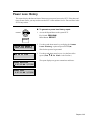
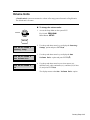
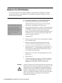
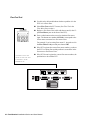
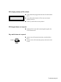
1
Draft Sentinel Installation/Service
and User Manual
September 1999
BERG COMPANY, LLC
FCC Information:
This device complies with Part 15 of FCC rules. Operation is subject to the following two conditions:
(1) This device may not cause harmful interference and, (2) this device must accept any interference
received including interference that may cause undesired operation.
Note: The user is cautioned that any changes or modifications not expressly approved by the party
responsible for FCC compliance could void the user’s authority to operate the equipment.
Copyright © 1998, 1999 by Berg Company. All rights reserved.
No part of this publication may be reproduced, transmitted, transcribed, stored in a retrieval system, or
translated into any language in any form by any means without the written permission of Berg
Company, Madison, Wisconsin.
Trademarks
Draft Sentinel is a registered trademark of Berg Company, a Wisconsin Limited Liability Company.
Other brand and product names may be trademarks or registered trademarks of their respective
companies.
Berg Part Number: 8002955
Printed in U.S.A.
Disclaimer of Limited One Year Warranty
Warranties and
Berg Company, LLC (BERG) warrants that all
Liabilities its Control Systems (SYSTEMS) will remain free from defects in materials
and workmanship for a period of one (1) year from the date of original
installation. BERG’S obligation under this Warranty shall be limited to the
repair or replacement (at BERG’S option) of the SYSTEM or its defective
part(s) during the warranty period. This Warranty is not assignable and is for
the benefit of the original end-user purchaser only. BERG neither assumes nor
authorizes anyone to assume on its behalf any obligations not covered by the
Warranty.
THIS WARRANTY IS EXCLUSIVE AND IS IN LIEU OF ALL OTHER
WARRANTIES, ORAL OR WRITTEN, EXPRESS OR IMPLIED, INCLUDING THE WARRANTIES OF MERCHANTABILITY AND FITNESS FOR
ANY PARTICULAR PURPOSE.
CONDITION AND EXCLUSIONS
No defect (failure) caused by misuse, abuse, improper installation, lack of
normal care or maintenance, accident or Act of God is covered by the
foregoing Warranty. Said Warranty is limited to repair or replacement (at
BERG’S option) only and does not include any labor or transportation charges
or compliance with any Federal, State or local laws, codes or regulation.
Notice of any claimed breach of said Warranty must be promptly given to the
authorized dealer from whom the System was purchased or leased. Upon
request, all Systems or parts which are claimed to be defective must be made
available for inspection by and/or return to (at BERG’S option) such authorized dealer and/or BERG. No repair or replacement under said warranty will
extend the original warranty period.
LIMITATION OF LIABILITY
IN NO EVENT SHALL BERG BE LIABLE UNDER ANY TORT, CONTRACT OR OTHER LEGAL THEORY FOR ANY LOSS, COST, EXPENSE
OR INCIDENTAL OR CONSEQUENTIAL DAMAGES OF ANY KIND IN
CONNECTION WITH THE DESIGN, SALE, USE, REPAIR AND/OR
REPLACEMENT OF ANY SYSTEM OR PART THEREOF, EXCEPT AS
SPECIFICALLY NOTED ABOVE.
BERG COMPANY
Disclaimer of Other Warranties and Liabilities
While all reasonable care has been taken in preparation of this product, it is
provided “as is,” without warranty as to performance or fitness except as
expressly stated above. The entire risk as to the quality of output developed
with this product is assumed by the user.
Berg Company does not warrant that the software or system will meet any
particular requirements of the user, other than as expressly stated above, and
specifically denies any liability for incidental or consequential damages
resulting from the use of this software or system.
Berg Company also specifically denies all liability for any technical or
editorial omissions in its product documentation, and for any incidental or
consequential damages resulting from the furnishing, performance or use of its
documentation.
Contents
Safety
General Safety Precautions ........................................................................... iv
Safety Terms and Symbols ............................................................................. v
Getting Started
1-1
Draft Sentinel System Components ............................................................. 1-2
Installation Game Plan and Checklist ..........................................................1-3
Gather Customer Setup Information ............................................................1-4
Tools and Materials Required ......................................................................1-6
ECU Menus ..................................................................................................1-7
Hardware Installation
2-1
Install the ECU .............................................................................................2-2
Insert Flow Meters in Beverage Lines .........................................................2-4
Install Flow Meter J-Box ...............................................................................2-6
Wire Flow Meter Cables to Flow Meter J-Boxes .......................................... 2-8
Wire Flow Meter J-Box Cable to the ECU ................................................. 2-10
Flow Test.................................................................................................... 2-12
Set Time and Date .................................................................................... 2-13
Connect the ECU to a Computer .............................................................. 2-14
Beverage Manager Software
3-1
Install the Software ......................................................................................3-2
Communication Settings .............................................................................. 3-4
Price and Volume Units ................................................................................ 3-5
Select an ECU Type ..................................................................................... 3-6
Transfer Data between the ECU and the Computer ....................................3-7
Flow Meter Setup .........................................................................................3-8
Print Setup Data ........................................................................................ 3-10
Calibrate Flow Meters ............................................................................... 3-12
Generate Reports ..................................................................................... 3-14
Detailed Z Report ...................................................................................... 3-16
Detailed X Report ...................................................................................... 3-18
Power Loss Report .................................................................................... 3-20
Prices and Portions Report ....................................................................... 3-22
Variance Report ........................................................................................ 3-24
Export ........................................................................................................ 3-26
Perform a Loopback Test........................................................................... 3-27
Perform a Communication Test ................................................................. 3-28
ii Draft Sentinel Installation/Service and User Manual
Flow Meter Setup
4-1
Set Up Brands .............................................................................................. 4-2
Calibrate Flow Meters .................................................................................. 4-3
Reports
5-1
Z Report .......................................................................................................5-2
X Report .......................................................................................................5-4
Power Loss History ......................................................................................5-5
Country Setup
6-1
Country Setup Default Values ...................................................................... 6-2
Volume Units ................................................................................................6-3
Set Date Format ...........................................................................................6-4
Set Time Format ...........................................................................................6-5
Maintenance
7-1
Replace the ECU PROM Chip .....................................................................7-2
Replace the ECU Battery .............................................................................7-4
Clean the ECU .............................................................................................7-6
Draft Sentinel
Specifications
8-1
Troubleshooting
9-1
Index
Contents iii
General Safety Precautions
Review the following precautions to avoid injury and to prevent damage to the product.
Precautions
n To reduce the risk of electric shock, use only in a dry indoor
location.
n To prevent the risk of electric shock connect the unit to a
properly grounded power source using an IEC approved 3pronged power cord. After installation of this equipment,
access to the power cord and the mains power source
receptacle must not be blocked or restricted.
n To avoid damage to the unit, be sure that the alternating
current (AC) power supply in your area is appropriate for
this equipment. Power requirements are detailed in the Draft
Sentinel Specifications section of this manual.
n For technical information about this product contact your
local Berg dealer or call the Berg Company at (608) 2214281 between the hours of 8:00 A.M. and 4:30 P.M. C.S.T.
iv Draft Sentinel Installation/Service and User Manual
Safety Terms and Symbols
Review the following terms and symbols to avoid injury and to prevent damage to the product.
Terms in This Manual
These terms may appear in this manual:
Warning. Warning statements identify conditions or practices
that could result in injury or loss of life.
Caution. Caution statements identify conditions or practices that
could result in damage to this product or other property.
Terms on the Product
These terms may appear on the product:
Caution indicates a hazard to property including this product.
Symbols on the Product
The following symbols may appear on the product:
Attention. Consult accompanying documents.
Contents v
SECTION
1
Getting Started
The general guidelines provided in this section can help you take the necessary
steps to make each Draft Sentinel installation run as smoothly as possible.
Draft Sentinel System Components ................................................ 1-2
Installation Game Plan and Checklist .............................................. 1-3
Gather Customer Setup Information ............................................... 1-4
Draft Sentinel Worksheet ................................................................. 1-5
Tools and Materials Required.......................................................... 1-6
ECU Menus ..................................................................................... 1-7
Draft Sentinel System Components
The Draft Sentinel dispensing system is designed to monitor up to 24 flow meters installed in the
beverage lines of any bulk liquid (draft beer, wine, juice, soda). A Draft Sentinel system is
composed of the following components.
ECU
(Electronic Control Unit)
A compact, lightweight console with a backlit LCD readout and
keypad that contains the “brains” of the system. One ECU can
control 24 flow meters. The ECU records the volume measured
by the flow meters and displays the totals in system reports.
Security is maintained at the ECU through a key switch. The
ECU may be connected to a computer with the use of Beverage
Manager software.
Flow meter J-Box
A junction box that can connect up to eight flow meters to the
ECU through one cable. Using junction boxes saves installation
time and reduces the number of cables required. Each ECU can
be connected to 3 flow meter J-boxes.
Flow meter
Beverage Manager
Software
The flow meter is installed in the beverage line to monitor the
volume of drinks poured. It operates with a turbine magnet with
pulses based on volume. The ECU reads the flow meter to record
the total volume dispensed through the line. The flow meter is
usually installed in a section of the line inside the cooler.
Provides convenient, protected access to setup and report data.
Allows printing of system reports.
BERG
1-2 Draft Sentinel Installation/Service and User Manual
Installation Game Plan and Checklist
Berg offers the following checklist to expedite your installation of a Draft Sentinel system. To help
you locate information quickly, related tasks are grouped throughout the manual.
Getting Started q 1.
Section 1
Gather customer setup information and make preliminary
ordering plans.
q 2. Submit order to Berg, assemble required tools and materials
and set installation date.
q 3. Perform any pre-installation setup of the Draft Sentinel
ECU.
Hardware Installation q 4.
Section 2
q 5.
Install the ECU.
Install flow meters.
q 6. Install and connect flow meter junction boxes.
q 7. Test each flow meter connection using Flow Test.
q 8. Set the ECU’s time and date
q 9. Connect the ECU to a computer (if using software).
Beverage Manager Software q 10. Install the software.
Section 3
(if using software) q 11. Enter flow meter setup information.
q 12. Calibrate flow meters.
Flow Meter Setup q (9). Enter brand names for each flow meter.
Section 4
(if not using software) q (10).Calibrate flow meters.
Country Setup q
Section 6
(if necessary)
Change default country setup values.
Getting Started 1-3
Gather Customer Setup Information
Sketch out a rough map of the proposed system’s layout and size to clarify with the customer.
Mounting Surfaces
Cable and Tubing Paths
Determine the suitability of all equipment mounting surfaces.
Check for available space, proximity to bartender and protection
from moisture. Modify surfaces as necessary.
Determine the lengths and paths of cable and tubing. All cables
must be a safe distance (12 in) from any high-current devices
(transformers and dishwashers), any heat sources (water pipes,
light bulbs) and any sharp objects. Note any impediment to cable
and tubing paths and either relocate the impediment or modify the
path.
Draft Sentinel ECUs
Order one ECU for every 24 flow meters. The ECU must be
located within 500 ft (152.4 m) of any flow meters and within 5
1/2 ft (1.7 m) of a reliable AC outlet. The operating temperature
range for the ECU is from 5° C to 40° C (41° F to 104° F).
Power Supply
If your AC power source is not 110-120VAC, 60 Hz, obtain one
power supply per ECU. See the Draft Sentinel Specifications
section for the specific requirements of the power supply.
Flow Meters
Order one flow meter for every beverage line. The flow meters
must be located within 500 ft (152.4 m) of the ECU.
Flow Meter J-Boxes
Order one flow meter J-box for every 8 flow meters. If the flow
meters are installed in beverage lines inside a cooler, the flow
meter J-box is usually mounted on a wall inside the cooler.
Computer (optional)
If the system includes Beverage Manager software, plan the
connection route between the ECU and the computer.
Draft Sentinel
Worksheet
Make a copy of the Draft Sentinel Worksheet. Record the brand
names for each line in the system. You don’t need to match a flow
meter number to each brand at this point. If you’ll be using
Beverage Manager software you can also record a price per unit
for each brand. The price per unit is used to determine the retail
value of the volume poured on detailed X and Z reports. You’ll
fill in the flow meter number, calibration amount poured and final
meter count when you finish the system installation.
1-4 Draft Sentinel Installation/Service and User Manual
Draft Sentinel Worksheet
FM
Brand Name
Price/Unit
Cal amount
poured
Meter
Count
Getting Started 1-5
Tools and Materials Required
Berg offers the following list to help in your preparation for a Draft Sentinel installation.
Tools Required
þ
þ
þ
þ
þ
þ
þ
þ
þ
þ
þ
þ
þ
þ
þ
Small slotted screwdriver
Large pair of pliers
Small Phillips (#2 pt.) screwdriver
Small needlenosed pliers
Utility knife
Fish tape
Diagonal cutters
Thermometer
Small jeweler’s screwdriver
Tubing cutter
Tubing clamps
Beer nut wrench
Wire stripper for 22 and 24 AWG wire
Measuring cup
Jacket for working in cooler
You may also need saws, drills, holesaws, and possibly other
power tools. To be safe, you may want to bring all the tools you
have.
Materials Required
þ Various flow meter fittings
þ Tie-straps
þ Cable hold-downs
It’s best to have extra of these items—enough to cover a worst
case scenario.
Berg offers a Beer Toolkit that includes a spanner wrench,
thermometer, jeweler’s screwdriver, tubing cutter, tubing clamps,
flow meter fittings, tees for air tubing and splices for air tubing.
Equipment Preparation
Make sure the Draft Sentinel equipment arrives at your shop a
few days before you plan to install the system. Open the boxes
and check to see you have everything you need. Also, verify
nothing was damaged during shipping.
1-6 Draft Sentinel Installation/Service and User Manual
ECU Menus
The LCD display on the ECU functions like a narrow window, highlighting your current position
in a menu. You use the up and down arrows and the enter key to control your movement through
the menus and to select your options.
Key Switch
Turn the key to PROGRAM to use the ECU menus.
PROGRAM
OPERATE
Menu Buttons
Select a menu using either the Setup or Report button.
SETUP
Reading the Display
Use ↑↓ and ENTER ↵
Flow Meter Setup
ECU Menus
REPORT
The display window on the ECU shows two lines of text at a
time. The first line is normally a prompt asking you to take some
action. For instance, Use ↑↓ and ENTER ↵ means use the up
and down arrow keys to change your position in the menu and
ENTER to select an option. The left and right arrows are used to
move the cursor through the characters of an entry field.
Setup Menu
Exit This Menu
Flow Meter Setup
Exit This Menu
Flow Test
Setup Brand 1
Setup Brand 2
s
s
s
Setup Brand 24
Set Time and Date
Country Setup
Exit This Menu
Set Volume Unit
Set Date Format
Set Time Format
Report Menu
Exit This Menu
Z Report
X Report
Power Loss History
Getting Started 1-7
SECTION
2
Hardware Installation
Refer to this section for help with the following tasks:
Install the ECU ................................................................................ 2-2
Insert Flow Meters in Beverage Lines ............................................. 2-4
Install Flow Meter J-Box ................................................................. 2-6
Wire Flow Meter Cables to Flow Meter J-Boxes ............................ 2-8
Wire Flow Meter J-Box Cable to the ECU .................................... 2-10
Flow Test ....................................................................................... 2-12
Set Time and Date ......................................................................... 2-13
Connect the ECU to a Computer ................................................... 2-14
Install the ECU
Locate the Draft Sentinel ECU in a location where moisture, unwanted access and heavy falling
objects will not be a problem.
n To install the ECU:
1. Choose a secure, dry location for the ECU.
The ECU must be located within 500 ft (152.4 m) of any
flow meters and within 5 1/2 ft (1.7 m) of a reliable AC
outlet. The operating temperature range for the ECU is from
5° C to 40° C (41° F to 104° F).
2. Set the ECU on a shelf or table or attach it to a wall.
To attach it to a wall, remove the 4 screws that hold the cover
to the base and pull the stick-on feet off the base to reveal 4
mounting holes.
3. Plug the cable end of the power supply into the PWR port on
the front of the ECU. (For power supply specifications, see
the Draft Sentinel Specifications section.)
4. Plug the power supply into the AC outlet only when you've
finished any wiring tasks, including wiring flow meter Jboxes.
2-2 Draft Sentinel Installation/Service and User Manual
Machine screws
Power supply
plug-in
Optional RJ-11
connection to
computer
15-pin port for
flow meters 17-24
15-pin port for
flow meters 1-8
15-pin port for
flow meters 9-16
Draft Sentinel ECU
Hardware Installation 2-3
Insert Flow Meters in Beverage Lines
If you need to install specific flow meter numbers in specific beverage lines, number the cable ends
of each flow meter to keep track of them. Alternatively, simply install any flow meter in any
beverage line and then determine which flow meter goes with each brand at the ECU.
n To insert flow meters:
1. Make sure any spouts are closed and the door to the beverage
cooler is closed.
If you leave the cooler door open, the temperature of the
beverage will rise which causes excess foaming and makes
calibration difficult.
2. Turn off pressure to the beverage line.
3. Determine where to insert the flow meter in the line. Plan
enough length in the line to secure the flow meter to the wall
or other surface.
4. Cut the beverage line.
5. Install the flow meter into the beverage line. First slide
clamps around each end of the cut line, then insert the flow
meter and tighten the clamps. Make sure the flow meter is
installed with the “flow” arrow pointing toward the end of the
tube that goes to the spouts.
The flow meter is originally
calibrated in a vertical position,
so this is the preferred position
for mounting.
6. Mount the flow meter to the cooler wall (or other place) with
#6 wood or sheet metal screws.
You can mount the flow meter vertically on the wall or
horizontally on a shelf. Do not mount the flow meter at a
diagonal or any other angle. If you mount it horizontally, be
sure the bracket is on the bottom or top of the flow meter and
not the side.
2-4 Draft Sentinel Installation/Service and User Manual
Flow meter
Beverage line from
storage container
Beverage line to
point of dispense
Mounting bracket
3 conductor cable to
flow meter J-box
Vertically mounted
flow meter
Horizontally mounted
flow meter
Hardware Installation 2-5
Install Flow Meter J-Box
The flow meter J-box must be connected to the ECU with 10 conductor cable. If you are dealing
with a draft system and beverage cooler operations, you may want to consult with the beverage
distributor as you plan cabling routes through the walls of the cooler. Remember to keep the cooler
door closed.
n To install a flow meter J-box:
1. Run 10 conductor cable from the ECU to the flow meter Jbox. Avoid heat sources, light sources, moisture, chemicals,
appliances and sharp objects.
2. Carefully cut a small hole in the caulk or putty between the
beverage lines and the wall of the cooler for inserting the 10
conductor cable. Repeat this step for the outside wall, or
outside of the cooler. (We do not recommend drilling new
holes in the cooler for running cables because you run the risk
of breaking a coolant line.)
3. Fish the cable through the walls of the cooler, making sure
you have enough cable at the flow meter J-box and at the
ECU.
4. Seal the cables at the walls of the cooler with silicone sealant.
5. Remove the cover and mount the flow meter J-box using the
four screws provided (or by some other means) making sure
you miss any coolant lines if you drill.
6. Carefully strip approximately 3 in (7.6 cm) of outer
insulation from the 10 conductor cable going to the flow
meter J-box.
7. Carefully strip approximately 3/16 in (.5 cm) of insulation
from each individual wire in the 10 conductor cable.
8. Remove the black cover from the single cable port on the
outside of the flow meter J-box. Insert the 10 conductor cable
through the port making sure the cable’s outer insulation is in
the connector. Tighten the connector.
9. Connect the individual wires of the 10 conductor cable to the
10 conductor terminal block inside the flow meter J-box.
Loosen the terminal screws and match each color wire to its
appropriate slot. Tighten the terminal screws.
10. Replace the cover on the flow meter J-box.
2-6 Draft Sentinel Installation/Service and User Manual
10 conductor cable from flow
meter J-box to 10 conductor
flow meter pigtail on ECU
Cable port
10 conductor terminal
block
Mounting screws to attach
flow meter J-box to cooler
wall
Hardware Installation 2-7
Wire Flow Meter Cables to Flow Meter J-Boxes
Typically, the flow meter J-box is mounted on a wall above the vertically mounted flow meters.
Avoid moisture and unwanted access. Remember if you're working in a cooler to keep the door
closed the entire time you're working inside so the temperature of the beverage won't rise.
n To wire flow meter cables to flow meter J-boxes:
1. Run the cables from the flow meter to the planned location of
the flow meter J-box.
2. Remove the cover of the flow meter J-box by removing the
four screws.
3. Carefully strip approximately 1.5 in (3.8 cm) of outer
insulation from the end of the flow meter cables.
4. Carefully strip approximately 3/16 in (.5 cm) of insulation
from the three individual wires in the flow meter cables.
5. Remove the black covers from the cable ports on the outside
of the flow meter J-box. Insert the cable from flow meter 1
into the port that is closest to the terminal block labeled FM
1. Make sure that the cable’s outer insulation is in the
connector. Tighten the connector with a 3/4 in wrench until
the cable is secure.
6. Loosen the terminal screws in the block labeled FM 1. Insert
the red, black and white wires from the flow meter cable into
the appropriate spaces on the terminal block. Tighten the
terminal screws.
Repeat steps 5 and 6 for each flow meter installed, making
sure flow meter 2 connects to the terminal block labeled FM
2, flow meter 3 connects to FM 3, and so on.
2-8 Draft Sentinel Installation/Service and User Manual
Connect the red wire to
RED, black to BLK, and
white to WHT.
Cable ports
3 conductor cable from flow
meter 1. (Feed this cable
through the port closest to
the FM 1 terminal block.)
Hardware Installation 2-9
Wire Flow Meter J-Box Cable to the ECU
You should already have a length of 10 conductor cable running from the flow meter J-box to the
ECU.
n To wire flow meter J-box cables to the ECU:
1. Disconnect power from the ECU.
2. Splice the 10 conductor pigtail on the back of the ECU to the
10 conductor flow meter J-box cable using the Scotchlok
connectors provided. This is a direct color-to-color splice.
Connect white to white, green to green, orange to orange, etc.
until all ten conductors are spliced.
Red
Black
White
Green
Orange
Blue
Brown
Yellow
Violet
Gray
It's very important to use Flow
Test at this point to verify you
have a flow meter correctly wired
and installed in each beverage
line and that you know which
flow meter number goes with
each brand. If you omit this test,
any errors in installation will
only cause trouble later on.
Power
Ground
Flow Meter 1
Flow Meter 2
Flow Meter 3
Flow Meter 4
Flow Meter 5
Flow Meter 6
Flow Meter 7
Flow Meter 8
3. Restore power to the ECU and verify your connections using
Flow Test in the Setup menu. See Flow Test in this section.
2-10 Draft Sentinel Installation/Service and User Manual
15-pin port for
flow meters 1-8
15-pin port for
flow meters 9-16
15-pin port for
flow meters 1724
Hardware Installation 2-11
Flow Test
This test shows you which flow meter number registers the pour of a specific brand. Use it to
verify the correct installation of flow meters and to determine which flow meter number
corresponds to each brand. (Unless you need a specific flow meter number assigned to a specific
brand, you can just install all the flow meters and then use Flow Test to determine which brand is
brand 1, brand 2 and so on.)
n To use flow test:
1. Access the Setup Menu on the system ECU.
PROGRAM
Key Switch: PROGRAM
Menu Button: SETUP
OPERATE
SETUP
Use ↑↓ and ENTER ↵
Flow Meter Setup
2. Use the up and down arrow keys to display the Flow
Meter Setup option and press ENTER(↵).
Use ↑↓ and ENTER
Flow Test
3. Use the up and down arrow keys to display the Flow
Test option and press ENTER(↵).
↵
4. Pour a drink of the brand you want to test. During the pour,
the ECU window displays the flow meter number that
registers the pour.
PRESS ↵ To EXIT
Flow On: 1
PRESS ↵ To EXIT
Flow On: None
Write down the correct flow meter number for each brand on
the Draft Sentinel Worksheet. (If the flow meter number is
different than what you expected, you probably switched the
wiring on a couple of flow meters.)
If the ECU window displays None during a pour, verify that
a flow meter is installed in the line and that all wiring
connections are correct.
5. Press ENTER(↵) to exit the test. The display returns to the
Flow Test option.
Note
q You can now use the Draft Sentinel Worksheet to enter flow
meter and brand setup information using Beverage Manager
software or the ECU setup menu. See the Beverage Manager
Software section or the Flow Meter Setup section.
2-12 Draft Sentinel Installation/Service and User Manual
Set Time and Date
Once you've made all your connections and plugged in the ECU, use this menu item to establish the
correct time and date for your system. The ECU keeps track of power losses using the time and
date you set.
n To set the ECU time and date:
1. Access the Setup Menu on the system ECU.
PROGRAM
Key Switch: PROGRAM
Menu Button: SETUP
OPERATE
SETUP
2. Use the up and down arrow keys to display the Set Time
and Date option and press ENTER(↵).
Use ↑↓ and ENTER ↵
Set Time and Date
↑↓
↑↓g and ENTER
Use f↑↓
10:56:12 AM
↵
3. Use the up and down arrow keys to select the numbers of the
correct time and press ENTER(↵).
The left and right arrow keys move the cursor through the
time and date fields. To change AM to PM, cycle through the
hour field.
↑↓
Use f↑↓
↑↓g and ENTER
1/14/99
↵
4. Use the up and down arrow keys to select the numbers of the
correct date and press ENTER(↵).
The display returns to the Set Time and Date
option.
Notes
q To change the time format from 12 hour to 24 hour notation
see Set Time Format in the Country Setup section.
q To change the date format from MM/DD/YY to
DD.MM.YY, see Set Date Format in the Country Setup
section.
Hardware Installation 2-13
Connect the ECU to a Computer
If you are installing Beverage Manager software to use with your Draft Sentinel, you need to
provide a connection between a computer and the ECU. Connecting to a computer requires the RS232 / RS-485 converter (Berg PN 8009344-North America or PN 8009345-International).
n To connect the ECU to a computer:
1. Plug the connector from the power transformer into the side
of the RS-232 / RS-485 converter.
2. Plug the power transformer into the same buffered power
strip used by the computer.
3. Insert the RS-232 / RS-485 converter into a serial port of the
computer and secure it with the captive screws in the
connector flanges.
If the converter does not fit in the serial port, insert a 9-to-25
pin adapter cable.
4. Insert the communication cable plug into the RJ-12 socket on
the converter.
5. Insert the other end of the communication cable into the
COMM port on the back of the ECU.
Note
q See the Beverage Manager Software section for help with
installing the software and using it to communicate with the
ECU.
2-14 Draft Sentinel Installation/Service and User Manual
Power
transformer
Insert in computer
serial port
Communication cable
plug from ECU
RS-232 / RS-485
converter
RS-232 / RS-485
converter
Computer
COMM port
Hardware Installation 2-15
SECTION
3
Beverage Manager
Software
Beverage Manager software provides a convenient alternative to data entry at the
ECU. To use the software, be sure you've installed a connection from the ECU to
your computer. See Connect the ECU to a Computer in the Hardware
Installation section. See the online help accompanying the software or use this
section for help with the following tasks:
Install the Software .......................................................................... 3-2
Communication Settings .................................................................. 3-4
Price and Volume Units ................................................................... 3-5
Select an ECU Type ........................................................................ 3-6
Transfer Data between the ECU and the Computer ........................ 3-7
Flow Meter Setup ............................................................................ 3-8
Print Setup Data ............................................................................ 3-10
Calibrate Flow Meters ................................................................... 3-12
Generate Reports ........................................................................... 3-14
Detailed Z Report .......................................................................... 3-16
Detailed X Report .......................................................................... 3-18
Power Loss Report ........................................................................ 3-20
Prices and Portions Report ............................................................ 3-22
Generate a Variance Report ........................................................... 3-24
Export ............................................................................................ 3-26
Perform a Loopback Test .............................................................. 3-27
Perform a Communication Test ..................................................... 3-28
Install the Software
Beverage Manager software comes with its own install program. Simply respond to its prompts
for an easy software installation. To communicate with the Draft Sentinel ECU, your computer
must be linked to the ECU using the converter assembly that comes with the software. See Connect
the ECU to a Computer in the Hardware Installation section.
n To install Beverage Manager software:
1. Close all other programs running under Windows.
2. Insert the Beverage Manager disk in a floppy disk drive.
3. Click File in Program Manager (Windows 3.1), or click Start
(Windows 95, NT).
Click Run.
4. Type a:\setup (where a
is the floppy disk drive
letter) and click OK.
5. Follow the instructions
on your screen. Click
Next to continue through the setup process or Back to return
to a previous screen Click Cancel to stop the setup process.
6. Enter the dealer's name and phone number for technical
support and click Next. (The Berg Company name and phone
number are used if you don't enter a dealer name.)
3-2 Draft Sentinel Installation/Service and User Manual
7. Click Next to accept the default destination directory
(C:\BERGAB) for the software. If you prefer a different
destination, enter a new directory.
8. Click Next to accept the program group or folder for the
placement of Beverage Manager program icons. Or, if you
prefer, enter a different group or folder.
9. Click Finish to complete the software installation.
When setup is complete,
double-click on the
Beverage Manager
icon in the Berg
Beverage Manager
folder to use the software.
You may be prompted to re-start your computer before you
can run Beverage Manager. You can let the install program
re-start your computer or do it yourself at a later time.
Beverage Manager Software 3-3
Communication Settings
The number of the computer COM port that connects the ECU to the computer must be correctly
entered in the software or communication can't take place.
n To change communication settings:
1. Click Setup on the Beverage Manager menu bar.
2. Click Communication Settings....
3. Click the COM port your computer uses to communicate with
the ECU.
4. Click OK to save your selections.
The software stores your selections, so you don't have to reset
them each time you start the program.
Notes
q The only baud rate for communicating with a Draft Sentinel
ECU is 9600.
q You can test ECU/computer communication with the Identify
button on the Select ECU Type screen. See Select an ECU
Type in this section.
Click OK to save
your choice and
return to the
main menu.
Click Cancel to return
to the main menu
without saving any
changes.
3-4 Draft Sentinel Installation/Service and User Manual
Click Help if
you have
questions.
Price and Volume Units
The volume unit at the computer must match the volume unit entered at the ECU. You can also
enter a price format (used when you enter a price per unit for your brands).
n To change price and volume unit settings:
1. Click Setup on the Beverage Manager menu bar.
2. Click Price & Volume Units....
3. Click a price format (not necessary if you're not entering a
price per unit for your brands).
4. Click the volume units used at the ECU.
5. Click OK to save your selections.
The software stores your selections, so you don't have to reset
them each time you start the program.
Click OK to save
your choice and
return to the
main menu.
Click Cancel to return
to the main menu
without saving any
changes.
Click Help if
you have
questions.
Beverage Manager Software 3-5
Select an ECU Type
You must specify your ECU type for the software to correctly access and transfer data to the ECU.
n To select an ECU type:
1. Click Setup on the Beverage Manager menu bar.
2. Click Select ECU type....
Identify
3. Click Draft Sentinel.
If you have multiple types of
ECUs in your system, click
Identify to determine which type
of ECU is connected to the
COM port you've specified.
4. Click OK to save your selection.
The software stores your selection, so you don't have to reset
it each time you start the program.
Note
q You can use the Identify button to verify communication
between the computer and ECU. Intentionally select a wrong
ECU type and click Identify. If communication occurs, the
correct ECU type will be selected. If no communication
occurs, you'll see an error message.
3-6 Draft Sentinel Installation/Service and User Manual
Transfer Data between the ECU and the Computer
An important part of entering data with Beverage Manager is getting data from the computer to
the ECU and back again. Transferring data is easy, but it's important to understand which data
you're working with at all times.
n To transfer data from the ECU to the computer:
1. Click Setup on the Beverage Manager menu bar.
2. Click Prices/Portions/PLUs....
3. Click Read ECU.
Wait while the data is transferred from the ECU to the
computer.
4. Enter or edit the correct data. See Flow Meter Setup in this
section.
n To transfer data from the computer to the ECU:
1. Click Setup on the Beverage Manager menu bar.
2. Click Prices/Portions/PLUs....
3. Enter or edit the correct data. See Flow Meter Setup in this
section.
4. Click Load ECU.
Wait while the data is transferred from the computer to the
ECU. The new data overwrites any data previously entered at
the ECU or previously sent to the ECU from the computer.
Notes
q Communication settings, price format and volume units at the
ECU and computer must match. See Communication Settings
and Price and Volume Units in this section.
q You can't perform other operations in Beverage Manager
while the data is being transferred.
q If you encounter difficulty communicating with the ECU, see
the Troubleshooting section.
Beverage Manager Software 3-7
Flow Meter Setup
Beverage Manager software provides one convenient table for entering all flow meter and brand
data.
n To enter flow meter and brand data:
1. Click Setup on the Beverage Manager menu bar.
2. Click Prices/Portions/PLUs....
3. To enter data for the first time proceed with step 4.
To edit existing flow meter data in the ECU click Read ECU.
To edit a file you've previously saved at the computer click
Open and enter the name of the file you want to edit.
4. Select the correct row and column in the table using arrow
keys, the Tab key, the Enter key or a mouse.
5. Type the brand name that corresponds to each flow meter.
The ECU only stores the first 10 characters of the brand
name you enter.
6. Type the retail price per volume unit for each brand
(optional). This price is used on sales reports to calculate the
approximate retail value of the volume poured. (For example,
if you usually charge $1.20 for a 12 oz beer, enter .10 as the
price per unit.)
7. Type the flow meter count for each flow meter. (This number
is on the label of the flow meter.)
8. Click Save to save the flow meter data in a computer file.
Enter the name you want to give the file and click OK.
9. Click Load ECU to download flow meter data to the ECU
(see Transfer Data between the ECU and the Computer in
this section).
10. Click Print Prices and Portions to print the flow meter
entries you've made (see Print Setup Data in this section).
3-8 Draft Sentinel Installation/Service and User Manual
Click Close
to return to
the main
menu.
Use the arrow keys, the Tab
key, the Enter key or a
mouse to move between rows
and columns. If you make a
mistake, use the Delete key
to erase any amount
currently highlighted.
Click Open to view a
previously saved file.
Click Save to replace
previous data in the
file with the new data.
Click Save As... to
save the file under
a new name.
Click Print Prices &
Portions for a
report listing flow
meter setup data.
Click Help if
you have
questions.
Click Read or Load the ECU
to transfer data. Price format and
volume units at the ECU and
computer must match. You cannot
perform other operations while the
data is being transferred.
Beverage Manager Software 3-9
Print Setup Data
You can print a copy of brand and flow meter data entered at the computer.
n To print setup data:
1. Click Setup on the Beverage Manager menu bar.
2. Click Prices/Portions/PLUs....
3. Perform the necessary steps to enter or edit the correct data.
See Flow Meter Setup in this section.
4. To brand and flow meter data: Click Print Prices &
Portions.
The flow meter data appears in a Notepad window. You can
now treat the data as you would any other computer file
(save, print, delete, etc.).
5. Click File on the menu bar.
6. Click Print to print the data.
7. Click Save As..., enter the name of the file and click OK to
save the data.
8. To exit the Notepad window and return to the Price/Portion/
PLU Setup screen, click Exit from the File menu.
Notes
q The setup data printed from the Notepad window shows the
current entries in the Price/Portion/PLU Setup screen. It
does not reflect the current entries in the ECU unless you just
performed a Read ECU or Load ECU and made no further
changes to the Setup screen.
q The setup data reports are distinguished from other sales or
ECU reports by the words "Current Settings" at the top of the
report.
3-10 Draft Sentinel Installation/Service and User Manual
The Notepad
window
Select Save
As... to save
the report to
a new file.
Select Print
to send the
report to a
printer.
Select Exit to
return to the
Setup screen.
Beverage Manager Software 3-11
Calibrate Flow Meters
Beverage Manager software performs the calibration equations for you when you enter the amount
of your calibration pours.
n To calibrate flow meters:
1. Click Setup on the Beverage Manager menu bar.
2. Click Calibration....
3. Select a flow meter number (1-24) to calibrate or select All.
4. Click Continue....
5. Click OK after reading the message about entering
calibration mode.
6. Go to the appropriate spout and pour a large portion (Berg
recommends at least 12 oz) into a measuring cup or
graduated cylinder. Write down the exact amount poured. If
you selected All flow meters, pour and record the amount
poured for each brand.
Draft Sentinel Worksheet
Use the worksheet from the
Getting Started section to
record the amount poured and
also the final meter count for
each brand. Save the worksheet
for future reference.
7. At the computer type the volume units you measured for the
appropriate flow meter and click OK (or Continue... if you
selected all flow meters).
3-12 Draft Sentinel Installation/Service and User Manual
The volume units measured by the flow meter are displayed
along with the new flow meter count automatically entered by
the software.
8. Click OK after reading the new count.
9. If you selected All flow meters, repeat steps 7 and 8 for each
flow meter.
10. If you selected a single flow meter number, repeat steps 3-8
for any other flow meter that needs to be calibrated.
11. Click Cancel to exit the calibration process.
Note
q If you're not satisfied with the level of accuracy obtained by
the calibration process, perform the procedure again. The
software calculates a new flow meter count each time you
perform the steps. Each new flow meter count should increase
the flow meter's level of accuracy.
Beverage Manager Software 3-13
Generate Reports
The reports that can be generated from your Draft Sentinel ECU can also be generated with
Beverage Manager. The software-generated X and Z reports provide the retail value of the
amount poured in addition to the number of volume units. For detailed information on each report
see Detailed Z Report, Detailed X Report, Power Loss Report, Price/Portion Report and
Generate a Variance Report in this section.
n To generate reports:
1. Click Reporting on the Beverage Manager menu bar.
2. Click Reports....
Prices and Portions
This report provides the same
information as the Print Prices
and Portions button on the
Price/Portion/PLU Setup screen.
It lists the current flow meter
and brand settings at the ECU.
3. Select the report and click OK (or double-click).
4. If prompted, click Yes to proceed with a Z report.
5. View the report in a Notepad window.
3-14 Draft Sentinel Installation/Service and User Manual
The Notepad
window
Click Save As... to
save the report
to a new file.
Click Print to
send the report
to a printer.
Click Exit to
return to the
Reports screen.
n To print the report:
1. Click File on the Notepad menu bar.
2. Click Print.
n To save the report in a new file:
1. Click File on the Notepad menu bar.
2. Click Save As....
3. Type the name to give your file.
4. Click OK.
Beverage Manager Software 3-15
Detailed Z Report
The Z report zeroes out all volume measurement and retail value totals at the ECU. Each Z report
is numbered for easy tracking. The report also informs you if any power has been lost to the ECU
since the last Z.
Time and Date
Z Number
Power Lost since last Z
Flow Meter
Brand Name
Volume Units Poured
Retail Value
The Time and Date on the report are the time and date the report
was run.
Z Number is the number of times a Z report has been run.
If there has been a power loss at the ECU since the last Z report,
you'll see this notification. If you want to see the exact date(s)
and time(s) of the power loss(es), run a Power Loss History
report.
The first column lists the flow meter numbers.
The second column lists the brand names that correspond to each
flow meter.
The third column shows the total volume units measured by the
flow meter for each brand since the last Z report.
The final column displays the retail value of the volume units
poured for each brand. This value is the price per unit you entered
for the brand multiplied by the total volume for the brand. To
change the price per unit, see Price and Volume Units in this
section.
3-16 Draft Sentinel Installation/Service and User Manual
Sample Detailed Z Report
Beverage Manager Software 3-17
Detailed X Report
The Detailed X report is identical to the Detailed Z report. However, the X report does not zero out
any volume or retail value totals.
Time and Date
Z Number
Power Lost since last Z
Flow Meter
Brand Name
Volume Units Poured
Retail Value
The Time and Date on the report are the time and date the report
was run.
Z Number is the number of the most recent Z report.
If there has been a power loss at the ECU since the last Z report,
you'll see this notification. If you want to see the exact date(s) and
time(s) of the power loss(es), run a Power Loss History report.
The first column lists the flow meter numbers.
The second column lists the brand names that correspond to each
flow meter.
The third column shows the total volume units measured by the
flow meter for each brand since the last Z report.
The final column displays the retail value of the volume units
poured for each brand. This value is the price per unit you
entered for the brand multiplied by the total volume for the
brand. To change the price per unit, see Price and Volume Units
in this section.
3-18 Draft Sentinel Installation/Service and User Manual
Sample Detailed X Report
Beverage Manager Software 3-19
Power Loss Report
This report details the exact date and time of the most recent power losses to the ECU.
Time and Date
The Time and Date on the report are the time and date the report
was run.
Power Restored
The date and time of each power restoration is listed starting with
the most recent occurrence.
Power Lost
The date and time of each power loss is listed starting with the
most recent occurrence.
3-20 Draft Sentinel Installation/Service and User Manual
Sample Power Loss Report
Beverage Manager Software 3-21
Prices and Portions Report
This report lists the current flow meter number, meter count and retail price per unit of each brand.
The report lists the values currently loaded at the ECU.
Time and Date
Flow Meter
The Time and Date on the report are the time and date the report
was run.
The first column lists the flow meter numbers.
Brand Name
The second column lists the brand names that correspond to each
flow meter.
Price per unit
If you've entered a retail price per unit for your brands, the prices
are listed. (This is an optional entry. The price per unit is used to
figure the retail value of the volume poured.)
Meter Count
The current meter count for each flow meter is listed. This
number determines the accuracy of the flow meter's calculation of
volume.
3-22 Draft Sentinel Installation/Service and User Manual
Sample Prices and Portions Report
Beverage Manager Software 3-23
Generate a Variance Report
To run this report you must enter the actual collected sales amount for each brand in the report.
The software then calculates the difference between the sales recorded at the ECU and the sales
recorded at the sales terminal. Any difference in the two amounts is shown and also figured as a
percentage.
n To generate a Variance report:
1. Be sure you've enabled the communication option at the ECU.
2. Select Reports... from the Beverage Manager menu bar.
3. Highlight Variance Report in the Reports list and click OK.
4. Type in the money collected at the sales terminal for the
brand specified and click OK.
5. Repeat step 4 for each brand as prompted. (Click Cancel to
exit the report at any time.)
6. View the report in a Notepad window.
3-24 Draft Sentinel Installation/Service and User Manual
Sample Variance Report
Reported Sales
Collected Sales
Variance
Pct. Collected
The total sales
recorded at the
ECU for each
brand.
The total sales
recorded at the
sales terminal for
the brand.
The discrepancy
between the
reported sales and
collected sales.
The percentage of
the sales amount
recorded at the ECU
that you actually
collected at the
sales terminal.
Beverage Manager Software 3-25
Export
You can export report data from a Draft Sentinel Detailed X report to other software applications.
To do this you tell the software where to save the report to a file. Check the documentation of your
other software applications for help with importing data.
n To export:
1. Click Reporting on the Beverage Manager menu bar.
2. Click Export....
3. Click Continue....
Export File Format
l
l
l
l
Data in the export file is
taken from current values at
the ECU.
The data on each line of the
export file is listed in the
following order: Flow meter
number, brand name, Z
number (of the most recently
run Z report), volume poured,
retail value.
The delimiting character is a
comma.
4. Select the folder where you want to save the export file.
5. Type a Filename for the export file. It will automatically be
given a .txt extension. Click Save.
Wait for the file to be saved.
Volume and retail values are
formatted with the correct
number of decimal places.
3-26 Draft Sentinel Installation/Service and User Manual
Perform a Loopback Test
Beverage Manager software provides diagnostic tests to verify communication between the ECU
and your computer. The loopback test verifies you have a working, accessible COM port on your
computer. You must have a loopback tester (Berg PN 8009196) to perform this test. The tester
comes with a cable and instructions.
n To perform a loopback test:
1. Click Diagnostics on the Beverage Manager menu bar.
2. Click Loopback Test....
3. Click Run to begin testing.
4. Unplug the RS-232/RS-485 converter from the COM port.
You should see failures. If you don't see errors BEFORE you
connect the loopback tester, the COM port is not available.
(Make sure you've specified the right COM port.)
5. Attach the loopback tester to the COM port.
If there are no errors, the COM port is OK. If there are
errors, either the COM port is incorrectly specified or the port
is defective.
6. You can continue testing by connecting the loopback tester at
various points in the connection (before or after the converter
or communication cable) to verify working equipment.
7. Click Stop to end the test.
8. Click Close to return to the main menu.
The number of tests run
should increase quickly.
You'll most likely see
100% failures or none
at all.
Click Run to begin
the test.
Click Stop to
stop the test.
Click Help if you
have questions.
Click Close to
return to the
main menu.
Beverage Manager Software 3-27
Perform a Communication Test
The communication test verifies the communication link between the ECU and your computer. It is
very useful when you're troubleshooting a communication problem.
n To perform a communication test:
1. Make sure the communication settings are correct at the ECU
and the computer.
2. Click Diagnostics on the Beverage Manager menu bar.
3. Click Communication Test....
4. Click Run to begin testing.
5. Click Stop to end the test.
6. Click Close to return to the main menu.
The number of tests run
should increase quickly.
You'll most likely see
100% failures or none
at all.
Click Run to begin
the test.
Click Stop to
stop the test.
3-28 Draft Sentinel Installation/Service and User Manual
Click Help if you
have questions.
Click Close to
return to the
main menu.
SECTION
4
Flow Meter Setup
If you're not using Beverage Manager software, once the flow meters are
installed you need to enter the correct brand name for each flow meter number at
the ECU. Calibrating the flow meters is an important step in the installation
process. You want the volume measured by the flow meters to correspond closely
to the actual volume poured.
Set Up Brands ................................................................................. 4-2
Calibrate Flow Meters ..................................................................... 4-3
Set Up Brands
You need to replace "brand 1", "brand 2", etc., with the names of the actual beverages used. Brand
1 corresponds to flow meter 1, brand 2 to flow meter 2, and so on.
n To set up brands:
PROGRAM
1. Access the Setup Menu on the system ECU.
OPERATE
Key Switch: PROGRAM
Menu Button: SETUP
SETUP
2. Use the up and down arrow keys to display the Flow
Meter Setup option and press ENTER(↵).
Use ↑↓ and ENTER ↵
Flow Meter Setup
Use ↑↓ and ENTER
Set Up Brand1
↵
3. Use the up and down arrow keys to display the Set Up
Brand(1-24) option and press ENTER(↵).
Use ↑↓ and ENTER
Name:BRAND01
↵
4. Press ENTER(↵) to move the cursor to the first character in
the brand name.
↑↓
Use f↑↓
↑↓g and ENTER
Name:BRAND01
↵
5. Key in the brand name (up to 10 characters) and press
ENTER(↵). The ECU saves the brand name and removes the
cursor.
Use the left and right arrow keys to move the cursor through
the brand name fields. Use the up and down arrow keys to
choose each character of the name from a menu of characters.
Menu characters include A-Z, a blank space, various symbols
and 0-9.
Use ↑↓ and ENTER ↵
Meter Count:0000
↑↓
Use f↑↓
↑↓g and ENTER
Meter Count:3700
Use ↑↓ and ENTER
Set Up Brand2
↵
↵
6. Use the down arrow to display the Meter Count option
and press ENTER(↵) to move the cursor to the first character
in the meter count.
7. Press ENTER(↵) without entering a meter count to use the
default count of 3700.
If you need to enter a meter count, use the up and down arrow
keys to select the correct numbers before pressing
ENTER(↵). The display returns to the Set Up
Brand(1-24) option.
8. Repeat steps 3-7 for each brand.
9. Use the up arrow to display the Exit This Menu
option and press ENTER(↵).
4-2 Draft Sentinel Installation/Service and User Manual
Calibrate Flow Meters
Calibration is the process of checking the volume measurements recorded by the flow meters and
refining their accuracy. It is an important step in the installation process.
n To calibrate flow meters:
Use ↑↓ and ENTER
Z Report
↵
1. Run a Z report to set volume dispensed to zero. See Z Report
in the Reports section.
2. Pour a generous portion (12 oz) of each beverage using a
measuring cup or graduated cylinder. Record the exact
amount of each pour.
Use ↑↓ and ENTER
Z Report
↵
3. Run another Z report to find the volume recorded by the ECU
for each flow meter.
4. For each flow meter:
Use ↑ ↓ To View
COORS
11oz
Example:
recorded pour x current flow meter count = new count
actual pour
11oz x 3700 = 4070
10oz
↑↓
Use f↑↓
↑↓g and ENTER
Meter Count:4070
Divide the volume on the Z report by the actual volume
poured. Multiply the result by the current flow meter count to
determine a new flow meter count. (If you haven't entered a
different flow meter count, the default count is 3700).
↵
5. Enter the new flow meter count for each flow meter. See step
7 of Set Up Brands in this section.
6. Run a Z report when you've finished calibrating to clear the
recorded pours.
Flow Meter Count
The flow meter count
represents the number of
counts from the flow meter per
ounce of beverage multiplied by
100.
Note
q If you're not satisfied with the level of accuracy obtained by
the calibration process, perform the procedure again.
Calculate a new flow meter count each time you perform the
steps. Each new flow meter count should increase the flow
meter's level of accuracy.
Flow Meter Setup 4-3
SECTION
5
Reports
If you’re not using Beverage Manager software, refer to this section for help
with the following tasks:
Z Report .......................................................................................... 5-2
X Report .......................................................................................... 5-3
Power Loss History ......................................................................... 5-4
Z Report
The Z report zeroes all volume measurements recorded at the ECU. Each Z report is numbered for
easy tracking. Any power losses to the ECU are also recorded on the report.
n To generate a Z report:
1. Access the Report Menu on the system ECU.
PROGRAM
Key Switch: PROGRAM
Menu Button: REPORT
OPERATE
REPORT
Use ↑↓ and ENTER
Z Report
2. Use the up and down arrow keys to display the Z Report
option and press ENTER(↵).
↵
Wait for the report to be generated.
Use ↑↓ and ENTER
Exit This Menu
3. Use the up and down arrow keys to view the lines of the
report. (Exit This Menu is the first line.)
↵
The report informs you if any power losses have occurred.
Use ↑↓ and ENTER ↵
PWR Lst Since Last Z
Use ↑↓ and ENTER
ZNUM
↵
6
Use ↑ ↓ To View
COORS
384oz
Use ↑↓ and ENTER
Exit This Menu
↵
Each Z report is numbered so you can tell if any reports are
missing from your sequence.
Each brand is listed in the report with the total volume
recorded for the brand since the last Z report. Record any
data you want to save, since these totals will be zeroed out.
4. Use the up arrow key to display the Exit This Menu
option and press ENTER(↵) when you’re finished viewing the
report.
5-2 Draft Sentinel Installation/Service and User Manual
Z Report
Exit This Menu
You may or may
not see this line.
The report
continues up to
brand 24.
(PWR Lst Since Last Z)
Z NUM
3
Budweiser
100oz
Bud Light
97oz
Coors
88oz
Michelob
105oz
Heineken
93oz
Miller
87oz
MillerLite
101oz
Red Dog
93oz
Sample Z Report
Reports 5-3
X Report
The X report displays the same volume measurements as the Z report but it doesn’t zero any totals.
The Z number displayed is that of the most recent Z report.
n To generate an X report:
1. Access the Report Menu on the system ECU.
PROGRAM
Key Switch: PROGRAM
Menu Button: REPORT
OPERATE
REPORT
Use ↑↓ and ENTER
X Report
2. Use the up and down arrow keys to display the X Report
option and press ENTER(↵).
↵
Wait for the report to be generated.
Use ↑↓ and ENTER
Exit This Menu
3. Use the up and down arrow keys to view the lines of the
report. (Exit This Menu is the first line.)
↵
Use ↑↓ and ENTER ↵
PWR Lst Since Last Z
Use ↑↓ and ENTER
ZNUM
The number of the last Z report is displayed.
↵
6
Use ↑ ↓ To View
COORS
384oz
Use ↑↓ and ENTER
Exit This Menu
The report informs you if any power losses have occurred.
↵
Each brand is listed in the report with the total volume
recorded for the brand since the last Z report.
4. Use the up arrow key to display the Exit This Menu
option and press ENTER(↵) when you’re finished viewing the
report.
5-4 Draft Sentinel Installation/Service and User Manual
Power Loss History
This report displays the date and time of the most recent power losses to the ECU. If the dates and
times are not correct, you may need to reset the ECU’s time and date. See Set Time and Date in the
ECU Setup section.
n To generate a power loss history report:
1. Access the Report Menu on the system ECU.
PROGRAM
OPERATE
Key Switch: PROGRAM
Menu Button: REPORT
REPORT
Use ↑↓ and ENTER ↵
Power Loss History
2. Use the up and down arrow keys to display the Power
Loss History option and press ENTER(↵).
Wait for the report to be generated.
Use
↑ ↓
To View
3. Use the up and down arrow keys to view the lines of the
report. (Use ↑ ↓ To View is the first line.)
The report displays any power restorations and losses.
Power Restored
2:27:15 AM 1/17/99
Power Lost
2:27:11 AM
1/17/99
Reports 5-5
SECTION
6
Country Setup
Refer to the tasks in this section if you need to change the default volume units,
date format or time format for a Draft Sentinel ECU.
Country Setup Default Values ......................................................... 6-2
Set Volume Unit ............................................................................... 6-3
Enter Date Format ........................................................................... 6-4
Enter Time Format .......................................................................... 6-5
Country Setup Default Values
The Country Setup menu lets you define the volume units, date format and time format used for
your system. (It's called "Country" setup because these formats are often determined by the country
you live in.) The ECU comes with default values that you can use without making any changes in
Country Setup.
Country Setup
Default Values
Volume Units:
oz
Date Format:
MM/DD/YY (01/31/99)
Time Format:
12 hour (02:45:00 PM)
If you want to change any of these default values see the specific
task headings that follow.
Note
q When you're finished working in Country Setup and you
want to return to the Setup Menu, use the up and down
arrow keys to select Exit this Menu and press ENTER(↵).
6-2 Draft Sentinel Installation/Service and User Manual
Volume Units
A Draft Sentinel system can measure the volume of beverage poured in metric or English units.
The default unit is an ounce.
n To change the volume units:
1. Access the Setup Menu on the system ECU.
PROGRAM
Key Switch: PROGRAM
Menu Button: SETUP
OPERATE
SETUP
Use ↑↓ and ENTER
Country Setup
↵
2. Use the up and down arrow keys to display the Country
Setup option and press ENTER(↵).
Use ↑↓ and ENTER
Set Volume Unit
↵
3. Use the up and down arrow keys to display the Set
Volume Unit option and press ENTER(↵).
↵
4. Use the up and down arrow keys to select ounces (oz),
milliliters (ml), cubic centimeters (cc), centiliters (cl) or liters
(L) and press ENTER(↵).
Use
oz
↑↓
and ENTER
The display returns to the Set Volume Unit option.
Country Setup 6-3
Set Date Format
Your customer can choose to display the date on system reports using a month/day/year or
day.month.year notation. The default format is month/day/year.
n To set the date format:
1. Access the Setup Menu on the system ECU.
PROGRAM
Key Switch: PROGRAM
Menu Button: SETUP
OPERATE
SETUP
Use ↑↓ and ENTER
Country Setup
↵
2. Use the up and down arrow keys to display the Country
Setup option and press ENTER(↵).
Use ↑↓ and ENTER
Set Date Format
↵
3. Use the up and down arrow keys to display the Set Date
Format option and press ENTER(↵).
Use ↑↓ and ENTER
MM/DD/YY
↵
4. Use the down arrow key to select the DD.MM.YY
(day.month.year) format or the up arrow to select the MM/
DD/YY (month/day/year) format and press ENTER(↵).
The display returns to the Set Date Format option.
6-4 Draft Sentinel Installation/Service and User Manual
Set Time Format
Time can be formatted using a 12 hour or 24 hour clock. The default format is the 12 hour format.
n To set the time format:
1. Access the Setup Menu on the system ECU.
PROGRAM
Key Switch: PROGRAM
Menu Button: SETUP
OPERATE
SETUP
Use ↑↓ and ENTER
Country Setup
↵
2. Use the up and down arrow keys to display the Country
Setup option and press ENTER(↵).
Use ↑↓ and ENTER
Set Time Format
↵
3. Use the up and down arrow keys to display the Set Time
Format option and press ENTER(↵).
Use ↑↓ and ENTER
12 Hour
↵
4. Use the down arrow key to select 24 Hour (military
notation) or the up arrow key to select 12 Hour (standard
PM notation) and press ENTER(↵).
The display returns to the Set Time Format option.
Country Setup 6-5
SECTION
7
Maintenance
Refer to information in this section for the following tasks:
Replace the ECU PROM Chip ........................................................ 7-2
Replace the ECU Battery ................................................................ 7-4
Clean the ECU ................................................................................. 7-6
Replace the ECU PROM Chip
Replacing the PROM chip is not difficult—it just requires a certain amount of care to protect the
fragile pins on the sides of the chip.
n To replace a PROM chip in a Draft Sentinel ECU:
1. Run a Z report on the system to save the latest sales
information. The Z report also gives you a record of the
brand names corresponding to each flow meter.
Beverage Manager Software
If you're using the software,
save your flow meter setup
information to a file so you can
easily download it to the ECU
once you've changed the PROM.
2. If you haven't already done so, record the current entries from
the Setup menu of the ECU on the Draft Sentinel Worksheet,
so you can re-enter the correct data after replacing the PROM
chip. You'll need to know the brand name and meter count for
each flow meter.
3. Unplug the ECU.
4. Remove the cover of the ECU by loosening the four machine
screws around its edge.
5. Remove the old PROM chip with the chip puller tool,
8004798, from your Berg Beer Toolkit. Note the orientation
of the chip.
6. Insert the new PROM into the socket by aligning the angled
corner of the chip with the top left corner of the socket. (It
should match the orientation of the old chip.)
Be sure all PROM pins are aligned with the socket. Take care
not to bend or damage any of the pins. Gently press straight
down on the PROM until it locks into position.
7. Replace the cover on the ECU and tighten the four screws
that secure it.
8. Plug in the ECU.
9. Using the information you saved, re-enter the setup data for
the system using Beverage Manager software or the ECU
Setup menu. Don't forget to reset the time and date.
If you need help see the Beverage Manager Software section
or the Flow Meter Setup section.
7-2 Draft Sentinel Installation/Service and User Manual
ECU battery
PROM chip
Maintenance 7-3
Replace the ECU Battery
If AC power to the ECU is constantly maintained, the lithium battery inside the ECU should
provide years of service. The symptoms of a dying battery may include a "Memory Corrupt"
message on the ECU display .
n To replace the battery in a Draft Sentinel ECU:
Beverage Manager Software
If you're using the software,
save your flow meter setup
information to a file so you can
easily download it to the ECU
once you've changed the
battery.
1. Run a Z report on the system to save the latest sales
information. The Z report also gives you a record of the
brand names corresponding to each flow meter.
2. If you haven't already done so, record the current entries from
the Setup menu of the ECU on the Draft Sentinel Worksheet,
so you can re-enter the correct data after replacing the
battery. You'll need to know the brand name and meter count
for each flow meter. (You may not be able to do this if the
entries are already corrupted.)
3. Unplug the ECU.
4. Remove the cover of the ECU by loosening the four machine
screws around its edge.
5. Remove the old battery by inserting the tip of a small
screwdriver under it and gently prying it from its socket.
6. Insert the new battery into the battery socket, being sure to
align the positive “+” side of the battery with the positive “+”
side of the socket. When fully inserted, the battery will be
level with the ends of the socket.
7. Replace the cover of the ECU by tightening the four screws
that secure it.
8. Plug in the ECU.
9. Using the information you saved, re-enter the setup data for
the system using Beverage Manager software or the ECU
Setup menu. Don't forget to reset the time and date.
Caution:
Lithium is poisonous if swallowed. Be careful not to puncture the
battery case when removing an old battery or inserting a new one.
Lithium batteries are not rechargeable and should be properly
disposed of upon removal. Replace an old battery with Berg PN
8007776, a Duracell DL1/3N, or a Sanyo CR 1/3N. For your
safety use no substitutes without the expressed written consent of
Berg Company. Dispose of used batteries according to the
manufacturer's instructions.
7-4 Draft Sentinel Installation/Service and User Manual
ECU battery
PROM chip
Maintenance 7-5
Clean the ECU
The ECU is designed to protect the electronics inside from moisture, but bartenders should still be
cautioned to avoid splashing water or drinks on the ECU. If a spill should occur on the outside
housing of an ECU, use this procedure to clean it.
n To clean the ECU:
1. Unplug the power cord from the ECU.
2. Wipe the outside of the ECU with a damp (not dripping) cloth
or sponge.
Notes
q Do not attempt any more thorough cleaning of an ECU, and
absolutely do not attempt to clean any internal circuit boards
or surfaces.
q If you think liquid may have found its way inside the ECU,
call your Berg dealer immediately.
7-6 Draft Sentinel Installation/Service and User Manual
SECTION
8
Draft Sentinel
Specifications
Draft Sentinel Specifications
Draft Sentinel ECU
Number of flow meters:
Number of draft brands:
Security:
Enclosure:
Dimensions:
Weight:
Display:
Keypad:
Other:
Up to 24
Up to 24
Key lock
Powder coated aluminum
8 in (20.3 cm) H
7 in (17.8 cm) W
3 in (7.6 cm) D
2.5 lbs (1.15 Kg)
LCD display 2 x 20
Up and down arrows and enter key
Memory - battery backup
Power Supply Requirements
Input voltage, connector and frequency: As required by your locality
Unregulated DC output: 12VDC @ 800MA (0.8A)
Output power: 9.6VA MAX
Mating connector: Switchcraft ST-700 type, 3.5mm DIA, positive tip
Any power supply you purchase for use with Berg’s Draft Sentinel ECU must be a Class II supply meeting
these specifications and must carry one or more of the following certifications, as required by your locality.
Certifications: UL 1310; EN60742; IEC742; EN61558;
CSA 22.2, No. 1010
Draft Sentinel Flow Meter
Location:
Type:
Distance from console:
Sensor:
Dimensions:
Weight:
Other:
Installed in bulk beverage feed line
Turbine/magnet, pulses based on volume
Up to 500 feet (152.5 m)
Hall effect
1.2 in (30 mm) H
1.0 in (25 mm) W
2.4 in (61 mm) L
0.13 lbs (.06 Kg)
n 1 required per line
n Uses 29/32 in (23 mm) std. beer coupling nuts &
tailpieces
n Long-life sapphire bearings
Computer Interface
Minimum requirements to run Beverage Manager software:
IBM compatible PC: 486 DX
Operating system: Windows 3.1 or Windows 95
RAM: 8 MB
Video monitor: Standard VGA resolution (640 x 480)
Available hard disk space: 3 MB
Available COM port: At least one (switchbox if using server ID)
Beverage Manager Software Features
BERG
n
n
n
n
Convenient flow meter and brand setup
Simplified calibration process
Calculates retail value of volume poured
Access to printed reports
8-2 Draft Sentinel Installation/Service and User Manual
SECTION
9
Troubleshooting
Flow Test Tool
n Use this tool to help troubleshoot whether a problem is in the
ECU or in a flow meter.
n Select Flow Test on the ECU menu. (See Flow Test in the
Flow Meter Setup section.)
n Replace a flow meter J-box cable with the test tool (in the 15pin Flow Meters port on the front of the ECU).
n Press a white button on the test tool to simulate flow meter
input. The buttons are numbered SW1-8 to correspond to the
8 flow meters connected to a flow meter J-box.
Test Tool
For example, if you're testing flow meter 15, insert the tool in
the Flow Meters 9-16 port and press button SW7
n If the ECU registers the correct flow meter number, you know
the ECU is working fine and the problem is somewhere in the
flow meter or flow meter J-box.
Use SW7 to test flow
meter 15 when test tool
is inserted in FLOW
METERS 9-16.
n If the ECU doesn't register the correct flow meter number, the
problem has to do with the ECU.
9-2 Draft Sentinel Installation/Service and User Manual
ECU display window (LCD) is blank
n Is the transformer plugged into both the wall outlet and the
ECU?
n Is the ribbon cable from the LCD to the circuit board
properly secured?
n Is the key switch in the correct position?
ECU keypad does not respond
n Inside the ECU, is the cable connecting the keypad to the
circuit board secure?
Key switch does not respond
n Are the wires still connected to the key switch inside the
ECU?
n Are these wires still connected properly to the main circuit
board?
PROGRAM
OPERATE
Troubleshooting 9-3
Index
B
Battery, replace 7-4
Baud rate 3-4
Beverage Manager software
description 1-2
features and specifications 8-2
install 3-2
Brand names
how to define with software 3-8
how to define without software 4-2
C
Calibration
how to enter meter count without software 4-2
how to perform with software 3-12
how to perform without software 4-3
Clean ECU 7-6
COM port 3-4
Communication settings at the computer 3-4
Communication test 3-28
Computer
communication settings 3-4
connect to ECU 2-14
install software 3-2
specifications 8-2
Country setup
date format 6-4
default values 6-2
time format 6-5
volume units 6-3
D
Date 2-13
Date format 6-4
Diagnostics 3-27, 3-28
Draft Sentinel Worksheet 1-4
E
ECU (Electronic Control Unit). See 1544 Infinity ECU
clean 7-6
connect to computer 2-14
description 1-2
install 2-2
replace battery 7-4
replace PROM 7-2
specifications 8-2
troubleshooting 9-3
wire flow meter J-box cable to 2-10
ECU type (in the software) 3-6
Export 3-26
F
Flow meter
calibrate with the software 3-12
calibrate without the software 4-3
description 1-2
how to wire to flow meter J-boxes 2-8
install 2-4
setup with the software 3-8
setup without the software 4-2
specifications 8-2
Flow meter count number
in ECU menu 4-2
in the software 3-8
Flow meter J-box
description 1-2
install 2-6
wire flow meter to 2-8
wire to the ECU 2-10
Flow test 2-12
Flow test tool 9-2
Foam 2-4
I
Install
Beverage Manager software 3-2
ECU 2-2
flow meter J-box 2-6
flow meters 2-4
Installation game plan 1-3
J
Junction box
flow meter J-box. See Flow meter J-box
L
Loopback test 3-27
Index-2 Draft Sentinel Installation/Service and User Manual
M
Maintenance
clean the ECU 7-6
replace the ECU battery 7-4
replace the ECU PROM chip 7-2
Menus 1-7
Meter count
enter with software 3-8
enter without software 4-2
N
Network. See also Local Network
P
Power loss report
how to run with software 3-14
how to run without software 5-5
sample (using the software) 3-20
Price format
define at the computer 3-5
Price/Portion report 3-10, 3-14
Prices and Portions report
sample (using the software) 3-22
Print reports (using the software) 3-15
PROM chip 7-2
R
Reports
power loss history (run without software) 5-5
price portion report (run with the software) 3-10
sample power loss (run with the software) 3-20
sample prices and portions (run with the software) 3-22
sample Variance (run with the software) 3-24
sample X (run with the software) 3-18
sample Z (run with the software) 3-16
X report (run without software) 5-4
Z report (run without software) 5-2
RS-232 to RS 485 converter 2-14
S
Set time and date 2-13
Software
install 3-2
Specifications 8-2
System components 1-2
T
Time 2-13
Time format 6-5
Tools required 1-6
Troubleshooting
ECU display window 9-3
ECU keypad 9-3
key switch 9-3
using flow test tool 9-2
V
Variance report
sample (using the software) 3-24
Volume units 6-3
define at the computer 3-5
W
Wire
flow meter cables to flow meter J-boxes 2-8
flow meter J-box cable to ECU 2-10
Worksheet 1-4
X
X report
how to run with software 3-14
how to run without software 5-4
sample (using the software) 3-18
Z
Z report
how to run with software 3-14
how to run without software 5-2
sample (using the software) 3-16
Safety
precautions iv
terms and symbols v
Index-3