1
KTD-405 and KTD-405A
Controller Keypads
© 2003 GE Interlogix, Video Systems Group
All Rights Reserved.
Any GE Interlogix, Video Systems Group, software
supplied with GE Interlogix, Video Systems Group,
products is proprietary and furnished under license
and can be used or copied only in accordance with
the terms of such license.
This document contains proprietary information that is
protected by copyright. No part of this document may be
reproduced or transmitted in any form or by any means
without the prior written permission of GE Interlogix,
Video Systems Group.
The information contained in this document is subject to
change without notice. GE Interlogix, Video Systems
Group, in keeping pace with technological advances, is a
company of product innovation. Therefore, it is difficult to
ensure that all information provided is entirely accurate
and up-to-date. GE Interlogix, Video Systems Group,
accepts no responsibility for inaccuracies or omissions
and specifically disclaims any liabilities, losses, or risks,
personal or otherwise, incurred as a consequence, directly
or indirectly, of the use or application of any of the
contents of this document.
This equipment has been tested and found
to comply with the limits for a Class A digital
device, pursuant to part 15 of the FCC
Rules. These limits are designed to provide
reasonable protection against harmful
interference when the equipment is operated
in a commercial environment. This
equipment generates, uses, and can radiate
radio frequency energy and, if not installed
and used in accordance with the instruction
manual, may cause harmful interference to
radio communications.
You are cautioned that any changes or
modifications not expressly approved by the
party responsible for compliance could void
the user's authority to operate the
equipment.
For the latest product specifications, visit GE Interlogix,
Video Systems Group, online at www.GE-Interlogix.com or
contact your GE Interlogix, Video Systems Group, sales
representative.
For technical support before and after installation, call 800-469-1676.
Technical support is available 24 hours a day, 7 days a week.
Call:
Fax:
Web:
Tech Support 800-469-1676 (6 A.M. – 5 P.M. PST Monday through Friday)
Tech Support 541-740-3589 (all other times)
Main
800-343-3358 or 541-754-9133
Tech Support 541-752-9096 (available 24 hours a day)
Main
541-754-7162
www.GE-Interlogix.com
1036547C / December 2003
KTD-405/405A User Manual
Table of Contents
Table of Contents
BEFORE YOU BEGIN .......................................................................................................... 5
1 PACKAGE CONTENTS................................................................................................... 6
2 OPERATING MODES ..................................................................................................... 7
2.1
DIGIPLEX MODE .................................................................................................. 7
2.2
ZONE MODE ....................................................................................................... 7
3 INSTALLATION ............................................................................................................. 8
3.1
INSTALLATION GUIDELINES ................................................................................... 8
3.2
BACK PANEL CONNECTIONS................................................................................. 9
3.3
3.2.1
KTD-405 Connections ..................................................................................................... 9
3.2.2
KTD-405A Connections................................................................................................. 10
I/O BOX CONNECTIONS ..................................................................................... 11
3.3.1
RJ-Cable Connections................................................................................................... 11
3.3.2
Twisted-Pair Connections.............................................................................................. 12
3.3.3
Connecting a Multiplexer or DVMRe and Domes.......................................................... 13
3.3.4
Connecting Multiple Keypads with RJ45 Cables........................................................... 14
3.3.5
Connecting Multiple Keypads with STP Cable .............................................................. 15
3.3.6
Connecting New and Old I/O Boxes.............................................................................. 16
4 PROGRAMMING ......................................................................................................... 17
4.1
ENTERING THE PROGRAMMING MODES ............................................................... 18
4.2
SUPERVISOR PROGRAMMING ............................................................................. 18
4.2.1
4.3
4.4
Soft Key Reprogramming .............................................................................................. 21
USER PROGRAMMING ........................................................................................ 23
4.3.1
Standard Digiplex Menus .............................................................................................. 23
4.3.2
Zone Menus................................................................................................................... 25
REMOTE PROGRAMMING.................................................................................... 28
4.4.1
Switcher/MPLX .............................................................................................................. 28
4.4.2
Alarms............................................................................................................................ 28
4.4.3
Camera/RCVR............................................................................................................... 28
4.4.4
CyberScout ShadowTour .............................................................................................. 29
5 OPERATION ............................................................................................................... 30
5.1
STANDARD DIGIPLEX MODE ............................................................................... 31
5.1.1
LCD Normal Screen....................................................................................................... 31
1036547C / December 2003
3
Table of Contents
KTD-405/405A User Manual
5.1.2
Selecting a Camera ....................................................................................................... 33
5.1.3
Controlling a Camera..................................................................................................... 33
5.1.4
Selecting a Monitor ........................................................................................................ 34
5.1.5
Operating Group Switching on Digiplex IV Switchers ................................................... 35
5.1.6
Controlling a DVMRe/Multiplexer .................................................................................. 35
5.1.7
Controlling a Recording Device ..................................................................................... 35
5.2
5.3
ZONE MODE ..................................................................................................... 36
5.2.1
LCD Normal Screen....................................................................................................... 36
5.2.2
Selecting a Zone............................................................................................................ 36
5.2.3
Selecting a Camera ....................................................................................................... 36
5.2.4
Controlling a Camera..................................................................................................... 36
5.2.5
Selecting a Monitor ........................................................................................................ 37
5.2.6
Selecting and Controlling a DVMRe/Multiplexer ........................................................... 37
5.2.7
Controlling a Recording Device ..................................................................................... 39
5.2.8
Programming a DVMRe/Multiplexer Camera Sequence............................................... 40
AUDIO .............................................................................................................. 40
5.3.1
Annunciation .................................................................................................................. 40
5.3.2
Two-Way Audio ............................................................................................................. 41
6 TROUBLESHOOTING ................................................................................................... 42
APPENDIX A. ZONE RECEIVER SITE ADDRESSING .............................................................. 44
APPENDIX B. REPROGRAMMABLE KEYS AND COMMANDS .................................................. 46
APPENDIX C. SAMPLE SYSTEM CONFIGURATIONS ............................................................. 47
KTD-450 DIGIPLEX CONFIGURATION .......................................................................... 47
KTD-405A DIGIPLEX CONFIGURATION ........................................................................ 48
DIGIPLEX HYBRID CONFIGURATION ............................................................................. 49
ZONE CONFIGURATION ............................................................................................... 50
APPENDIX D. OLD I/O BOX CONNECTIONS ........................................................................ 51
OLD I/O BOX CONNECTIONS FOR NONAUDIO- AND AUDIO-VERSION KEYPADS ................ 51
CONNECTING A MULTIPLEXER OR DVMRE TO THE OLD I/O BOX ................................... 52
CONNECTING MULTIPLE KEYPADS TO THE OLD I/O BOX ............................................... 53
APPENDIX E. SYSTEM PLANNING GUIDE ........................................................................... 54
4
1036547C / December 2003
KTD-405/405A User Manual
Before You Begin
BEFORE YOU BEGIN
Read these instructions before installing or operating this product.
Note: This installation should be made by a qualified service person and should conform to local codes.
This manual provides installation and operation information. To use this document, you must have the
following minimum qualifications:
! A basic knowledge of CCTV systems and components
! A basic knowledge of electrical wiring and low-voltage electrical hookups
Intended use
Use this product only for the purpose for which it was designed; refer to the product specification and user
documentation.
Customer Support
For assistance in installing, operating, maintaining, and troubleshooting this product, refer to this
document and any other documentation provided. If you still have questions, please contact GE Interlogix
Technical Support and Sales:
GE Interlogix, Video Systems Group
Call: 800-469-1676
Fax: 541-752-9096
Note: You should be at the equipment and ready with details before calling Technical Support.
Conventions Used in this Manual
Boldface or button icons highlight command entries. The following WARNING, CAUTION, and Note
statements identify potential hazards that can occur if the equipment is handled improperly:
* WARNING:
Improper use of this equipment can cause severe bodily injury or equipment damage.
** CAUTION:
Improper use of this equipment can cause equipment damage.
Note: Notes contain important information about a product or procedure.
* This symbol indicates electrical warnings and cautions.
** This symbol indicates general warnings and cautions.
1036547C / December 2003
5
Package Contents
1
KTD-405/405A User Manual
PACKAGE CONTENTS
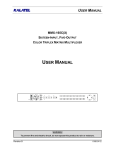
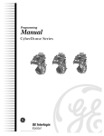
The KTD-405 and KTD-405A packages include a user manual (1036547) and a quick reference guide
(1047307) in addition to the items shown in Figures 1 and 2. Read the manual before beginning
installation and programming so that you can plan your system’s configuration.
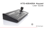
Keypad
Power supply
(N. American: KTD-405)
(European: KTD-405U)
Figure 1.
(1037229)
I/O box
RJ45 control cable
Power cord
(1043406)
(1044203)
(N. American: 1037376)
(European: 1037377)
KTD-405 package contents
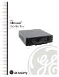
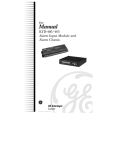
Keypad
Power supply
(N. American: KTD-405A)
(European: KTD-405AU)
Figure 2.
6
(1037229)
I/O box
RJ45 control cable
RJ11 audio cable
Power cord
(1043406)
(1044203)
(D0304A894)
(N. American: 1037376)
(European: 1037377)
KTD-405A package contents
1036547C / December 2003
KTD-405/405A User Manual
2
Operating Modes
OPERATING MODES
The KTD-405 can be programmed to operate in either of two modes: standard Digiplex® or zone
(DVMRe/multiplexer/PTZ control). See Appendix C. Sample System Configurations.
Be aware that the addressing between domes and multiplexers is offset. When setting up and controlling
your cameras in zone mode, refer to Appendix A (Zone Receiver Site Addressing).
2.1
DIGIPLEX MODE
In standard Digiplex mode, the system’s main switching device is a standard matrix switcher. The keypad
can address and control 512 PTZ receiver sites, operate a matrix switcher with 64 monitor outputs, address
and select views from 32 multiplexers, operate up to 32 recorders, and manage access control points.
You can also operate a DVMRe/multiplexer when operating in a hybrid Digiplex mode. This enables the
DVMRe or multiplexer to provide multi-screen views by connecting the output of the unit to an input on the
matrix switcher. Digiplex mode (standard or hybrid) does not require that the DVMRe’s have dedicated
monitors. If you are using CaliburTM units, they must be connected to the keypad’s RS485 control signal;
other brands must be connected to the keypad’s RS422 control signal using a KTD-93 interface. When you
press the zone key, the keypad switches to the zone-mode style of operation (hybrid Digiplex mode), which
enables it to control the DVMRe/multiplexer. See Figure 4. If the zone is assigned to a camera input on the
matrix switcher (done in programming), when you select the zone, the keypad sends a command to the
matrix switcher to call up the assigned input on the active monitor. While in the hybrid Digiplex mode, key
functions are the same as those used during normal zone mode operation, except the esc key, which
returns the keypad to the standard Digiplex mode of operation.
Note: Camera control (PTZ) is disabled while in the hybrid zone mode.
CAMERA 0
MONITOR 1
Figure 3. LCD display of standard Digiplex mode
2.2
ZONE 01
CAM --
DVMRE TRI
MON A ESC=EXIT
Figure 4. LDC display of hybrid Digiplex mode
ZONE MODE
A zone is a remote switching device (multiplexer or DVMRe) that serves a group of cameras. A system
can be divided into as many as 32 zones, and each zone can have from 1 to 32 cameras.
The outputs from the zone’s switching device connect to dedicated monitors directly. Each zone is
assigned a device type (multiplexer or DVMRe) and a size (1 to 32 cameras) and can be assigned a
15-character name.
To call up a camera in a zone you must know the zone number (or name) and the camera number. See
Figure 5 and refer to Appendix A (Zone Receiver Site Addressing).
ZONE -ZONE TITLE
CAMERA -- MONITOR Figure 5. LCD display of zone mode
1036547C / December 2003
7
Installation
3
KTD-405/405A User Manual
INSTALLATION
CAUTION:
Plan your system’s camera and device assignments before installing the system. To help plan
your system, refer to Appendix E. System Planning Guide.
Note: The keypads now ship with an updated I/O box that provides RJ45 ports for the RS485 data line and an RJ11 port for audio.
See section 3.3.6 Connecting New and Old I/O Boxes for connections between the new and old I/O boxes. For connection details
about the old I/O boxes, see Appendix D. Old I/O Box Connections.
3.1
INSTALLATION GUIDELINES
Installation Guidelines
•
Recommended cable types:
Signal
RS485
RS422
Audio
Cable
STP (shielded twisted-pair)
UTP (unshielded twisted-pair)
STP (shielded twisted-pair)
Minimum Size
22 AWG
22 AWG
18 AWG
Note: Refer to device manuals for specific cabling requirements.
8
•
Each keypad requires its own I/O box. You can connect multiple I/O boxes to each other to establish multiple
keypads for controlling one system. For systems that are more complicated than are diagrammed in these
instructions, contact GE Interlogix Technical Support for assistance.
•
The audio and speaker connections are used only with a KTD-405A.
•
Observe polarity when installing the RS422, RS485, and 12 VDC (if not using the provided transformer with
positive polarity center plug) cables.
•
The earth grounds for the I/O boxes are separate from the earth grounds for the RS485 shield.
•
The keypad itself is not grounded.
•
Grounding the I/O box is optional, but it does provide some additional protection against equipment damage
due to electrical storm induced power surges.
•
There must be no current flowing in the shield of shielded cables. Maintain an open circuit (non-continuous
path) for the shield and hold it at the earth ground potential by grounding it at only one location.
•
You can connect the RS485 shield of individual cable segments to each other, but to nothing else. You will
still ground the resulting shield circuit at one location only, despite the number of shield junctions.
•
Each electrical circuit (RS485 segment) must be biased. If keypads reside on separate electrical circuits
(i.e., separated by fiber or Ethernet bridges), then more than one keypad might have the bias switch set to
ON (one for each circuit).
•
The bias is 12-VDC polarity sensitive. If polarity on the power line is reversed, the keypad will not be
damaged but it will not operate correctly.
•
Each electrical segment being terminated must be terminated at each end, and at one location for the bias.
Termination is generally required for the first and last device on a longer line. The termination switches are
located within or on the devices themselves (e.g., keypads and cameras). Refer to device manuals for
termination requirements and methods.
•
Your system should contain only one RS422 chain of devices. Only one KTD-405 keypad should be in that
chain, which can contain any number of other keypads such as KTD-404s.
1036547C / December 2003
KTD-405/405A User Manual
3.2
Installation
BACK PANEL CONNECTIONS
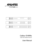
3.2.1 KTD-405 CONNECTIONS
Adhere to all installation guidelines while making connections, including your local codes and those
provided in section 3.1 Installation Guidelines.
RS232 programming port (future use)
I/O box
RS485 and RS422 in/out
Power supply
RS485 termination switch
Power cord
RJ45 control cable*
*GE Interlogix uses two different RJ45
cables. You must use the RJ45 cable
provided with the unit.
Figure 6.
KTD-405 back panel connections
1036547C / December 2003
9
Installation
KTD-405/405A User Manual
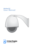
3.2.2 KTD-405A CONNECTIONS
Adhere to all installation guidelines while making connections, including your local codes and those
provided in section 3.1 Installation Guidelines.
RS232 programming port (future use)
RS485 termination switch
I/O box
Audio port
RJ11 audio cable
Power cord
RS485 and RS422 in/out
RJ45 control cable*
Power supply
*GE Interlogix uses two different
RJ45 cables. You must use the
RJ45 cable provided with the unit.
Figure 7.
10
KTD-405A back panel connections
1036547C / December 2003
KTD-405/405A User Manual
3.3
Installation
I/O BOX CONNECTIONS
3.3.1 RJ-CABLE CONNECTIONS
The RJ-cable connections make new installations or additional devices easy to connect. If you are
replacing an old phone-style I/O box in an existing installation, you can use the existing twisted-pair wires
(STP for RS485 and UTP for RS422), if desired. See section 3.3.2 Twisted-Pair Connections.
Adhere to all installation guidelines while making connections, including your local codes and those
provided in section 3.1 Installation Guidelines.
PIN 1:
RS485 shield
(ground one end only;
preferably at mux/DVMRe)
Multiplexer or DVMRe
PIN 3:
RS485A
PIN 6:
RS485B
PINs 2, 4, 5, 7, and 8 are
not connected.
Observe polarity for:
• Audio
• RS422
• RS485
• 12 VDC
(12 VDC transformer
must have a positive
center polarity plug
)
RS485 (optional RJ45 connection*)
(for GE Interlogix DVMRes, multiplexers,
ProBridges, and additional KTD-405 I/O boxes)
RS485 (optional RJ45 RS485 connection*)
(for GE Interlogix DVMRes, multiplexers,
ProBridges, and additional KTD-405 I/O boxes)
KEYPAD (black RJ45 (
) control cable)
Note: The old phone-style I/O box used a silver
) RJ45 keypad cable. You must use the
(
new cable with the new I/O box.
AUDIO (silver RJ11 (
) cable from
keypad (provided only with the KTD-405A))
Crossover cable
Figure 8.
Straight-through cable
*The installer supplies the optional RJ45
RS485 cable(s) with the stated pinouts
(an RS485 connection is also available
on the terminal strip)
RJ-cable connections to the I/O box
1036547C / December 2003
11
Installation
KTD-405/405A User Manual
3.3.2 TWISTED-PAIR CONNECTIONS
The twisted-pair connections are available to connect additional devices or for existing installations where
individual wires were used to connect to the old phone-style I/O box. Easy-to-use RJ-cable connections
are also available on the new I/O box. See section 3.3.1 RJ-Cable Connections.
Adhere to all installation guidelines while making connections, including your local codes and those
provided in section 3.1 Installation Guidelines.
Bias switch
The bias switch maintains an appropriate load on the RS485 line.
Set the bias switch to ON for one keypad in a typical system (any one keypad and
only one keypad). If your system is divided into groups that are separated by fiber or
Ethernet bridges, you must set the bias switch to ON for one keypad in each group.
For safety, use a
tie-wrap to secure
the power cable to
the tie-in.
12 VDC power
(12 VDC transformer
must have a positive
center polarity plug
)
Earth ground (to ground)
RS485 connection*
RS422 IN
(from keypad or
alarm unit, if used)
RS422 OUT
(to switcher or cameras)
Speaker/Shield
(to remote speaker,
if used)
*For multiplexer, DVMRe, or I/O
box of additional keypad (RS485
connections are also available
with the RJ45 connectors)
Figure 9.
12
Observe polarity for:
• 12 VDC
• RS422
• RS485
Wire connections to the I/O box
1036547C / December 2003
KTD-405/405A User Manual
Installation
3.3.3 CONNECTING A MULTIPLEXER OR DVMRe AND DOMES
Adhere to all installation guidelines while making connections, including your local codes and those
provided in section 3.1 Installation Guidelines.
PIN 1 to RS485 shield
(ground one end only)
Observe polarity for:
• RS422
• RS485
• 12 VDC power
(12 VDC transformer
must have a positive
center polarity plug
)
PIN 3 to RS485 A
PIN 6 to RS485 B
Note: PINs 2, 4, 5, 7, and 8 are not
connected.
12 VDC (observe polarity,
if provided transformer not used)
RS485 OUT
(data out to devices such as multiplexers
or DVMRe’s; ground at mux/DVMRe)
KEYPAD IN
(RS422 and RS485 data in from keypad;
RS422 data and power out to keypad)
RS422 IN
(data in from devices such as alarm units,
ASCII converters, or keypads (see guidelines))
RS422 OUT
(data out to devices such as domes,
switchers, or keypads (other than KTD-405s))
Figure 10. Connecting a keypad (KTD-405 shown) to a multiplexer or DVMRe (shown) and domes
1036547C / December 2003
13
Installation
KTD-405/405A User Manual
3.3.4 CONNECTING MULTIPLE KEYPADS WITH RJ45 CABLES
Adhere to all installation guidelines while making connections, including your local codes and those
provided in section 3.1 Installation Guidelines.
Observe polarity for:
• Audio
• RS422
• RS485
• 12 VDC power
(12 VDC transformer
must have a positive
center polarity plug
)
12 VDC (observe polarity, if provided transformer and plug not used)
RS422 IN (data in from devices such as alarm units, ASCII converters, or keypads (see guidelines))
RS422 OUT (data out to devices such as domes, switchers, or keypads (other than KTD-405s))
AUDIO OUT (to speaker and speaker shield)
RS485 OUT (data out to devices such as multiplexers or DVMRe’s; ground at mux/DVMRe)
RS485 to I/O box of additional keypad via RJ45 cable
KEYPAD IN (RS422 and RS485 data in from keypad; RS422 data and power out to keypad)
Note: When using
multiple keypads,
you can connect
CyberDomes and
other receivers to
the RS422 output
from any keypad.
AUDIO IN (from keypad)
PIN 1 to RS485 shield (ground one end only)
PIN 3 to RS485 A
PIN 6 to RS485 B
Note: PINs 2, 4, 5, 7, and 8 are not connected.
Figure 11. KTD-405 and KTD-405A connections via RJ45 cables
14
1036547C / December 2003
KTD-405/405A User Manual
Installation
3.3.5 CONNECTING MULTIPLE KEYPADS WITH STP CABLE
Adhere to all installation guidelines while making connections, including your local codes and those
provided in section 3.1 Installation Guidelines.
12 VDC (observe polarity, if provided transformer and plug not used)
Observe polarity for:
• Audio
• RS422
• RS485
• 12 VDC power
(12 VDC transformer
must have a positive
center polarity plug
)
RS485 to I/O box of additional keypad via STP cable (with floating shield)
RS422 IN (data in from devices such as alarm units, ASCII converters, or keypads (see guidelines))
RS422 OUT (data out to devices such as domes, switchers, or keypads (other than KTD-405s))
AUDIO OUT (to speaker and speaker shield)
RS485 OUT (data out to devices such as multiplexers or DVMRe’s; ground at mux/DVMRe)
Note: When using STP for the RS485 connection between I/O boxes, you can use only one of the two
RJ45 RS485 OUT connections to a multiplexer or DVMRe. This ensures proper termination.
KEYPAD IN (RS422 and RS485 data in from keypad; RS422 data and power out to keypad)
Note: When using
multiple keypads,
you can connect
CyberDomes and
other receivers to
the RS422 output
from any keypad.
AUDIO IN (from keypad)
PIN 1 to RS485 shield (ground one end only)
PIN 3 to RS485 A
PIN 6 to RS485 B
Note: PINs 2, 4, 5, 7, and 8 are not connected.
Figure 12. KTD-405 and KTD-405A connections via STP cable
1036547C / December 2003
15
Installation
KTD-405/405A User Manual
3.3.6 CONNECTING NEW AND OLD I/O BOXES
Adhere to all installation guidelines while making connections, including your local codes and those
provided in section 3.1 Installation Guidelines.
Note: For additional connection details about the old I/O boxes, see Appendix D. Old I/O Box Connections.
Observe polarity for:
• Audio
• RS422
• RS485
• 12 VDC power
(12 VDC transformer
must have a positive
center polarity plug
)
RS485 shield (float)
12 VDC (no polarity on old I/O box)
RJ45 from keypad (RS422 data in from keypad; silver crossover cable for old I/O box)
RS422 IN (data in from devices such as alarm units, ASCII converters, or keypads (see guidelines))
RS422 OUT (data out to devices such as domes, switchers, or keypads (other than KTD-405s))
12 VDC (observe polarity on new I/O box)
RS485 to I/O box of additional keypad
RS485 OUT (data out to devices such as multiplexers or DVMRe’s; ground at mux/DVMRe)
Note: When using STP for the RS485 connection between I/O boxes, you can use only one of the two
RJ45 RS485 OUT connections to a multiplexer or DVMRe. This ensures proper termination.
Note: When using
multiple keypads,
you can connect
CyberDomes and
other receivers to
the RS422 output
from any keypad.
KEYPAD IN (RS422 and RS485 data in from keypad; black straight-through cable for new I/O box)
PIN 1 to RS485 shield (ground one end only)
PIN 3 to RS485 A
PIN 6 to RS485 B
Note: PINs 2, 4, 5, 7, and 8 are not connected.
Figure 13. New to old I/O box connections
16
1036547C / December 2003
KTD-405/405A User Manual
Programming
PROGRAMMING
4
There are three programming modes for the keypad:
! Supervisor Programming Mode: Establishes such essentials as the keypad’s nonvolatile memory, title, and
PTZ-to-KB3 command communication.
! User Programming Mode: Establishes the keypad’s system architecture for operations.
! Remote Device Programming Mode: Enables you to program system devices such as cameras and VCRs.
Refer to the menu keys in Figure 14 and the navigation keys in Table 1 while moving through the
programming menus.
Figure 14. Menu keys (gray keys are available on the KTD-405A only)
Table 1. Navigating the programming menus
Key
!
"
#
$
Function
displays the next menu
displays the previous menu
scrolls up when indicated by ! in the menus
scrolls down when indicated by " in the menus
scrolls right when indicated by # in the menus
scrolls left when indicated by $ in the menus
Joystick
scrolls up, down, left, or right when indicated by !,",$,# in menus
seq
advances menus; or exits menus if held for 3 sec
1st
displays the previous menu
1036547C / December 2003
17
Programming
4.1
KTD-405/405A User Manual
ENTERING THE PROGRAMMING MODES
When you provide power to the unit, the following menu appears:
CAMERA 0
MONITOR 1
1)
To access the programming mode, press and hold the
following menu appears:
key until you hear a tone and the
ENTER PROGRAMMING
CODE:
Note: The ENTER PROGRAMMING CODE menu times out after 5 seconds.
2)
Enter your programming code.
! To enter supervisor menus, press 1-4-7-6-seq and proceed to section 4.2 Supervisor Programming.
! To enter user menus, press 5-7-9-seq and proceed to section 4.3 User Programming.
! To enter remote device programming, press 9-5-1-seq and proceed to section 4.4 Remote Programming.
Note: Menus time out after 4 minutes.
Note: Menus that were not implemented in this release are indicated by two beeps and the following menu:
NOT IMPLEMENTED
4.2
SUPERVISOR PROGRAMMING
From the ENTER PROGRAMMING CODE menu, pressing 1-4-7-6-seq enters the supervisor menus.
The RESET T0 DEFAULTS option erases data in the KTD-405’s nonvolatile memory and reloads factory
values. RESET ALL clears programmed keypad and zone titles; RESET ALL BUT TITLES retains the
zone titles; and RESET CAMERA reinitializes CyberScout cameras so that they find all of their orientation
points.
Note: Access the CyberScout that you want to reset before you enter supervisor programming.
Note: CyberDomes are reset from the CyberDome programming menus. Refer to the CyberDome Programming Manual.
18
1036547C / December 2003
KTD-405/405A User Manual
Programming
Note: Pressing ! forwards you through programming without changing set parameters.
RESET TO DEFAULTS?
(+)=YES (-)=NO
–
NO
"NEXT!
+
1 = RESET ALL BUT TITLES
2 = RESET ALL
3 = CAMERA
If 1 pressed.
!
PARTIAL. ARE YOU SURE?
(+)=YES (-)=NO
"NEXT!
If 2 pressed.
COMPLETE. ARE YOU SURE?
(+)=YES (-)=NO
"NEXT!
If 3 pressed.
RESET CAMERA X ?
ARE YOU SURE? +,YES -,NO
Note: Only CyberScout cameras are reset (i.e.,
reinitialized) when 3 is selected. CyberDomes are reset
from the CyberDome programming menus. Refer to the
CyberDome Programming Manual.
KEYPAD ADDRESS: 99
(01-99)
"NEXT!
INITIALIZING DEFAULTS
PLEASE WAIT
A keypad address is a two-digit number (01 – 99) that distinguishes a keypad from other devices. This
address is automatically assigned when the keypad is first connected into the RS485 communication line.
The address doesn’t change unless you assign a new address or the system configuration changes.
Note: Entering an address that is already assigned displays a menu that reads ADDRESS ALREADY IN USE.
Entering a keypad address or pressing ! displays the following menu:
KB3 PTZ PROTOCOL?
(+)=YES (-)=NO
NO
"NEXT!
If the KTD-405 is being used in a system that needs to communicate PTZ commands to a Calibur
CBR-KB3/J keypad or ProBridge, you must select YES so that the KTD-405 communicates properly with
these devices.
ENABLE REMOTE PRGMG?
YES
(+)=YES (-)=NO
"NEXT!
Enabling remote programming allows the keypad’s user to enter the 9-5-1-seq code for programming
remote devices in the system. If disabled, a tone sounds when the 9-5-1-seq code is entered.
1036547C / December 2003
19
Programming
KTD-405/405A User Manual
KEYPAD TITLE:
Use #,$,
spaces:
, or
(!,",#,$)
"NEXT!
or the joystick to title the keypad. Titles can include A through Z, 0 through 9, and
# or ! Moves from a space to A through Z, to 9 through 0.
$ or " Moves from a space, to 0 through 9, to Z through A.
or # Moves the cursor right.
or $ Moves the cursor left.
A keyboard title can be up to 14 characters. If a keypad is programmed with a title, it can be programmed
with a user-defined four-digit seize control code, which enables a supervisor to seize control of the
keypad’s addressed site. An addressed site is a device such as a camera, DVMRe, or VCR, or an entire
zone if the keypad is programmed in a zone mode.
Note: The next two seize control menus are for future use.
SEIZE CONTROL CODE: 8624
USE NUMBER KEYS
"NEXT!
Entering a four-digit code or ! displays the following menu:
SEIZE CONTROL TIME: 5
(1-10) MINUTES
"NEXT!
The seize control time is the minutes of user inactivity that must elapse before the keypad automatically
exits the seize control state.
LOWEST USER PRGMD PRESET
(01-64) 58
"NEXT!
PTZ presets (0 – 63) are normally stored in the programming menus to protect them from being changed
by the keypad user. The lowest user programmed preset defines which presets are protected. Any
number greater than or equal to the lowest programmed preset can be user-stored during normal
operation by pressing the store key and entering a two-digit preset number, then pressing store again.
If presets 58 through 61 are not protected (default), they work in combination with the aux keys to quickly
store presets aux 1 is 58, aux 2 is 59, aux 3 is 60, and aux 4 is 61. Presets 62 and 63 are used to
and
keys. Preset 0 (home position) can be stored only
store autopan left and right limits using the
in the programming menus.
Note: Pressing the store button and then aux 1,2,3, or 4 prompts you to press store again, which sets the quick store position.
Pressing the find button and then aux 1,2,3, or 4 recalls the quick store position.
20
1036547C / December 2003
KTD-405/405A User Manual
Programming
4.2.1 SOFT KEY REPROGRAMMING
From the supervisor programming mode you can reprogram any of the soft keys with any of the available
commands. See Appendix B. Reprogrammable Keys and Commands for a list of the keys and commands.
Note: Pressing and holding the seq key returns you to the normal operating display, except on displays where esc is required to exit.
1)
Beginning at the normal operating display, enter the supervisor programming mode by pressing and
key. Quickly move to the next step after the keypad beeps and the code entry
holding the
display appears.
CAMERA 0
MONITOR 1
Normal operating display
2)
At the code entry display, enter the access code for the supervisor menus by pressing the 1, 4, 7, 6,
and seq keys. The display will automatically advance to the next display.
ENTER PROGRAMMING
CODE:
Code entry display
3)
Press the ! key (for NEXT) until the PROGRAM SOFT KEYS display appears.
4)
At the PROGRAM SOFT KEYS display, press the ! side of the zoom, focus, or iris key.
PROGRAM SOFT KEYS?
(+)=YES (-)=NO
_
"NEXT!
PROGRAM SOFT KEYS display
5)
At the PRESS KEY TO PROGRAM display, press any of the available reprogrammable keys (see
Appendix B. Reprogrammable Keys and Commands).
PRESS KEY TO PROGRAM:
ESC=EXIT
PRESS KEY TO PROGRAM display
6)
At the command selection display, use the joystick (or the & and # keys) to scroll up and down
through the list of commands until the desired command appears. The commands are listed in
key ('─ on the display) to save the selected command for
alphabetical order. Then press the
the reprogrammed soft key.
Note: Pressing the '' key returns you to the PRESS KEY TO PROGRAM display.
SLW/STOP
-#
(())
('-)=SAVE
STABILIZ
''BACK
Command selection display
1036547C / December 2003
21
Programming
7)
KTD-405/405A User Manual
At the confirm command selection display, press the ! side of the zoom, focus, or iris key to
confirm the assignment of the command for the key or press '' to return to the PRESS KEY TO
PROGRAM display.
SLW/STOP
(+)=CONFIRM
-#
STABILIZ?
''BACK
Confirm command selection display
8)
The KEY HAS BEEN PROGRAMMED display flashes briefly, then you are returned to the PRESS
KEY TO PROGRAM display. If you have no further soft keys to reprogram, press esc to exit to the
PROGRAM SOFT KEYS display. To reprogram additional keys, go to step 5.
KEY HAS BEEN PROGRAMMED
KEY HAS BEEN PROGRAMMED display
9)
PRESS KEY TO PROGRAM:
ESC=EXIT
PRESS KEY TO PROGRAM display
At the PROGRAM SOFT KEYS display, press and hold the seq key to return to the normal
operating display.
PROGRAM SOFT KEYS?
(+)=YES (-)=NO
_
"NEXT!
PROGRAM SOFT KEYS display
CAMERA 0
MONITOR 1
Normal operating display
Pressing the ! side of the zoom, focus, or iris key returns you to the PRESS KEY TO PROGRAM menu.
PRESS KEY TO PROGRAM:
ESC=EXIT
PRESS KEY TO PROGRAM display
Pressing ! or the – side of the zoom, focus, or iris key takes you to the CHANGE ACCESS
CODES menu.
Note: The following menu is for future use.
CHANGE ACCESS CODES?
(+)=YES (-)=NO
"NEXT!
CHANGE ACCESS CODES display
Pressing – or ! takes you to the OPERATING MODE menu. See section 4.3 User Programming.
22
1036547C / December 2003
KTD-405/405A User Manual
4.3
Programming
USER PROGRAMMING
From the ENTER PROGRAMMING CODE menu, pressing 5-7-9-seq enters the user menus:
OPERATING MODE:
(!,")=SELECT
DIGIPLEX
"NEXT!
The operating mode defines the keypad’s system architecture. The choices are DIGIPLEX, which is
conventional system operation, and ZONE, which divides the system into 32 zones.
Selecting DIGIPLEX takes you to the standard Digiplex menus, section 4.3.1 Standard Digiplex Menus.
Selecting ZONE takes you to the zone menus, section 4.3.2 Zone Menus. Refer to Appendix A (Zone
Receiver Site Addressing).
4.3.1 STANDARD DIGIPLEX MENUS
The next five menus are used to set the system’s size to restrict the user from calling up unused
addresses. They also define the maximum number of keystrokes used to automatically select an address.
For example, if there are fewer than 10 cameras in the system, the keypad user can select each camera
site with only one key press.
SYSTEM SIZE:
(CAMERAS) 511
"NEXT!
Enter the highest camera number in your system.
SYSTEM SIZE:
(MONITORS) 64
"NEXT!
Enter the highest monitor number in your system.
SYSTEM SIZE:
(MPLXS)
32
"NEXT!
Enter the highest multiplexer number in your system.
SYSTEM SIZE:
(DSR/VCR) 32
"NEXT!
Enter the highest VCR number in your system.
SYSTEM SIZE:
(PRESETS) 63
"NEXT!
Enter the highest preset number.
1036547C / December 2003
23
Programming
KTD-405/405A User Manual
The following access menus are used to restrict the keypad from addressing specified sites in the system.
Note: The access menus enable you to allow access for each camera, monitor, DSR/VCR, and multiplexer. To move from one type
of access menu to another, press ! or ".
CAMERA 000 ACCESS?
(+)=YES (-)=NO
YES
"NEXT!
MONITOR 01 ACCESS?
(+)=YES (-)=NO
YES
"NEXT!
Note: If you do not want to interrupt viewing at another keypad, program the keypad to address only the monitors within its view.
DSR/VCR 01 ACCESS?
(+)=YES (-)=NO
YES
"NEXT!
Pressing + displays the following menu:
VCR 01 MATRIX INPUT:
000 (0=NONE)
"NEXT!
The VCR output can be assigned an input number on the matrix switcher. When a VCR is called, the
matrix switcher switches to the assigned input.
Enter a number from 1 through 511, or enter 0 for NONE.
MPLX 01 ACCESS?
(+)=YES (-)=NO
–
YES
"NEXT!
"NEXT!
By default, the selected monitor number
corresponds to the number of the matrix switcher
output to which it is connected. For example, if
monitor 12 appears in the keypad’s display
window and a camera selection is made, the
monitor that is connected to output 12 of the
matrix switcher switches to that camera.
In some applications, you might prefer to have the
monitors numbered as 1, 2, 3, etc., instead of
using the matrix switcher output number. To do
this, subtract the desired monitor number from the
matrix switcher output number and enter the
difference as the monitor offset.
24
MPLX01 BRAND
(!,")=SELECT
DVMRe DUP
"NEXT!
Use # or $ or the joystick to
scroll through multiplexer
manufacturers.
!
MONITOR OFFSET
NUMBER: 0
+
!
MPLX 01 MATRIX INPUT?
000 (0=NONE)
"NEXT!
If the DVMRe/multiplexer’s output(s) is
connected to an input on a matrix switcher,
enter the input number (1 – 511, or 0 for
none).
SELECT MAX OUTPUTS:
02
(!,")=SELECT
"NEXT!
Enter the number of outputs (1 – 5) connected
to the matrix switcher. This returns you to the
MPLX XX ACCESS menu.
Note: Outputs must be connected in sequential order to
inputs if more than one output from a single DVMRe/mux
is used.
1036547C / December 2003
KTD-405/405A User Manual
Programming
For example, a keypad has a monitor that is connected to matrix switcher output 12. To enable the monitor
to be addressed as monitor 1, subtract 1 from 12 and enter the difference (11) as the monitor offset.
In this example, if more than one monitor were to be controlled from the keypad, additional monitors
would be connected to matrix switcher outputs 13, 14, 15, etc., and would be controlled as monitor 2,
monitor 3, monitor 4, etc.
Note: The keypad will deny any monitor offset number that conflicts with the monitor system size and the monitor access
programming choices that have been made.
ANNUNCIATION?
(+)=YES (-)=NO
NO
"NEXT!
When annunciation is enabled, the keypad displays the 1st, 2nd, and 3rd call-in queue on the LCD and can
store up to 32 call-in requests.
Pressing + and then ! displays the following menu:
CALL TONE TYPE? MULTIPLE
(!,")=SELECT
"NEXT!
In the annunciation mode, the keypad produces a tone on a call-in request or alarm. This sound can be
set to one frequency (single) or to warble between two frequencies (multiple).
SPOT MONITOR NUMBER:
0
(0=UNASSIGNED)
"NEXT!
When a spot monitor number is assigned, pressing the 1st key displays the first site number in the
annunciation queue on the spot monitor, and the keypad automatically addresses control to that monitor.
4.3.2 ZONE MENUS
Remember that the addressing between domes and multiplexers is offset. When setting up and
controlling your cameras in zone mode, refer to Appendix A (Zone Receiver Site Addressing).
OPERATING MODE:
(!,")=SELECT
ZONE
"NEXT!
Selecting ZONE in the OPERATING MODE menu displays the following menu:
LCD DISPLAY LABEL:
(!,")=SELECT
ZONE
"NEXT!
This menu enables you to change the hub device label displayed on the LCD during normal operation.
Label choices are ZONE, MPLX, DVMR, TERR, BLDG, FLR, DEPT, STA, SITE, or AREA. ZONE is the
default label.
1036547C / December 2003
25
Programming
KTD-405/405A User Manual
ENTER ZONE ADDRESS:
01
(01-32)
"NEXT!
Pressing ! takes you to the ZONE XX ACCESS menu, page 27.
Entering a two-digit zone address displays the following menu:
ZONE 01 TITLE:
Use #,$,
spaces:
, or
(!,",#,$)
"NEXT!
or the joystick to title the zone. Titles can include A through Z, 0 through 9, and
# or ! Moves from a space to A through Z, to 9 through 0.
$ or " Moves from a space, to 0 through 9, to Z through A.
or # Moves the cursor right.
or $ Moves the cursor left.
Zone titles enable you to identify which zone is being addressed (e.g., Building 248, Headquarters). A
zone title can be up to 15 characters.
Note: When you enter or change a zone title from the 1-4-7-6-seq code, you have the option of sending the title to all keypads in the
system:
SEND TO ALL KEYPADS?
(+)=YES (-)=NO
"NEXT!
ZONE 01 HUB:
(!,")=SELECT
DVMRe DUP
"NEXT!
A hub is the main recording device in a zone. Hub choices are DVMRe DUP, CALIBUR MMX, TRIPLEX
MUX, DUPLEX MUX, SIMPLEX MUX, MATRIX SWCH, and DVMRe TRI.
The next two menus are used to set the system’s size to restrict the user from calling up unused
addresses. They also define the maximum number of keystrokes used to automatically select an address.
For example, if there are fewer than 10 monitors in the system, the keypad user can select each monitor
site with only one key press.
Note: Zone outputs and inputs depend on the hub you selected in the previous menu.
ZONE 01 MON. OUTPUTS:
01 TO 02
"NEXT!
Enter the number of monitor outputs you have for this zone (1 – 32).
ZONE 01 CAM. INPUTS:
16
(!,")=SELECT
"NEXT!
Zone size choices are 4, 9, 10, 16, 32, and 64, depending on the hub (up to 64 for matrix switchers, up to
32 for multiplexers, and up to 16 for all others).
26
1036547C / December 2003
KTD-405/405A User Manual
Programming
The following system access menus are used to restrict the keypad from addressing specified sites in the
system:
ZONE 1 CAM 01 ACC?
(+)=YES (-)=NO
YES
"NEXT!
ZONE 1 MON 1 ACC?
(+)=YES (-)=NO
YES
"NEXT!
ZONE 01 RECORDER ACC? YES
(+)=YES (-)=NO
"NEXT!
Note: If you are using MMX or Triplex without a VCR attached through submacros, deny zone recorder access.
This menu returns you to the ENTER ZONE ADDRESS menu. From the ENTER ZONE ADDRESS menu,
you can program all zones. When you have finished programming all zones, pressing ! from the ENTER
ZONE ADDRESS menu displays the following menu:
ZONE 01 ACCESS:
(+)=YES (-)=NO
YES
"NEXT!
Pressing + or – enables you to allow or deny access for each zone.
Pressing ! displays the following menu:
Note: The following menu is for future use.
ANNUNCIATION?
(+)=YES (-)=NO
NO
"NEXT!
When annunciation is enabled, the keypad displays the 1st, 2nd, and 3rd call-in/alarm on the LCD and
stores up to 32 call-in requests.
Pressing + and then ! displays the following menu:
CALL TONE TYPE? MULTIPLE
(!,")=SELECT
"NEXT!
In the annunciation mode, the keypad produces a tone on a call-in request or alarm. This sound can be
set to one frequency (single) or to warble between two frequencies (multiple).
SPOT MONITOR NUMBER:
0
(0=UNASSIGNED)
"NEXT!
When a spot monitor number is assigned, pressing the 1st key displays the first site number in the
annunciation queue on the spot monitor, and the keypad automatically addresses control to that monitor.
1036547C / December 2003
27
Programming
4.4
KTD-405/405A User Manual
REMOTE PROGRAMMING
From the ENTER PROGRAMMING CODE menu, pressing 9-5-1-seq enables you to program system
devices such as cameras and VCRs.
Note: Remote programming can be denied by a supervisor.
1=SWITCHER/MPLX
3=CAMERA/RCVR
2=ALARMS
EXIT!
Note: To program an auxiliary device, refer to the relevant manual.
4.4.1 SWITCHER/MPLX
1=440
2=CALIBUR
3=340/348
"BACK
4.4.1.1 440 (PRESS 1)
ENTER MONITOR NUMBER:
(1-64)
"BACK
SEE MONITOR FOR MENUS
HOLD SEQ <3 SEC> TO EXIT
4.4.1.2 CALIBUR (PRESS 2)
ENTER CALIBUR ADDRESS:
(1-32)
"BACK
SEE MONITOR FOR MENUS
HOLD SEQ <3 SEC> TO EXIT
4.4.1.3 340/348 (PRESS 3)
ENTER MONITOR NUMBER:
(1-64)
"BACK
SEE MONITOR FOR MENUS
HOLD SEQ <3 SEC> TO EXIT
4.4.2 ALARMS
SEE MONITOR FOR MENUS
HOLD SEQ <3 SEC> TO EXIT
4.4.3 CAMERA/RCVR
1=CYBERDOME
3=AUXILIARY
2=PTZ
"BACK
Note: Auxiliary (3) is for future use.
28
1036547C / December 2003
KTD-405/405A User Manual
Programming
If you are in standard Digiplex mode, pressing 1 prompts you to enter a CyberDome site number:
ENTER CYBERDOME SITE
NUMBER
"BACK
SEE MONITOR FOR MENUS
HOLD SEQ <3 SEC> TO EXIT
If you are in a zone mode, pressing 1 prompts you to enter a CyberDome camera number within the
current zone:
Note: You must select the zone before entering programming mode.
ENTER ZONE 1
NUMBER__
CAMERA
"BACK
SEE MONITOR FOR MENUS
HOLD SEQ <3 SEC> TO EXIT
4.4.4 CYBERSCOUT SHADOWTOUR
Note: Refer to the CyberDome Programming Manual for the programming of CyberDome tours.
To program a CyberScout ShadowTour™:
1)
Beginning at the normal operating display, enter the ShadowTour programming mode by pressing
and holding the esc key, then pressing the tour key.
CAMERA 0
MONITOR 1
Normal operating display
2)
At the PROGRAM SHADOW TOUR display, press the ! side of the zoom, focus, or iris key to start
recording a ShadowTour. Quickly move to the next step after the keypad beeps and the end
Shadow Tour programming display appears.
Note: Pressing the ",!, or – keys will return you to the normal operating display.
PROGRAM SHADOW TOUR?
_
(+)=YES (-)=NO
"NEXT!
PROGRAM SHADOW TOUR display
3)
Begin the manual operation sequence you want to record as your ShadowTour.
4)
At the END SHADOW TOUR PROGRAMMING display, press the esc key to stop recording the
ShadowTour.
Note: The keypad is still recording your manual operation even though the END SHADOW TOUR PROGRAMMING display
returns to the normal operating display after a few seconds. Continue your sequence and press esc to stop recording.
PRESS <ESC> TO END
SHADOW TOUR PROGRAMMING
END SHADOW TOUR PROGRAMMING display
Your ShadowTour is now available for use. Follow the keypad’s instructions for activating the
ShadowTour. See Table 2.
1036547C / December 2003
29
Operation
KTD-405/405A User Manual
OPERATION
5
Remember that the addressing between domes and multiplexers is offset. When setting up and
controlling your cameras in zone mode, refer to Appendix A (Zone Receiver Site Addressing).
Table 2. Normal key functions
Key
Normal Function
mon
with number keys, selects active monitor from matrix switcher or multiplexer
view
works in two ways, depending on the type of multiplexer or DVMRe you are
addressing:
for duplex DVMRe’s and most multiplexers, pressing view steps selected
monitor through programmed multiscreen views (if view is pressed and held for
5 sec, the keypad will broadcast a command to all CyberDomes to display their
site address and zone mode; Calibur devices will display their address; status
disappears when the key is released)
for triplex DVMRe’s and some brands of multiplexers, pressing view with
number keys selects multiscreen views (e.g., view, 2 calls up 2 x 2 view, and
view, 4 calls up 4 x 4 view)
zone
with number keys, selects a zone
aux 1
default assignment sends “open” command to selected camera address
aux 2
close
aux 3
stop
aux 4
last for KTD-405; talk for KTD-405A
seq
alarm
toggles active monitor between the alarm on and alarm off modes;
calls up help menus when remotely programming matrix switcher and
CyberDome
tour
with number keys 1 – 4 (1 only, for CyberScout), places PTZ receiver in tour
mode; or, if pressed and held for 3 sec, keypad beeps and sends an autopan
command to PTZ receiver
store
with number keys, sets presets and autopan limits for selected camera;
accesses sequence programming for Calibur multiplexers
find
with number keys, selects PTZ position saved by the previous store command
for selected camera site
+zoom -
controls the zoom function on selected receiver site’s motorized zoom lens
+focus -
controls the focus function on selected receiver site’s motorized zoom lens;
disables the auto focus feature on CyberDome
+iris -
controls the iris function on selected receiver site’s motorized zoom lens
esc
with number keys, clears alarms and clears number entry
1st
selects earliest of pending annunciations
auto focus
30
activates a sequence tour on the active monitor (Calibur multiplexers only)
places selected CyberDome camera in auto focus mode
1036547C / December 2003
KTD-405/405A User Manual
Key
Normal Function
0–9
selects camera (selects any numeric entry following other keys)
Operation
places selected DSR, DVMRe, or VCR in fast forward mode
toggles selected multiplexer’s full-screen picture between normal and 2X
magnification
locates video on selected DVMRe
places selected DSR, VCR, or DVMRe in pause mode
places selected DSR, VCR, or DVMRe in play mode
places selected DSR, VCR, or DVMRe in record mode
places selected monitor’s DSR, VCR, or DVMRe in fast reverse mode
advances selected DSR or DVMRe one frame forward in pause mode
steps selected DVMRe one frame backward in pause mode; selects reverse
play in play mode
places selected monitor’s DSR, VCR, or DVMRe in stop mode;
exits play mode in multiplexers
esc plus
(dsr/vcr)
5.1
with number keys, addresses remote recording device
STANDARD DIGIPLEX MODE
5.1.1 LCD NORMAL SCREEN
The LCD displays the current camera number and the current monitor number:
CAMERA 0
MONITOR 1
5.1.1.1 SYSTEM INFORMATION MENUS
In the LCD normal screen, pressing and holding mon displays the system information menus. The menus
display the keypad’s address, version, and system size setting.
1036547C / December 2003
31
Operation
KTD-405/405A User Manual
To navigate through the three menus, use " and !. To exit the system information menus, press "
from the first menu or press esc.
KEYPAD ADDRESS:
KEYPAD 99
99
VERSION 1.0.14
AUG 6 2002 10:54:13
"NEXT!
Maximum number of cameras
Maximum number of monitors
Maximum number of multiplexers
Maximum number of recorders
CAM MN MX RC PS QS MO AT
511 64 32 32 63 58 00 W
Annunciation and Tone
Monitor offset
Lowest user-programmable preset (quick set)
Highest preset
5.1.1.2 HELP MENU
To display the HELP menu:
At the normal operating display, consecutively press, briefly hold, and release the esc and mon keys.
Note: The help menu times out in 10 seconds.
HELP MODE:
PRESS KEY
->
ENTER=EXIT
SEE FUNCTION
To display a key’s default function:
At the HELP menu, press a key. See Table 2 for a list of keys and their functions.
To display a key’s shifted (secondary) function:
At the HELP menu, press esc and a key. See Table 3 for a list of keys and their shifted functions.
To exit the HELP menu, press
.
Table 3. Shifted key functions
Key
Shifted Function
Key
Shifted Function
mon
help
vol ▲
slow
zone
group
vol ▼
fast
1st
macro
joystick left
auto focus
autopan
joystick up
dsr/vcr
alt
joystick right
aux 1
unlock
live
32
1036547C / December 2003
KTD-405/405A User Manual
Operation
aux 2
lock
light
aux 3
flip
site down
aux 4
stabilize
joystick down
seq
function
site up
store
group
home
find
step
0 lux
face
card
+ zoom -
volume up/down
badge
door 1
+ iris -
backlight bright/dim
over
door 2
5.1.2 SELECTING A CAMERA
When a camera is selected, a command is sent to the switching device to call that camera to the active
monitor. There are two camera-selection methods:
! Enter the camera number including preceding zeroes (e.g., if you have tens of cameras, enter 01 for
camera 1; if you have hundreds of cameras, enter 001 for camera 1).
! Enter the camera number directly (omitting preceding zeroes), and then press
.
5.1.3 CONTROLLING A CAMERA
5.1.3.1 PTZ
Pan, tilt, and zoom are controlled by the joystick. Zoom is also controlled by the + zoom - key.
To pan, move the joystick left or right. To tilt, move the joystick up or down. To zoom, twist the joystick
knob clockwise or counterclockwise.
5.1.3.2 FOCUS
For auto focus, press the auto focus key. To focus manually, use the + focus - key.
5.1.3.3 IRIS
The iris is controlled by the + iris -key; + opens the iris and - closes the iris.
1036547C / December 2003
33
Operation
KTD-405/405A User Manual
5.1.3.4 SETTING A PRESET
1)
Position the camera.
2)
Press store.
3)
Enter the preset number using the number keys, or aux 1, 2, 3, or 4 for presets 58 through 61.
Note: Presets 62 and 63 cannot be set using the number keys; they can be set by using the
4)
and
keys only.
Press store.
5.1.3.5 SETTING AUTOPAN LIMITS
Left Autopan Limit
To set the limit for the left turn-around point of the camera’s back and forth motion, as wells as the tilt and
zoom positions for the autopan, perform the following:
1)
Position the camera at the desired left limit.
2)
Tilt and zoom the camera into the desired position.
3)
Press store.
Note: Do not attempt to enter a preset number. The preset number 62 is reserved for the left autopan limit and is
automatically entered when you perform step 5.
4)
Press
.
5)
Press store again. The Store Preset Number displays on the keypad.
Right Autopan Limit
To set the limit for the right turn-around point of the camera’s back and forth motion, perform the
following:
1)
Position the camera at the desired right limit and press store.
Note: Do not attempt to enter a preset number. The preset number 63 is reserved for the right autopan limit and is
automatically entered when you perform step 3.
.
2)
Press
3)
Press store again. The Store Preset Number displays on the keypad.
5.1.4 SELECTING A MONITOR
The monitor selection is internal to the keypad; no command is sent to the switcher. There are two
monitor-selection methods:
1)
Press the mon key.
2)
Enter the monitor number including any preceding zeroes, or
.
Enter the monitor number directly, then press
34
1036547C / December 2003
KTD-405/405A User Manual
Operation
5.1.5 OPERATING GROUP SWITCHING ON DIGIPLEX IV SWITCHERS
In Digiplex mode, while pressing esc, pressing zone displays the following menu:
ENTER MONITOR GROUP
(1-64)__
OR <TOUR>
TOUR
Entering a number from 1 through 64
calls up that group of cameras, or press tour
to enter a group sequence tour.
ENTER GROUP SEQUENCE
(1-12)__
Entering a number from 1 through 12
initiates that group sequence.
5.1.6 CONTROLLING A DVMRe/MULTIPLEXER
When you press the zone key, the keypad switches to the hybrid zone mode. In this mode, the keypad
can control a DVMRe/multiplexer. Key functions are the same as those used during normal zone mode
operation, except the esc key, which returns the keypad to the standard Digiplex mode. See Table 4.
Note: Camera control (PTZ) is disabled while in the hybrid zone mode.
5.1.7 CONTROLLING A RECORDING DEVICE
When a recording device is selected, it can be controlled by the keypad (see Table 4 and Appendix A.
Zone Receiver Site Addressing).
Table 4. Controlling a recording device
Control
%
$
&
#
!
"
Function for DSR/VCR
Function for DVMRe
starts record mode
starts record mode
starts playback mode
starts playback mode
stops record or playback mode
stops record or playback mode
pauses playback
pauses playback or live view
fast forwards playback
fast forwards playback
rewinds playback
rewinds playback
forwards playback by frame (action
depends on DSR/VCR)
in reverse: shifts play direction to forward
in pause mode: steps playback forward one
frame
reverse playback (action depends
on DSR/VCR)
playing forward: shifts play direction to
reverse
in pause mode: steps playback in reverse one
frame
zooms image to 2X magnification (toggle)
calls up screen to search for specific recording
puts DVMRe in playback mode
1036547C / December 2003
35
Operation
KTD-405/405A User Manual
Control
Joystick
Function for DSR/VCR
twisting right: steps forward at a
variable rate
twisting left: steps in reverse at a
variable rate
Function for DVMRe
in play or pause mode
right: fast forwards
left: rewinds
up: skips forward approximately 15 sec
down: skips backward approximately 15 sec
twisting right: steps forward at a variable rate
twisting left: steps in reverse at a variable rate
return to center: resumes pause mode
with 2X magnification on
right: pans right
left: pans left
up: pans up
down: pans down
5.2
ZONE MODE
5.2.1 LCD NORMAL SCREEN
The LCD displays the zone number and title on the top line and the current camera and monitor numbers
on the bottom line:
ZONE -ZONE TITLE
CAMERA -- MONITOR -
5.2.2 SELECTING A ZONE
1)
Press zone
2)
Enter a zone number.
The LCD displays the zone number and title, which is created during programming.
5.2.3 SELECTING A CAMERA
! Enter the camera number including any preceding zeroes (e.g., if you have tens of cameras, enter
01 for camera 1; if you have hundreds of cameras, enter 001 for camera 1), or
! Enter the camera number directly (omitting preceding zeroes), then press
.
5.2.4 CONTROLLING A CAMERA
5.2.4.1 PTZ
Pan, tilt, and zoom are controlled by the joystick. Zoom is also controlled by the + zoom - key.
To pan, move the joystick left or right. To tilt, move the joystick up or down. To zoom, twist the joystick
knob clockwise or counterclockwise.
36
1036547C / December 2003
KTD-405/405A User Manual
Operation
5.2.4.2 FOCUS
For auto focus, press the auto focus key. To focus manually, use the + focus - key.
5.2.4.3 IRIS
The iris is controlled by the + iris - key; + opens the iris, - closes the iris.
Note: Refer to the CyberDome manual for additional operation on some CyberDome models.
5.2.5 SELECTING A MONITOR
1)
Press the mon key.
2)
Enter the monitor number including any preceding zeroes, or
Enter the monitor number directly, and then press
.
5.2.6 SELECTING AND CONTROLLING A DVMRe/MULTIPLEXER
When a zone is active, the corresponding DVMRe/multiplexer can be controlled by the keypad. See
Table 5.
Table 5. Controlling a multiplexer
Control
Function for Multiplexer
Function for DVMRe
starts record mode
starts record mode
starts playback mode (if multiplexer
has an attached DSR/VCR, a play
command is sent to the multiplexer
and the VCR)
starts playback mode
stops playback or record mode
stops playback or record mode
pauses live picture; pauses playback
pauses playback or live view
toggles image between normal and
2X magnification (joystick moves
view)
zooms image to 2X magnification (toggle)
calls up screen to search for specific
recording
puts DVMRe in playback mode
1036547C / December 2003
37
Operation
KTD-405/405A User Manual
Control
Function for Multiplexer
when attached to a DSR/VCR in
pause mode
twisting right: steps forward at a
variable rate
twisting left: steps in reverse at a
variable rate
in any mode with 2X magnification
right: pans right
left: pans left
up: pans up
down: pans down
Joystick
Function for DVMRe
in play or pause mode
right: fast forwards
left: rewinds
up: skips forward approximately 15 sec
down: skips backward approximately 15
sec
twisting right: steps forward at a variable
rate
twisting left: steps in reverse at a
variable rate
return to center: resumes pause mode
with 2X magnification on
right: pans right
left: pans left
up: pans up
down: pans down
When multiplexer is attached to a VCR
!
"
fast forwards playback
fast forwards playback
rewinds playback
rewinds playback
in pause mode, steps forward one
frame
in reverse: shifts play direction to forward
in pause mode: steps playback forward
one frame
in pause mode, steps in reverse one
frame
playing forward: shifts play direction to
reverse
in pause mode: steps playback in
reverse one frame
To enter a Calibur DVMRe’s/multiplexer’s programming menus, perform the following steps:
1)
Enter the remote programming mode:
a) Press and hold
.
b) Press 9-5-1-seq.
2)
Select 1, switcher/multiplexer.
3)
Select 2, Calibur.
4)
Enter the Calibur address.
5)
Press
6)
Enter the Calibur password.
.
To navigate the DVMRe/multiplexer programming menus, see Table 6.
38
1036547C / December 2003
KTD-405/405A User Manual
Operation
Table 6. Navigating Calibur menus
Control
Joystick
!
"
Function
moves left and right within menu options;
can be used to move up and down within the menu options
makes selections
backspaces out of selections;
exits the programming menus if pressed in the main menu
moves up within menu options
moves down within menu options
moves right within menu options
moves left within menu options
interchangeable with !
esc
interchangeable with "
5.2.7 CONTROLLING A RECORDING DEVICE
When a zone is active, the corresponding recording device can be controlled by the keypad. See Table 7.
Table 7. Controlling a recording device
Control
Function
starts record mode
starts playback mode
stops record or playback mode
pauses playback
fast forwards playback
rewinds playback
in pause mode, steps recording forward frame by frame
in pause mode, steps recording in reverse frame by frame
Joystick
in pause mode
twisting right: steps forward by frame
twisting left: steps in reverse by frame
1036547C / December 2003
39
Operation
KTD-405/405A User Manual
5.2.8 PROGRAMMING A DVMRe/MULTIPLEXER CAMERA SEQUENCE
If you are using a Calibur DVMRe/multiplexer, you can set a camera sequence:
1)
Press store.
2)
Press seq.
The following menu appears:
ENTER SEQUENCE CAMERA
" CANCEL
DONE !
3)
Enter the number of the first camera in the sequence.
4)
Wait the amount of time you want between cameras, then press the next camera in the sequence.
5)
Repeat step 4 until all cameras in the sequence have been entered.
6)
Press !.
Note: Pressing seq toggles between sequencing and not sequencing.
5.3
AUDIO
5.3.1 ANNUNCIATION
When a keypad is programmed for site annunciation, it stacks as many as 32 call-in requests in the order
in which they are received. The numbers of the first three sites appear in the keypad’s display window.
CAM 000
MON 01
1ST
001
2ND
123
3RD
345
Normal operating display with annunciation
To call up the first site:
Press the 1st key. The site will be removed from the queue and the waiting requests will move up in order.
To call up any site in the queue:
Press 0 through 9 to enter a site number. The site will be removed from the queue and the waiting
requests will move up on order.
Note: When an annunciation call is received, a tone sounds every 15 seconds until the call is cleared by an operator. In multiplexer
mode, the tone sounds every 5 seconds.
40
1036547C / December 2003
KTD-405/405A User Manual
Operation
5.3.2 TWO-WAY AUDIO
To establish two-way audio communication with a site:
1)
Press 0 through 9 to enter a site number.
2)
Use the vol (volume) keys to adjust the audio level.
3)
Press aux 4 to talk to the site. The aux 4 key on the audio-version of the keypad automatically
defaults to talk mode.
Note: When using a KTD-336 audio converter, set the attenuation jumpers to the ON position. See Figure 15. The attenuation
jumpers are located on the audio/IO card, which is attached to the keypad’s base plate. When not using an audio converter, leave
the attenuation jumpers in their default OFF position.
Back of keypad
(with cable ports)
Attenuation
jumpers
Front of keypad
Figure 15. Audio/IO card with attenuation jumpers
1036547C / December 2003
41
Troubleshooting
6
KTD-405/405A User Manual
TROUBLESHOOTING
Adhere to all installation guidelines while making connections, including those provided in section
3.1 Installation Guidelines.
Problem
No control of cameras or
DMVRe
Probable Cause
Solution
Incorrect usage
Make sure that you are in zone mode while trying to
control cameras through a DVMRe.
Incorrect wiring
Verify that:
• The correct type of wiring (STP or UTP) is being
used for the different signals.
• All wires are in good condition.
• All cabling and pinout connections are made
according to directions (observing polarity, when
necessary).
• Equipment is properly terminated.
• Cables are properly grounded.
See installation guidelines and diagrams in section
3 Installation.
Incorrect wiring of dome inputs
or incorrect zone addressing
(camera addressing starts at 0
in zone mode)
The address of the camera has to be one less than
the input on the DVMRe. Readdress the cameras or
move the coaxial connections up one input on the
DVMRe.
See Appendix A. Zone Receiver Site Addressing.
DVMRe and/or keypad
readiness
Cycle the power on the DVMRe and keypad.
Not connecting to DVMRe
Incorrect programming
If the DMVRe is a triplex, ensure that the hubs are set
to triplex in the zone programming.
Loss of control between
keypads
Keypad positioned incorrectly
on the RS422 control line with
a switcher and data merger
Refer to the keypad, switcher, and data merger
installation instructions and correct wiring along
RS422 control line. With the KTD-405 keypad, the
units should be in line in the following order: keypad,
data merger, and switcher.
Unclear audio on audio
keypads
Incorrectly set jumpers or
faulty KTD-336
Ensure that the attenuation jumpers are set according
to section 5.3.2 Two-Way Audio.
If a KTD-336 is present, ensure that its relays are not
clicking. If they are, contact Technical Support.
42
1036547C / December 2003
KTD-405/405A User Manual
No or poor control of dome
Troubleshooting
Poor voltage or resistance on
the data line
If the wiring, addressing, and termination of the
camera and keypad are all correct:
• Verify that the voltage along the RS422 data line
reads approximately 1.5 VDC and that it drops
when a command is sent. If it isn’t, check the
power line.
• Verify that the resistance across the RS422 data
line is between 95 and 125 ohms. If it isn’t, contact
GE Interlogix Technical Support.
1036547C / December 2003
43
Appendix A. Zone Receiver Site Addressing
KTD-405/405A User Manual
APPENDIX A. ZONE RECEIVER SITE ADDRESSING
Each receiver has a DIP switch used to assign its site address. In zone operation, to determine the
receiver site address, see Table A1, Table A2, and Figure A1 and perform the following:
1)
Determine which position values must be added together to equal the site number.
2)
Place the switches that correspond to those values in the ON position.
Table A1. Dip switch positions and equivalent values
DIP switch position number
1
2
3
4
5
6
7
8
9
Equivalent value
1
2
4
8
16
32
64
128
256
Table A2. Receiver site addressing values by zone
Zone Number
Camera
Input
1
2
3
4
5
6
7
8
9
10
11
12
13
14
15
16
1
2
3
4
5
6
7
8
9
10
11
12
13
14
15
16
17
18
19
20
21
22
23
24
25
26
27
28
29
30
31
32
0
1
2
3
4
5
6
7
8
9
10
11
12
13
14
15
16
17
18
19
20
21
22
23
24
25
26
27
28
29
30
31
32
33
34
35
36
37
38
39
40
41
42
43
44
45
46
47
48
49
50
51
52
53
54
55
56
57
58
59
60
61
62
63
64
65
66
67
68
69
70
71
72
73
74
75
76
77
78
79
80
81
82
83
84
85
86
87
88
89
90
91
92
93
94
95
96
97
98
99
100
101
102
103
104
105
106
107
108
109
110
111
112
113
114
115
116
117
118
119
120
121
122
123
124
125
126
127
128
129
130
131
132
133
134
135
136
137
138
139
140
141
142
143
144
145
146
147
148
149
150
151
152
153
154
155
156
157
158
159
160
161
162
163
164
165
166
167
168
169
170
171
172
173
174
175
176
177
178
179
180
181
182
183
184
185
186
187
188
189
190
191
192
193
194
195
196
197
198
199
200
201
202
203
204
205
206
207
208
209
210
211
212
213
214
215
216
217
218
219
220
221
222
223
224
225
226
227
228
229
230
231
232
233
234
235
236
237
238
239
240
241
242
243
244
245
246
247
248
249
250
251
252
253
254
255
256
257
258
259
260
261
262
263
264
265
266
267
268
269
270
271
272
273
274
275
276
277
278
279
280
281
282
283
284
285
286
287
288
289
290
291
292
293
294
295
296
297
298
299
300
301
302
303
304
305
306
307
308
309
310
311
312
313
314
315
316
317
318
319
320
321
322
323
324
325
326
327
328
329
330
331
332
333
334
335
336
337
338
339
340
341
342
343
344
345
346
347
348
349
350
351
352
353
354
355
356
357
358
359
360
361
362
363
364
365
366
367
368
369
370
371
372
373
374
375
376
377
378
379
380
381
382
383
384
385
386
387
388
389
390
391
392
393
394
395
396
397
398
399
400
401
402
403
404
405
406
407
408
409
410
411
412
413
414
415
416
417
418
419
420
421
422
423
424
425
426
427
428
429
430
431
432
433
434
435
436
437
438
439
440
441
442
443
444
445
446
447
448
449
450
451
452
453
454
455
456
457
458
459
460
461
462
463
464
465
466
467
468
469
470
471
472
473
474
475
476
477
478
479
480
481
482
483
484
485
486
487
488
489
490
491
492
493
494
495
496
497
498
499
500
501
502
503
504
505
506
507
508
509
510
511
44
1036547C / December 2003
KTD-405/405A User Manual
Appendix A. Zone Receiver Site Addressing
Figure A1. Zone address 209 (128 + 64 + 16 + 1)
One way to determine which switches to use is to subtract the highest possible switch value from the
address you want, then subtract the highest possible switch value from that difference. Continue to
subtract the highest possible switch value from the difference until you have zero. For example, if you
want address 209:
209
–
Switch
value
128
81
–
64
=
17
17
–
16
=
1
1
–
1
=
0
Difference
=
81
Therefore, for address 209, you would use switches 8 (128), 7 (64), 5 (16), and 1 (1). See Figure A1.
1036547C / December 2003
45
Appendix B. Reprogrammable Keys and Commands
KTD-405/405A User Manual
APPENDIX B. REPROGRAMMABLE KEYS AND COMMANDS
Recommended set
Complete set
Figure B1. Keys that can be reprogrammed
Table B1. Commands that can be assigned to reprogrammed keys
Name
Name
Name
ALARM
ALT
AUTO PAN
AUTO FCS
BADGE
BKLT BRT
BKLT DIM
BLNK/AUX
CARD
CLOSE
DOOR 1
DOOR 2
FACE
FAST/AUX
FAST FWD
FIND
FIRST
FCS FAR
FCS NEAR
FLIP
GROUP
HOME
IRIS CLS
IRIS OPN
JOY LEFT
JOY RGT
JOY UP
JOY DOWN
JOY CW
JOY CCW
LAST
LENS RST
LIGHT
LIVE
LOCK
MACRO (For future use.)
MAGNIFY
OPEN
OPEN 1
OPEN 2
OVER
PAUSE
PLAY
RECORD
REWIND
SEARCH
SHADOW
SITE DWN
SITE UP
SLOW/STOP
STABILIZ
STEP
STEP FWD
STEP REV
STOP RCD
STORE (For future use.)
TALK
TOUR
UNLOCK
VIEW
VOL DOWN
VOL UP
ZONE
ZOOM IN
ZOOM OUT
0 LUX
NOTHING
46
1036547C / December 2003
KTD-405/405A User Manual
Appendix C. Sample System Configurations
APPENDIX C. SAMPLE SYSTEM CONFIGURATIONS
KTD-450 DIGIPLEX CONFIGURATION
Video
RS422
RS485
Keypads (with I/O boxes)
DVMRe
Monitors
CyberDomes
Matrix video switcher
Figure C1. Sample KTD-405 Digiplex mode configuration
1036547C / December 2003
47
Appendix C. Sample System Configurations
KTD-405/405A User Manual
KTD-405A DIGIPLEX CONFIGURATION
Video
RS422
RS485
Audio
KTD-405A (with I/O box)
Monitors
DVMRe
Relay follow
Matrix video switcher
CyberDomes
Speakers
Figure C2. Sample KTD-405A Digiplex mode configuration
48
1036547C / December 2003
KTD-405/405A User Manual
Appendix C. Sample System Configurations
DIGIPLEX HYBRID CONFIGURATION
Video
RS422
RS485
Keypads 1 and 2
Zone 1 DVMRe
Monitors 1 through 4
Zone 2 DVMRe
Matrix video switcher
CyberDomes
Figure C3. Sample Digiplex hybrid configuration
1036547C / December 2003
49
Appendix C. Sample System Configurations
KTD-405/405A User Manual
ZONE CONFIGURATION
Video
RS422
RS485
Keypads (with I/O boxes)
Zone 1 DVMRe
Zone 1 monitors
Zone 2 DVMRe
Zone 2 monitors
CyberDomes
Figure C4. Zone with dedicated monitors
50
1036547C / December 2003
KTD-405/405A User Manual
Appendix D. Old I/O Box Connections
APPENDIX D. OLD I/O BOX CONNECTIONS
OLD I/O BOX CONNECTIONS FOR NONAUDIO- AND AUDIO-VERSION KEYPADS
Audio-version I/O box
Nonaudio-version I/O box
RS485 A
Data Connections
RS485 B
RS422 out B
12 VDC in (no polarity)
RS422 out A
12 VDC in (no polarity)
RS422 in B
RS422 in B
RS422 in A
RS422 in A
12 VDC in (no polarity)
RS422 out B
12 VDC in (no polarity)
RS422 out A
RS485 B
RS485 A
Audio Connections
Audio A
Shield (float in field)
Audio B
Figure D1. Old nonaudio-version and audio-version I/O box connections
1036547C / December 2003
51
Appendix D. Old I/O Box Connections
KTD-405/405A User Manual
CONNECTING A MULTIPLEXER OR DVMRE TO THE OLD I/O BOX
Connect PIN 3 to RS485 A (RD)
12 VDC in (no polarity)
RS422 input (if used)
Connect PIN 6 to RS485 B (BK)
To Multiplexer or DVMRe
(ground at mux/DVMRe)
RS422 output
(to CyberDomes/PTZ receivers
Floating shield
Connect PIN 1 to RS485 shield
Figure D2. Connecting a keypad (KTD-405 shown) to a multiplexer or DVMRe (shown) and domes
52
1036547C / December 2003
KTD-405/405A User Manual
Appendix D. Old I/O Box Connections
CONNECTING MULTIPLE KEYPADS TO THE OLD I/O BOX
Shield (float)
12 VDC in (no polarity)
RS422 input (if used)
12 VDC in (no polarity)
To/from KTD-405
RS422 output (to CyberDomes)
To/from KTD-405
To additional keypads or
multiplexer/DVMRe
(ground at mux/DVMRe)
Figure D3. Multiple KTD-405 connections
Audio
Connections
Shield (float)
RJ45 to/from KTD-405A
12 VDC in (no polarity)
12 VDC in (no polarity)
RS422 output (to CyberDomes)
RJ11 to/from KTD-405A
RJ45 to/from KTD-405
RS422 input
(from alarm chassis)
To additional keypads or
multiplexer/DVMRe
(ground at mux/DVMRe)
Audio Connections:
Audio A
Float shield in field
Audio B
Figure D4. KTD-405 to KTD-405A connections
1036547C / December 2003
53
Appendix E. System Planning Guide
KTD-405/405A User Manual
APPENDIX E. SYSTEM PLANNING GUIDE
Switcher
Input
Type
Title
Description
IP Address
(if applicable)
Device Details
54
1036547C / December 2003
KTD-405/405A User Manual
Appendix E. System Planning Guide
Switcher
Input
Type
Title
Description
IP Address
(if applicable)
Device Details (continued)
1036547C / December 2003
55
Appendix E. System Planning Guide
KTD-405/405A User Manual
Switcher
Input
Type
Title
Description
IP Address
(if applicable)
Device Details (continued)
56
1036547C / December 2003
KTD-405/405A User Manual
Appendix E. System Planning Guide
Switcher
Input
Type
Title
Description
IP Address
(if applicable)
Device Details (continued)
1036547C / December 2003
57
Appendix E. System Planning Guide
KTD-405/405A User Manual
Switcher
Input
Type
Title
Description
IP Address
(if applicable)
Device Details (continued)
58
1036547C / December 2003
KTD-405/405A User Manual
Appendix E. System Planning Guide
Switcher
Input
Type
Title
Description
IP Address
(if applicable)
Device Details (continued)
1036547C / December 2003
59