1
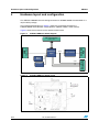
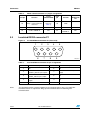
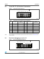
UM1077
Hardware layout and configuration
Two 3-pin jumpers with two possible positions are present on the STEVAL-IHM033V1 board,
the possible settings for which are presented in Table 1.
2.1
Power supply
The STEVAL-IHM033V1 board is designed to be powered via J1 or J4 (MC connector). See
Section 3.1.
2.2
Boot option
The STEVAL-IHM board allows boot only from embedded user Flash.
2.3
Clock source
The STM32F100CB microcontroller present on the STEVAL-IHM033V1 board is intended to
be used in conjunction with an external high speed clock (HSE) 8 MHz crystal, X1 reference
in the schematic.
2.4
Reset source
The reset signal of the STEVAL-IHM033ve board is active low and the reset sources
include:
2.5
●
Reset button B1
●
Debugging tools from connector J2
Insulated RS232
One type-D 9-pin connector, P1 (USART1), is available on the STEVAL-IHM033V1 board.
The USART1 connector is connected to the RS232 transceiver U3. The RS232 transceiver
U3 is connected to the microcontroller via optocouplers U4 and U5 which perform the
electrical insulation of the board.
2.6
16-pin SPI/I2C/SCI interface
Using this interface, it is possible to connect a device which can communicate using I2C,
SPI, and UART.
For instance, the STEVAL-PCC009V4 is an STM32 based universal USB to serial
communication interface (UUSCI). In the UUSCI demonstration board, the STM32
microcontroller is used as the interface between the PC and the end device.
Doc ID 018759 Rev 2
7/24