1
Wonderware Fanless 10.4 & 12.1” TPC & OIC Touch Panel Computers User Manual
3. INSTALLATION
Attention!
The weight of the range of the Panel PC family is approximately 7 to 14 Kg (15.5 to 31 lbs.).
Use 2 hands to carry it at all times.
3.1 PANEL PC INSTALLATION NOTES
•
•
•
•
•
•
•
The Panel PC is developed to work in a control cabinet. Therefore it must be pointed that the
environmental conditions must be considered.
When installing the Panel PC, take care that there is enough area for ventilations on rear side.
For details on the Panel PC size, go to item housing dimensions.
If you need to boot from other devices, look up for further settings for the BIOS on the single
board manuals provided in the accessory kit.
For the enclosure cutout’s, a template was included in the box the Panel PC came in. If needed,
it can also be downloaded from the Wonderware Tech Support website. Contact Wonderware
Tech Support for more information if needed.
The nuts needed to mount the Panel PC into the enclosure, are already available on the bezel
mounting studs. You need to remove these nuts prior to installing into the enclosure, for a proper
installation.
The use of Panel PC Stiffeners is required if the enclosure housing material is less then 2.5mm
(.098 or 1/10 of an inch). If there were no stiffeners in the box the Panel PC came in then please
contact your Wonderware Sales person or Distributor to obtain the following part number for your
specific Panel PC.
10.4” Panel PC Stiffener part number
99-0044
12.1” Panel PC Stiffener part number
99-0045
15” Panel PC Stiffener part number
99-0046
17” Panel PC Stiffener part number
99-0047
Install any additional PC cards into the Panel PC prior to installation into the enclosure.
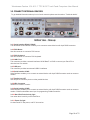
3.1.1 SEPARATION OF DISPLAY BEZEL AND PC BOX
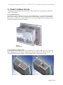
In order to aid in the installation of the Panel PC, the Display Bezel and the PC Box can be separated.
This is done by loosening 2 screws, carefully pulling the 2 pieces away from each other, and
disconnecting the 3 cables that are connected to the back of the Display Bezel. Make sure to not pull
the connections apart by the cable, but to grasp the connector its self, and gently wiggle them apart.
When reassembling them, you’ll find that there is only one connector that will fit in a particular receptacle
on the back of the Display Bezel. This way, you will not inadvertently connect to the wrong receptacle.
In the image below,
that need to be
red circle. You will
your panel will rest,
highlighted with yellow
connections are
circle.
you can see the 2 screws
loosened, highlighted with a
see 2 hinge points, where
and swing down from,
circles. Also, the data cable
highlighted with a green
Page 9 of 23