1
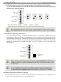
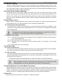
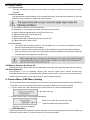
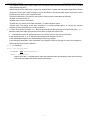
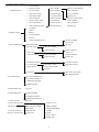
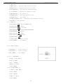
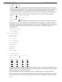
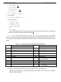
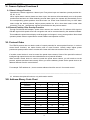
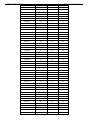
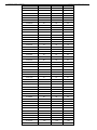
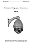
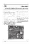
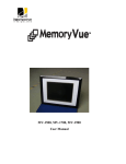
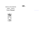
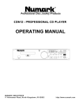
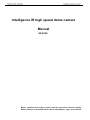
Intelligence IR high speed dome camera Manual SF-900C Before operating this product, please read this instruction manual carefully. Default setting: Protocol(PELCO-D), Baud rate(2400bps), Input power:DC12V Notes on Safety ◎Please read the instructions & quick setting guide thoroughly before installing or operating the unit. ◎Please do not mount the machine on an unstable surface or bracket. ◎Please prevent all liquids or other material from entering the dome housing. ◎When connecting the power source, please follow all electric safety standards and only use the power supply designated for this device. The speed dome’s RS-485 and video signal uses TVS technology to protect it from strong electrical surges. This technology prevents damage to the device resulting from impulse signals such as lightning strikes or surges of power. Allow for enough distance between the RS-485 and video signals and high-voltage equipment or cables during the transmission process. Please do not power the unit until all connections are secure and installation is complete. ◎Avoid shooting very bright objects directly into the camera’s CCD (such as the sun or light fittings). ◎When the machine is not operating properly, please refer to the instructions for information about how to service or repair your speed dome. ◎Please protect the unit against extremes of vibration, pressure or dampness while transporting unit. Damage can occur from improperly packaging the unit while shipping. ◎The outdoor dome camera system is designed to be installed in outdoor environments only. 1 INDEX Ⅰ. INTRODUCTION......................................................................................................................... 3 Ⅱ. TECHNICAL DATA ...................................................................................................................... 3 III. SETTINGS ................................................................................................................................... 4 3.1 DOME ADDRESS, TRANSMISSION SPEED, PROTOCOL SETTING ....................................................... 4 3.1.1 SPEED DOME CAMERA COMMUNICATION ADDRESS SETTING ................................................... 4 3.1.2 SPEED DOME CAMERA COMMUNICATION PROTOCOL SETTING ................................................. 4 3.1.3 SPEED DOME CAMERA TRANSMISSION SPEED SETTING (BAUD RATE SETTING) ........................ 5 3.2 RS-485 BUS MATCHING RESISTANCE .......................................................................................... 5 IV. BASIC FUNCTION OF DOME CAMERA .................................................................................... 5 4.1 OBJECTIVE TRACKING................................................................................................................. 6 4.2 PRESET POSITION SETTING / ADJUSTING * ................................................................................... 6 4.3 DOME PATTERN TOURS * ............................................................................................................ 6 4.3.1 Preset Position Parameter Setting..................................................................................... 6 4.3.2 Pattern Tours Setting ......................................................................................................... 6 4.4 AUTO SCANNING ........................................................................................................................ 6 4.4.1 Point A to B Scanning ........................................................................................................ 6 4.4.2 360°Scanning * ................................................................................................................. 6 4.5 OPERATING SPEED / FOCUS AUTO MATCH TECHNOLOGY ............................................................... 6 4.6 AUTO-FLIP ................................................................................................................................. 6 4.7 CAMERA CONTROL ..................................................................................................................... 7 4.7.1 Zoom Control ..................................................................................................................... 7 4.7.2 Focus Control .................................................................................................................... 7 4.7.3 Iris Control ......................................................................................................................... 7 4.8 MEMORY FUNCTION AS POWER OFF ............................................................................................ 7 4.9 AUTO-REPOSITION ...................................................................................................................... 7 V. CAMERA MENU (OSD MENU) SETTING .................................................................................... 7 VI. CAMERA OPTIONAL FUNCTIONS # ....................................................................................... 14 6.1 ALARM LINKAGE FUNCTION # ..................................................................................................... 14 6.2 PRESENT POSITION CHAR OVERLAP FUNCTION .......................................................................... 14 VII. PROTOCOL ORDER ............................................................................................................... 14 VIII. ADDRESS-BINARY CODE CHART ........................................................................................ 14 X. EXCEPTION HANDLING ........................................................................................................... 20 ---------------------------------------------------------------------------------------------------------------------------------------* indicates the functions with default protocol, it might not function by using other protocols. 2 # indicates the optional functions, only with certain models. Ⅰ. Introduction Congratulations on purchasing our speed dome, an intelligent, IR high-speed dome with a high-performance DSP camera and sophisticated zoom lens. It is an advanced technological surveillance product combining an all-direction variable speed dome and digital decoder all in one unit. It can aim quickly and scan continuously, making omni-directional and non-blind-spot monitoring into reality. Additionally, it can quickly adapt to changing environments with its 18x optical and 12x digital zoom with precise stepping motors. The advanced stepping motor technologies enable the dome to rotate smoothly, respond sensitively and aim precisely. The IR speed dome camera has a memory function so when the power cuts off it can auto resume to previous working status. Use our high-performance speed dome “When it Counts.” All of the features make the intelligent IR high-speed dome camera fit for a wide range of applications such as intelligent building, bank, street of city, airport, station etc.. Ⅱ. Technical Data Technical Parameters of the Intelligent IR High-speed Dome Outdoor Day/Night Speed Dome Model Power Supply DC12V±0.5V Operating temperature - 40℃~+60℃ Operating moisture ≤95% Power consumption ≤20W IR shoot control Indoor Speed Dome 0℃~+40℃ Low than 0.7 Lux auto on Communication RS-485 bus Protocol PELCO-D/PELCO-P Communication transmission speed 1200bps / 2400bps / 4800bps / 9600bps Horizontal rotation speed 0.1°- 180°/s (1-64 grade shift gears) Horizontal rotation range 360° Tilt rotation range 90° Auto flip 2 grades (Horizontal 180°for 1 grade, Vertical 90°for 2 Auto zoom speed control Control speed auto-adjusted according to zoom length changing A-B points scan * Can set freely A-B points scan speed * 1- 64 grade available Dwell time at preset position * 1 - 60s available Preset Positions * 128 pcs Running to preset speed * 1 - 64 grade available Cruise Tour * 8 group Cruise Points Qty per cruise group * 16 preset positions SAFER AUTOMATIC RECOGNITION st nd grade) English OSD OSD(On Screen Display Privacy zone 2(function selectable) 88 sec Cruise memery route(PATTERN) Fan & Heater # DH-SD1 Temperature auto-controlled ---------------------------------------------------------------------------------------------------------------------------------------* indicates the functions with default protocol, it might not function by using other protocols. # indicates the optional functions, only with certain models. 3 III. Settings 3.1 Dome Address, Transmission Speed, Protocol Setting Before the dome is installed, the communication protocol, baud rate and dome address, should be confirmed. Set the code switch, keeping the setting consistent with the control system. The relative code switch site and connecting wires are diagramed below for reference. SW3 NO ID SW3 NO Dome address set 1 1 2 3 2 3 4 5 6 7 3 4 5 6 7 8 4 NO Far/Near light Set FUN SW2 One machine protocol set 1 2 8 N/P Baud rate Protocol 3.1.1 IR Speed Dome Camera Communication Address Setting The communication address code for the speed dome should be properly set before use to ensure accurate addressing of the dome at the control center and to control several dome cameras. The address code is made up of SW3 (8 bits) on PCB board. The 8 bit switch uses the 8421 binary coded decimal system. The largest value is 256. 1 means ON status and 0 means OFF status. 3.1.2 IR Speed Dome Camera Communication Protocol Setting The 1st, 2nd and 3rd bits in SW2 are used to set communication protocol (see following figure) 1 Protocol PELCO-D PELCO-P DH-SD1 SAFER Protocol Protocol Protocol Protocol NO NO 2 3 4 Baud Rate 5 N/P 6 7 8 4 NO NO NO 3.1.3 IR Speed Dome Camera Transmission Speed Setting (Baud Rate Setting) The 4th and 5th bits of SW2 on the PCB board are used to set the baud rate (see following figure). The default baud rate setting is 9600 bps. Baud Rate Options: 1200bps 、2400bps 、4800bps、9600bps Please refer to the controlling device and protocol for baud rate requirement. 3.2 RS-485 Bus Matching Resistance For better centralized control, a matching resistance should be connected in a parallel way at the connecting port where the RS-485 is connected into the device which is the furthest away from the center controller. By doing this, reflection and interference from the RS-485 signal and the like can be cleared up. There is a switcher for controlling of the matching resistance in SW2. And the matching resistance is connected to the RS-485 cable when the “No. 7” switcher is set to “ON” status (see following figure). ON Software set add ON Match ON IV. Basic Function of Dome Camera Use the keyboard controller to utilize the complete potential of the speed dome. (The keyboard control protocol is set as the default protocol for the speed dome.) 5 4.1 Objective Tracking A user can rotate the camera lens up, down, left and right to view objects through the field of vision using the control keyboard. In addition, a user can adjust focal length to change the angle of view or the size of the objects. When in auto-iris and auto-zoom mode, the camera adjusts automatically to get a clear picture with changing image environments. 4.2 Preset Position Setting / Adjusting * The Preset function is the dome’s default level angle, lean angle and camera focal length in EMS memory. By using this saved parameter, the dome and camera can run to the preset positions when it is required. The operator can set and adjust preset positions by using the control keyboard; the speed dome can support 128 preset positions. (Note: It might not support 128 preset positions by using other protocols.) 4.3 Dome Pattern Tours * Before using the control keyboard to setup a speed dome pattern tour, please set the parameters of preset positions first. If not, the speed dome will run according to default setup. 4.3.1 Preset Position Parameter Setting The speed dome camera has the capacity to set preset positions through the keyboard. It can program the running speed to each preset position from 0.1º/s to 280º/s (1-64 grades) and dwell time from (1-60seconds). 4.3.2 Pattern Tours Setting 4.3.2.1. The Speed dome camera has the capacity to set up to 8 pattern tours each of which can have up to 16 preset positions. 4.3.2.2. Add preset positions in the pattern tours. 4.3.2.3. Set dwell time (1-60 seconds) and the rotational speed (1-64 grades) of each preset positions. 4.3.2.4. Start pattern tours: Cruise scanning 4.4 Auto Scanning 4.4.1 Point A to B Scanning The camera can also run a simple auto point A to B scan. By using the speed dome control keyboard, you can set the parameter of location and running speed at points A and B. 4.4.2 360°Scanning * The camera can also start an auto cruise scan. This scan will rotate 360°from the desired position. By using the speed dome control keyboard, you can set the running speed. (We suggest you do not use this function for too long time.) * indicates the functions with default protocol, it might not function by using other protocols. 4.5 Operating Speed / Focus Auto Match Technology When adjusting manually, and in the case of having a very long focus, the speed dome’s rapid reaction enables a slight touch of the joystick to result in a large movement of screen, and cause the loss of picture. Our speed dome camera automatically adjusts the rotation and tilting speed according to the distance of the focus, enabling manual objective tracking to be more simple and effective. 4.6 Auto-Flip When the speed dome camera is at vertical 90°, it flips automatically. 6 4.7 Camera Control 4.7.1 Zoom Control The user can adjust the advanced zoom feature to acquire a needed image through the control keyboard. 4.7.2 Focus Control The speed dome’s default setting is for auto-adjust focusing. Under special conditions, a user can adjust the focus manually to acquire the required image. a. The object is not in the center of the picture; b. Attempting to view images that are far and near at the same time; c. Object is strongly lighted object, such as neon lamp, etc.; d. Objects behind glass covered with dust; e. Objects moving quickly; f. Objects within large area and single color such as wall; g. Objects that are too dark or faint. 4.7.3 Iris Control The speed dome’s default setting is for auto-adjust iris. It can make an adjustment quickly through auto detecting the beam change. User can adjust iris size manually through control keyboard to get required image brightness. User can renew auto iris after moving the joystick or sending additional commands through the controller (Attn: We suggest you use auto iris). 4.8 Memory Function As Power off While power off, the speed dome will automatically save the previous operating status into it’s memory. 4.9 Auto-reposition Auto-reposition is for an important viewing point that the speed dome camera should focus automatically when there is no operation after a defined period of time. User can set the auto-reposition location also the duration time (1-60 seconds) to start or stop this function. V. Camera Menu (OSD Menu) Setting By using speed dome control keyboard, you can enter into the speed dome camera menu (OSD Menu) for setting. The menu functions will be various according to different zoom camera models. 5.1.1. Enter camera menu with Default protocol, Press FUN once, control keyboard displays: Press Enter key 5.1.2.Press FUN four times, control keyboard displays: Press CLR to clear the old data, then enter the dome address and press ENTER. The key functions are as bellow: 5.2.1 OSD Operation OSD menu provides a friendly man-machine interface. User can simply operate the dome and obtain any information from the dome, no need of memory of so many commands. 7 The method of opening the menu: OSD menu will appear on the screen for the first time of set or setting of 95 preset at any time. After entering into the OSD menu, joystick up、joystick down、joystick left and joystick right will be used to operate the menu item. When exiting the menu and back to the normal work mode, the function of the joystick will turn back to their original function. As long as OSD menu is turned on, the function of the joystick is described as following. Joystick up: Cursor move up Joystick down: Cursor move down Joystick left: The values of the item decrease 1, or select another option. Joystick right: The values of the item increases 1, or select another option, or confirm the function selected, just like a ENTER key of a PC keyboard. 5.2.2 Menu that shows the state. ">>", Show that press Enter after entering the lower-level menu. "<<" Said the press Enter after the sub-menu from which to enter the higher menu. ↑ → and that the cursor, all operations are on the current cursor to the column effectively. In the following notes, X, or on behalf of the show amend the figure of 0 to 9. In the following description, the underlined part of that can change. In the following description, italic characters in the shadow of that in the light of current circumstances, show that the content is also different. 5.2.3 OSD described。 5.2.3.1 First entering menu: 1.PASSWORD: 0000 2.EXIT << Entering Password Exit OSD menu need to enter the 4 - digit password, when the password when automatically enter the main menu. OSD menu throughout the frame structure as follows 8 1.CAMERA SETUP 2.PRESET POINT 1. FOCUS MODE 2. DIGITAL ZOOM 1.SETUP MASK 1 1.BUILD A NEW MASK 1 3. COLOR OR B/W 2.SETUP MASK 2 2.SET H WIDTH 4. WHITE BALANCE 3.CAMERA RESET 3.SET V HEIGHT 5. IMAGE REVERSE 4.AUTO EXP MODE 4.MODE OFF 6. IMAGE FREEZE 5.BRIGHT ADJUST 1.BUILD A AEW MASK 1 7. BACK LIGHT COMP 6.GAIN ADJUST 2.SET H WIDTH 8. SHUTTER SPEED 7.R GAIN ADJUST 3.SET V HEIGHT 9. NEXT PAGE SETTING 8.B GAIN ADJUST 4.MODE OFF 1. NUMBER 2. DWELL 3. DWELL 4. OVER LAPPING 5. SAVING 6. OVER LAPPING SETUP>> 1.GROUP NUMBER 2.ADD POINT 3.QUTO OPERATION 1.PRESET CRUISE 2.CRUISE TESE 3.SAUING 1.GROUP NUMBER 2.START CRUISE 3.A-B SCAN 4.A-B SCAN TEST 1.POINT A DWELL 2.SAVING A 1.A-B SCAN SPEED 3.POINT B DWELL 2.START CRUISE 4.SAVING B 5.START ROTATION 1.ROTATING SPEED 6.GUARD POINT 1.RETURING TIME 7.TURN OVER 2.OPERATION MODE 2.START ROTATION 3.SAVING 8.PATTERN 1.SET STAPT AND STOP 2.RUN THE PATTERN 4.X-Y INDICATOR 1.X LOCATOR DISPLAY 2.Y LOCATOR DISPLAY 3.TEMPERATURE DISP 4.TEMPERATURE 5.DOME SPEED OPT: 1/2/3/4/5/6 6.PASSWORD SETUP 1.NEW PSSWORD 2.CONFIRM UPDATE 3.PASSWORD PROTECT 7.LANGUAGEOPT: ENGLISH 8.SYSTEM INFORMATION 1.PROTOCOL-D/P 9.IR SETUP 1.DAY NTGHT MODE 2.BAUD RATE: 2.IR STATE 3.SPEED MODE ID COPYRIGHT RESEVED 3.OPEN IR LX 4.CODE BESTECH CORPORATION 4.DOME RESET 5.SAVE 6EXIT SUBMENU 7.VERSI出N3.2 . 9 5.2.3.2 Main OSD 1.CAMERA SETUP >> Entering camera function setting; 2.PRESET POINT >> Entering preset point setting; 3.AUTO OPERATION >> 4.X-Y INDICATOR >> Entering auto operation setting; Entering X-Y indicator setting; 5.DOME SPEED OPT >> Not support;* 6.PASSWORD SETUP >> Entering password setting; 7.LANGUAGE OPT >> Not support; * 8.SYSTEM INFORMATION SET >> 9.EXIT MENU << Entering system information setting; Exit OSD menu; 5.2.3.3 CAMERA SET >> 1.ICON DISPLAY:AUTO AUTO and MANUAL mode ; 2.DIGITAL ZOOM:OFF OFF/ON; 3.COLOR OR B/W:COLOR color/B/W; 4.WHITE BALANCE:ATW AUTO/INDOOR/OUTDOOR/ATW; 5.IMAGE REVERSE:OFF OFF/ON *; 6.CMA & EXP ICR:OFF OFF/ON; 7.BACK LIGHT COMP: OFF OFF/ON; 8.SHUTTER SPEED:AOTU 9.PRIVACY MASK >> privacy setting; 10.EXIT SUBMENU << exit submenu; 5.2.3.4 PRIVACY MASK >> 1.SETUP MASK 1 >> privacy setting 1; 2.SETUP MASK 2 >> privacy setting 2; 3.EXIT SUBMENU << exit submenu; 5.2.3.4.1 SETUP MASK 1 >> 1.BUILD A NEW 2.SET H WIDTH 3.SET V HEIGHT 4.MODE:ON MASK 1 OFF/ON 5.EXIT SUBMENU 5.2.3.4.2 SETUP MASK 2 >> 1. BUILD A NEW 2.SET H WIDTH 3.SET V HEIGHT 4.MODE:ON MASK 2 OFF/ON 5.EXIT SUBMENU 10 5.2.3.5 PRESET POINT >> 1.NUMBER: XXX (USED) Pre-selected number of points (001 to 128 optional), if the preset point has been set, the show (USED), high-speed ball at the same time will be automatically moved to the preset, user-friendly to confirm the preset points. 2, 3 and 4 are shown in the pre-point information, including the movement to the point of the preset speed, preset points in the residence time, and whether the pre-show at the characters of information. If the pre-use point yet, the show (NOT USED); 2.SPEED: XX 3.DWELL: XX (1--60) dwell time; (1--64) 4.OVER LAPPING: OFF speed value; OFF/ON; 5.SAVING· · · · All the changes only after the selection of an effective and keep the ball in the high-speed in-house, even after power, this information will not disappear. Note that in the past click Save, it is necessary to use the keyboard on the rocker (to be released first rocker, according to the IRIS CLOSE) cameras will be moved to the right location, and ZOOM to adjust to the appropriate size; 6.OVER LAPPING SETUP>> 7.EXIT SUBMENU << 5.2.3.6 AUTO OPERATION >> 1.PRESET CRUISE >> 2.CRUISE TEST >> 3.A——B SCAN >> 4.A——B SCAN TEST >> 5.START ROTATION >> 6.GUARD POINT >> 7.TURN OVER >> 8.PATTERN >> 9.EXIT SUBMENU << 5.2.3.7 PRESET CRUISE >> 1. GROUP 2.ADD NUMBER: X X is 1~8。 POINT: (01)XXX (02)XXX (03)XXX (04)XXX (05)XXX (06)XXX (07)XXX (08)XXX (09)XXX (10)XXX (11)XXX (12)XXX (13)XXX (14)XXX (15)XXX (16)XXX XXX preset point that, if empty, said the point of no pre-set point. For example: (02) 005, said the inspection teams in the second inspection point to 5 preset point. If the show: (02), said the second inspection point of no pre-set point number; The column display or modify the inspection teams, corresponding to the 16-point inspection. Users can move the cursor to the corresponding number of inspection points, binding on the preset point, be amended. If (X), it appears as a blank, said the point of no binding pre-inspection points; 3.SAVING….; 11 4.EXIT SUBMENU << 5.2.3.8 CRUIST TEST >> 1.GROUP NUMBER: X X is 1~8; 2.START CRUISE 3.EXIT SUBMENU << 5.2.3.9 A――B 1.POINT A SCAN >> DWELL: XX dwell time is 0~60; 2.SAVING…. 3.POINT B DWELL: XX 4.SAVING …. 5.EXIT SUBMENU << 5.2.3.10 A――B SCAN TEST >> SPEED: XX 1.A――B SCAN 2.STARTA――B SCAN 3.EXIT SUBMENU 5.2.3.11 << START ROTATION >> 1.ROTATION SPEED: XX 2.START ROTATION 3.EXIT SUBMENU << 5.2.3.12 GUARD POINT >> 1.RETURNING TIME: XXX 2.OPERATION MODE:ON 3.SAVING…. 4.EXIT SUBMENU << 5.2.3.13 TURN OVER >> TURN OVER:ON 5.2.3.14 PATTERN >> 1.SET START AND STOP: 2.RUN THE PATTERN: 3.EXIT SUBMENU << 5.2.3.15 X——Y INDICTOR >> 1. X LOCATOR DISPLAY:ON 2. Y LOCATOR DISPLAY:ON 3.TEMPTURE DISP:Not support※ 4. TEMPTURE:XXX Not support※ 5. EXIT SUBMENU << 5.2.3.15 DETE&TIME SETUP >> Not support. 12 5.2.3.19 PASSWORD SETUP >> 1.NEW PASSWORD: XXXX 2.CONFIRM UPDATE 3.PASSWORD PROTECT :OFF 4.EXIT SUBMENU << 5.2.3.20 LANGUAGE OPT :ENGLISH Not support. 5.2..3.21 SYSTEM INFORMATION SET >> ※ SYSTEM INFORMATION: 1.PROTOCOL: PELCO 2. BAUD RATE:9600BPS 3. SPEED DOME ID:0001 4..CODE:XXXXXX>000000 5.SAVE 6.EXIT SUBMENU<< Note: new address must be modified in 0001-0150 within the framework of choice, or beyond the scope of this system, the default address for 0150。※ 5.2.3.22. If users use PELCO protocol has no relative order in control protocol because of part special function. In order to control some special function of dome, we make function shift to usual function. Usually adopt "adjust preset position/set preset position order" to make shift. Order shift chart see as below: number Chart 1 Camera Functions by Adjusting Preset Position Keyboard Operations number Keyboard Operations Set preset position Call preset position 33 Run 180 degree 90 Set start pattern 90 Start pattern 91 Stop set pattern 91 Cursor (Up) 92 Set start location of line scan 92 Cursor(down) 93 94 95 Set end location of line scan Delete All Into Menu 93 94 95 96 97 98 99 Set Guard Position Guard position open Guard position close Day/Night Mode Switch 96 97 98 99 Cursor(left) Cursor(right) Start auto-cruise (1 preset position) Stop all funtion Start random scan Start 360 degree scan Start line scan (mid- speed) a. The menu functions will be various according to different zoom camera models. (Please read the attachment “Camera Parameter & OSD Menu” for the exact menu setting of different camera models.) 13 VI. Camera Optional Functions # 6.1 Alarm Linkage Function Speed dome camera supports a 4 alarm input. Every alarm input end matches a preset position No.: 29, 30, 31, 32. When speed dome camera detects an alarm input, the camera will automatically turn to the preset position that has been set. When detecting several alarm inputs, the camera will automatically turn to the corresponding preset positions that have been set. Press down Shift+CLR key to clear alarm status under the default protocol. Adjust preset position No. 60 to clear alarm status under other protocols. Then the speed dome camera will come back to the previous status. 6.2 Present Position Char Overlap Function Through RS-232/RS-485 adapter, speed dome camera can transfer the PC deferent 232 signal to RS-485 signal which speed dome can recognize and can be communicated by the attached software. This enables the speed dome display multi-language and images in every preset position. More detail operation please refers to speed dome control software and operation manual. VII. Protocol Order The PELCO protocol has no relative order of control protocols for some special functions. In order to control these functions, we make function shift to usual function. Usually adopt "adjust preset position/set preset position order" to make shift. Order shift chart see as above chart 1 and 2. If another control device is used to control the speed dome camera, Some of the special functions of Intelligent high speed dome can’t be realized because of protocol limitation. When another control device is used to control the speed dome camera, you will need to set the protocol, address and baud rate correctly. When you set the address, please set the speed dome to an address different from the control device. For example: DVR address is 1, dome camera address should be set as 2 for normal control. ---------------------------------------------------------------------------------------------------------------------------------------# indicates the optional functions, only with certain models. VIII. Address-Binary Code Chart Binary System Code Default Protocol PELCO-D PELCO-P 00000000 1 1 1 00000001 2 2 2 00000010 3 3 3 00000011 4 4 4 00000100 5 5 5 00000101 6 6 6 00000110 7 7 7 00000111 8 8 8 00001000 9 9 9 00001001 10 10 10 00001010 11 11 11 00001011 12 12 12 00001100 13 13 13 14 00001101 14 14 14 00001110 15 15 15 00001111 16 16 16 00010000 17 17 17 00010001 18 18 18 00010010 19 19 19 00010011 20 20 20 00010100 21 21 21 00010101 22 22 22 00010110 23 23 23 00010111 24 24 24 00011000 25 25 25 00011001 26 26 26 00011010 27 27 27 00011011 28 28 28 00011100 29 29 29 00011101 30 30 30 00011110 31 31 31 00011111 32 32 32 00100000 33 33 33 00100001 34 34 34 00100010 35 35 35 00100011 36 36 36 00100100 37 37 37 00100101 38 38 38 00100110 39 39 39 00100111 40 40 40 00101000 41 41 41 00101001 42 42 42 00101010 43 43 43 00101011 44 44 44 00101100 45 45 45 00101101 46 46 46 Binary System Code Default Protocol PELCO-D PELCO-P 00101110 47 47 47 00101111 48 48 48 00110000 49 49 49 00110001 50 50 50 00110010 51 51 51 00110011 52 52 52 00110100 53 53 53 00110101 54 54 54 00110110 55 55 55 00110111 56 56 56 00111000 57 57 57 00111001 58 58 58 00111010 59 59 59 00111011 60 60 60 00111100 61 61 61 15 00111101 62 62 62 00111110 63 63 63 00111111 64 64 64 01000000 65 65 65 01000001 66 66 66 01000010 67 67 67 01000011 68 68 68 01000100 69 69 69 01000101 70 70 70 01000110 71 71 71 01000111 72 72 72 01001000 73 73 73 01001001 74 74 74 01001010 75 75 75 01001011 76 76 76 01001100 77 77 77 01001101 78 78 78 01001110 79 79 79 01001111 80 80 80 01010000 81 81 81 01010001 82 82 82 01010010 83 83 83 01010011 84 84 84 01010100 85 85 85 01010101 86 86 86 01010110 87 87 87 01010111 88 88 88 01011000 89 89 89 01011001 90 90 90 01011010 91 91 91 01011011 92 92 92 01011100 93 93 93 Binary System Code Default Protocol PELCO-D PELCO-P 01011101 94 94 94 01011110 95 95 95 01011111 96 96 96 01100000 97 97 97 01100001 98 98 98 01100010 99 99 99 01100011 100 100 100 01100100 101 101 101 01100101 102 102 102 01100110 103 103 103 01100111 104 104 104 01101000 105 105 105 01101001 106 106 106 01101010 107 107 107 01101011 108 108 108 01101100 109 109 109 16 01101101 110 110 110 01101110 111 111 111 01101111 112 112 112 01110000 113 113 113 01110001 114 114 114 01110010 115 115 115 01110011 116 116 116 01110100 117 117 117 01110101 118 118 118 01110110 119 119 119 01110111 120 120 120 01111000 121 121 121 01111001 122 122 122 01111010 123 123 123 01111011 124 124 124 01111100 125 125 125 01111101 126 126 126 01111110 127 127 127 01111111 128 128 128 10000000 129 129 10000001 130 130 10000010 131 131 10000011 132 132 10000100 133 133 10000101 134 134 10000110 135 135 10000111 136 136 10001000 137 137 10001001 138 138 10001010 139 139 10001011 140 140 10001100 141 141 Binary System Code Default Protocol 10001101 142 142 10001110 143 143 10001111 144 144 10010000 145 145 10010001 146 146 10010010 147 147 10010011 148 148 10010100 149 149 10010101 150 150 10010110 151 151 10010111 152 152 10011000 153 153 10011001 154 154 10011010 155 155 10011011 156 156 10011100 157 157 17 PELCO-D PELCO-P 10011101 158 158 10011110 159 159 10011111 160 160 10100000 161 161 10100001 162 162 10100010 163 163 10100011 164 164 10100100 165 165 10100101 166 166 10100110 167 167 10100111 168 168 10101000 169 169 10101001 170 170 10101010 171 171 10101011 172 172 10101100 173 173 10101101 174 174 10101110 175 175 10101111 176 176 10110000 177 177 10110001 178 178 10110010 179 179 10110011 180 180 10110100 181 181 10110101 182 182 10110110 183 183 10110111 184 184 10111000 185 185 10111001 186 186 10111010 187 187 10111011 188 188 10111100 189 189 Binary System Code Default Protocol 10111101 190 190 10111110 191 191 10111111 192 192 11000000 193 193 11000001 194 194 11000010 195 195 11000011 196 196 11000100 197 197 11000101 198 198 11000110 199 199 PELCO-D PELCO-P 11000111 200 200 11001000 201 201 11001001 202 202 11001010 203 203 11001011 204 204 11001100 205 205 18 11001101 206 206 11001110 207 207 11001111 208 208 11010000 209 209 11010001 210 210 11010010 211 211 11010011 212 212 11010100 213 213 11010101 214 214 11010110 215 215 11010111 216 216 11011000 217 217 11011001 218 218 11011010 219 219 11011011 220 220 11011100 221 221 11011101 222 222 11011110 223 223 11011111 224 224 11100000 225 225 11100001 226 226 11100010 227 227 11100011 228 228 11100100 229 229 11100101 230 230 11100110 231 231 11100111 232 232 11101000 233 233 11101001 234 234 11101010 235 235 11101011 236 236 11101100 237 237 Binary System Code Default Protocol 11101101 238 238 11101110 239 239 11101111 240 240 11110000 241 241 11110001 242 242 11110010 243 243 11110011 244 244 11110100 245 245 11110101 246 246 11110110 247 247 PELCO-D PELCO-P 11110111 248 248 11111000 249 249 11111001 250 250 11111010 251 251 11111011 252 252 11111100 253 253 19 11111101 254 254 11111110 255 255 11111111 256 256 X. Exception Handling Issue Possible Reason Solution Power on, no movement, no image, indicator light does not light Power line connected wrong Correct it Power damaged Replace Blowout Replace Power line be connected bad Check it Power on, self check, has image, can’t control, indicator light does not flicker The machine’s address code or baud rate is wrong Reset Protocol wrong Correct it RS485 bus be connected wrong Check it Camera can’t reposition itself. (camera can no longer move) Mechanical failure Repair it Camera incline Correct it Power is not enough Replace Image is not stable Video line connected bad Check it Power is not enough Replace Focus in manual state Operate the machine or adjust a preset position Dome is dirty Clean it Power supply is not enough Change a certified power supply The matching resistance of the furthest speed dome is not working Makes the matching resistance work Camera can not control resulting from incorrect operation Reboot the machine Image is dim Control is not stable 20