1
Chapter 2
Preparation and Inspection
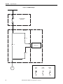
Lockout and tagout the input circuit breaker before opening the doors to the
drive system cabinets. After the cabinet doors are opened, immediately test the
incoming and outgoing power cables and any components connected to medium
voltage with a live-line tool (hot stick) while wearing high voltage gloves. Pay
special attention to any capacitors connected to medium voltage that can retain a
charge for a period of time. Only after the equipment has been verified as isolated
and de-energized can subsequent work be performed. Even though the input to
the drive may be open, it is still possible for hazardous voltage to be present.
Refer to local safety guidelines for detailed procedures on how to safely isolate
the equipment from hazards.
Safety Test
Complete every point included in this section prior to continuing with the drive
commissioning, to ensure that the commissioning continues in an environment
safe to all those involved in servicing the drive. Ensure that commissioning of this
drive is performed in accordance with local safety standards.
Inspect Drive Components
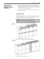
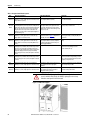
After performing the lockout and tagout procedure (see page 15), open all of the
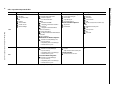
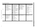
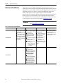
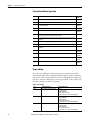
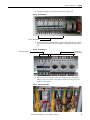
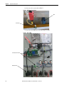
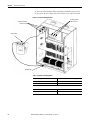
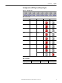
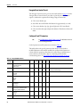
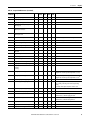
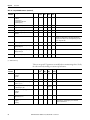
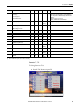
cabinet doors. Inspect each component for signs of shipping damage (see Table 3
on page 18). An initial inspection would have been done by the customer when
the equipment was received. However, this would have been done from the front
only and was just looking for obvious signs of damage (see publication 6000IN006_-EN-P). Record the part number and description of any damaged
components and immediately contact the Start-up Project Manager to order
replacement components, if required.
ATTENTION: Verify the equipment against any damage. Do not install a
damaged drive.
Verify that all components are securely affixed to the cabinet.
Most components will be easily visible on the doors or from the front of the
cabinets after the doors are opened. Some components are best viewed from the
rear of the cabinet.
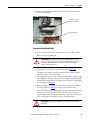
For rear inspection, remove top and bottom rear access plates from the drive and
bypass cabinet (if supplied). See publication 6000-IN006_-EN-P.
IMPORTANT
16
The Inspect Drive Components Checklist (see page 18) mentions the principal
base components supplied in the drive and bypass units. It is not
comprehensive, as customer-required options may be supplied and three
different bypass configurations are available.
Perform the shipping damage inspection for all components mounted in the
drive cabinets and specific bypass unit cabinet (if supplied).
Rockwell Automation Publication 6000-IN007A-EN-P - October 2014