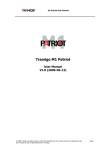
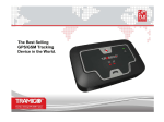
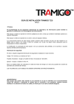
1
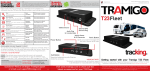
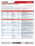
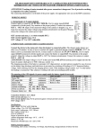
Immobilizer Guide
Tramigo™ T23 Fleet
Immobilizer Guide
V.1.07.4
1
© 2007 - 2013 Tramigo™ Ltd. All rights reserved. Under the copyright laws, this manual cannot be reproduced in any form
without the prior written permission of Tramigo™.
Immobilizer Guide
This installation guidance is for the Tramigo™ T23 Fleet IMMOBILIZER12 and IMMOBILIZER24.
The Immobilizer feature is used to disable a car’s ignition. This option requires special wiring that
must be done carefully to ensure trouble-free operation. With this feature active a car will not start
even if the T23 Fleet is removed.
IMPORTANT NOTICE:
This is an explanatory installation scheme only. Variation may be required depending to the type of vehicle or
machine to which T23 Fleet will be installed. All possible direct and indirect damages caused by the
installation are the sole responsibility of the installer or installing body. The installer or installing body is
responsible to test and ensure the functionality of their installation. All possible direct and indirect damages
caused by the use of the immobilizer are the sole responsibility of the end user. Tramigo™ Ltd’s manufacturer
responsibility is limited to the function of Tramigo T23 Fleet unit as stated in the warranty clause that can be
found from the User Manual and is not extended in any way for the installation done by a third party.
The installation should always be done only by professional auto-electrician, which have been properly
trained to install or service the Immobilizer. We recommend that you do NOT install the Immobilizer yourself,
unless you are a professional auto electrician and knowledgeable about the Immobilizer.
The installer or installing body is responsible that the installation complies with local legislation. Additionally
if the Immobilizer is to be installed to a vehicle the installer, Installing body and the end user are responsible
to check the local legislation regarding the execution of the immobilization command and comply with the
regulations. Extreme caution must always be used if the immobilization command is executed on a moving
vehicle and the immobilizer is installed to disable the engine rather than the starter. SMS can take a while to
be received, so the vehicle may be in a dangerous location or travelling at a high speed when the immobilizer
is activated. Vehicle’s engine will be shut down, power steering will be lost and the vehicle will be difficult to
control.
The disable command is used to activate the immobilizer. Disable,on prevents the engine from
starting or stops the engine depending on the installation. This will occur immediately if the vehicle is
parked or 45 seconds after the ignition has been turned off, and vehicle is not in moving state.
Disable,off allows the engine to start. You must have SMS coverage to be able to use these
commands. Disable,on,forced shall immobilize the vehicle regardless of the vehicle state. Please use
this command with extra caution.
This feature is supported by firmware v.1.07 or higher
Command:
Disable,on
Disable,on,forced
Disable,off
- immobilizer will engage only when it meets conditions
- immobilize the vehicle as soon as T23 Fleet receives the SMS.
- immobilizer has been turned off and vehicle may function again.
Vehicle must have GSM coverage for these commands to work.
2
© 2007 - 2013 Tramigo™ Ltd. All rights reserved. Under the copyright laws, this manual cannot be reproduced in any form
without the prior written permission of Tramigo™.
Immobilizer Guide
Conditions:
Car should be stopped or parked
Not moving
Car’s speed is < 15km/h
Ignition is off
The immobilizer works as follows:
Note you have to use Ignition sensing with the immobilizer option.
What To Do?
Report/s to be Received
Scenario 1. Vehicle is parked, (speed < 15km/h), ignition is off.
Send DISABLE,ON command
Tramigo: Disable, vehicle
ignition disabled, 18:29 May 31
Effect/Result
Immobilizer takes effect
immediately. Vehicle will not be
starting up after activation.
NOTE: not in trip mode – vehicle
has been parked with ignition off
for 15 minutes
Scenario 2. Vehicle is moving.
Send DISABLE,ON command
Tramigo: Disable, Vehicle
ignition will be disabled 45
seconds after the ignition is
turned off, 18:32 May 31
Immobilizer will take effect when
ignition has been switched off for
45 seconds and the speed is below
15km/h.
Scenario 3. Vehicle is immobilized and won’t start.
Send DISABLE,OFF command
3
Tramigo: Disable, vehicle
ignition enabled, 18:39 May 31
Immobilizer will disengage. Vehicle
may be started.
© 2007 - 2013 Tramigo™ Ltd. All rights reserved. Under the copyright laws, this manual cannot be reproduced in any form
without the prior written permission of Tramigo™.
Immobilizer Guide
Installation:
Vehicle manufacturers warranty may be voided if the install is not done by their staff. Take these
instructions and parts to their service center for installation.
Requirements:
Figure 1
T23 Fleet IMMOBILIZER
1 ORANGE wire (Normally Open Switch)
7 T22-OEM Molex connector
2 Wires for OVERRIDE SWITCH or BYPASS*
8 Thin RED wire - no connection
3 YELLOW wire (Normally Closed Switch)
9 BLUE wire for Ignition Sensing
4 RED wire (with fuse) to +12/24V
10 Immobilizer FUSE
5 Thin BLACK wires to GND
11 BROWN wire for SOS / ATB
6
GREEN wire to Ignition Key
Note: It’s highly recommended to install an override switch located in a discreet place
where the owner can find it. This prevents them from getting stuck if there is a problem
with GSM coverage, T23 Fleet, wiring, or the relay. To use the owner presses the switch
while turning the ignition.
* for Normally Open Connection only
4
© 2007 - 2013 Tramigo™ Ltd. All rights reserved. Under the copyright laws, this manual cannot be reproduced in any form
without the prior written permission of Tramigo™.
Immobilizer Guide
Configuration:
Configure your T23 Fleet for Immobilizer feature with Ignition Sensing, SOS button and Power cut.
Send the following commands via SMS or Tramigo Manager to your T23 Fleet
INPUTs for ignition sensing activation:
Set,IgnitionInputGPIO,1
Set,IgnitionInputShock,0
Ignition,On - (optional) to activate ignition on/off reporting
SOS button activation (optional):
INPUT,2,SOS,SOS,0,2000,ON
Set,SOSGPIO,1
Power cut alarm activation:
Input,3,general,powercut,0,5000,on
Powercut,on
For normally open circuit (ORANGE wire in use):
Output,1,Immobilizer,Disable,0,0
For normally closed circuit (YELLOW wire in use):
Output,1,Immobilizer,Disable,1,0
Tip: If you are installing many T23 Fleet, save these messages in your phone.
For more details on NORMALLY OPEN or CLOSED CIRCUITS, please check pp. 8 – Hints and Tips
5
© 2007 - 2013 Tramigo™ Ltd. All rights reserved. Under the copyright laws, this manual cannot be reproduced in any form
without the prior written permission of Tramigo™.
Immobilizer Guide
Wiring Diagram:
Figure 2
Immobilizer Installation Wiring Diagram
NOTES:
1) Choose only ONE (1) connected wire on starter from WIRE #1 or #2.
2) Wire #1 is connected only if you have to use the “Normally Closed Circuit” of the immobilizer.
3) Wire #2 is connected only if you have to use the “Normally Open Circuit” of the immobilizer.
4) Ignition sensing (BLUE WIRE) should be connected to the node/wiring, which has power on for
the whole driving trip, not only for cranking.
6
© 2007 - 2013 Tramigo™ Ltd. All rights reserved. Under the copyright laws, this manual cannot be reproduced in any form
without the prior written permission of Tramigo™.
Immobilizer Guide
Wiring Explained:
1.
2.
3.
4.
When you cut the Ignition cable/wire into two, test one end with multitester (or even bulb), the side
that gives voltage or lights up is for the GREEN wire and the other side staying blank is for the
YELLOW or ORANGE wire, in whichever option you desired to use.
5.
7
© 2007 - 2013 Tramigo™ Ltd. All rights reserved. Under the copyright laws, this manual cannot be reproduced in any form
without the prior written permission of Tramigo™.
Immobilizer Guide
24V Installation
Older truck installations which have been measured to provide constantly more than 24V can cause
unwanted behaviour, such as, T23 unit stops charging due to damaged I/O port; or unit stops
responding; or unit hangs.
- Install Voltage Regulator power wires between the RED thick wire’s fuse
and Immobilizer power input.
- Ground wires between ground and Immobilizer thin BLACK wires.
Refer to wiring diagram below.
NOTE: In 24V systems voltage regulator is mandatory to prevent power surges to T23 unit.
If questions, contact to Tramigo support, please email [email protected]
8
© 2007 - 2013 Tramigo™ Ltd. All rights reserved. Under the copyright laws, this manual cannot be reproduced in any form
without the prior written permission of Tramigo™.
Immobilizer Guide
Hints and Tips:
Add a hidden override switch to bypass the T23 Fleet immobilizer. - This would be useful if in
case you send a disable command. Then if the vehicle goes to a place where it has no GSM
signal, sending command to enable vehicle again won’t be possible. Also useful should your
T23 Fleet be taken away which will permanently disable your vehicle. You can attach a switch /
button to the white wires if you want to implement this.
NOTE: This is for the Normally Open Circuit connection. For Normally Closed Circuit, you can
disconnect the unit.
You may want to disable sleep mode so that your unit is always online and ready. When unit is
in deep sleep mode it will not be able to process your request and may not be able to receive
your command. T23 Fleet will however wake to any movement. To disable sleep mode, send
Set,Sleep,0 to your T23 Fleet
There is T23 Fleet IMMOBILIZER12 and T23 Fleet IMMOBILIZER24 for 12V and 24V systems
respectively.
To test your connection unplug the I/O cable from the T23 Fleet, the vehicle should go
off/won’t start.
If your immobilizer is not working despite the right wirings, try reversing the GREEN and
YELLOW wires.
Three most common places for installing the immobilizer is the starter motor, ignition, or the
fuel pump. For petrol engines you can use ignition and for diesel engines starter. However, for
forced stopping of the vehicle, fuel pump is the safest but this installation must only be made
by authorized installer with fuel pump experience. For new cars not applicable of the previous
options, there can be a possibility to immobilize the vehicle computer system or use the
existing immobilizer.
Normally closed connection (YELLOW WIRE) is used in “fail-safe” installations. If
unit runs out of battery, is disconnected or any other problem, the vehicle will NOT be
immobilized.
Normally open connection (ORANGE WIRE) should be used only in starter engine
installations, and special non-tampering cases. If unit runs out of battery, is
disconnected or any other problem, the vehicle WILL BE IMMOBILIZED.
Vehicle GND refers to any metallic part of the chassis.
Use special cloth black adhesive tape which is used by car manufacturing companies, so the
wiring looks like it has not been tampered.
Should there be some unclear details, please email [email protected]
9
© 2007 - 2013 Tramigo™ Ltd. All rights reserved. Under the copyright laws, this manual cannot be reproduced in any form
without the prior written permission of Tramigo™.