1
Aquarius 5000
Pedestrian Kit Option
USER'S MANUAL
0311382 Rev A
Issue : September 1998
DSNP makes no warranty of any kind with regard to this equipment,
including, but not limited to, the implied warranties of merchantability
and fitness for a particular purpose. DSNP shall not be liable for errors
contained herein or for incidental consequential damages in connection
with the furnishing, performance, or use of this equipment
This manual contains proprietary information which is protected by
copyright. All rights are reserved. No part of this document may be
photocopied, reproduced or translated into another language without
the prior written consent of DSNP.
The information contained in this manual is subject to change without
notice.
Pedestrian Kit Option User’s Manual
Table of Contents
Table of Contents
1. Description & Requirements.............................................1-1
Description .................................................................................. 1-1
Unpacking...................................................................................... 1-1
Mounting the receiver on the metal support .................................. 1-5
Hardware and software requirements ......................................... 1-6
2. Preparing for a field survey ..............................................2-1
Assembling the various parts ...................................................... 2-1
Connections ................................................................................ 2-3
Getting ready for surveying ......................................................... 2-4
Introduction to the Rover Unit Software Interface ....................... 2-5
3. Field Surveying ..................................................................3-1
Start-up sequence ....................................................................... 3-1
Staking out target points.............................................................. 3-5
Logging points ........................................................................... 3-13
Logging trajectories ................................................................... 3-15
Offset staking-out ...................................................................... 3-20
Offset logging ............................................................................ 3-22
If the selected project
is based on an unknown local grid ............................................ 3-28
DSNP
i
Pedestrian Kit Option User’s Manual
Table of Contents
Setting the max. permitted radial and
vertical uncertainties.................................................................. 3-31
Initialisation modes and processing modes .............................. 3-32
Opening another job file for your project ................................... 3-34
Changing project ....................................................................... 3-34
Auxiliary displays ....................................................................... 3-35
ii
DSNP
Description & Requirements
Description
1. Description & Requirements
1
Description
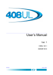
Unpacking
The Pedestrian Kit Option consists of two distinct containers:
one for the accessories, the other for all the parts required to
carry the Aquarius receiver on an operator’s back.
The accessory container is described below. DSNP reserves
the right to make changes to this supply without prior notice.
FSP70, 0 dB flexible UHF antenna
3310190 (415/435 MHz)
or 3310196 (430/450 MHz)
or 3310188 (450/470 MHz)
Accessory container
Part No. 790076562
Receiver container
Part No. 790076561
FS/GS
palmtop
computer and
internal battery
Part No.
317076375
2 NiCd
Battery packs
Part No.343088
for rover unit
DSNP
Quick release
adaptor
Part No.
26I2076528
+1 PCMCIA Card
Part No. 4660039
& User's Manual
(Not provided)
1-1
1
Description & Requirements
Description
GPS antenna:
NAP001 (L1) Part No.26E1076311 or
NAP002 (L1/L2) Part No. 26E1076208
with 5/8" adaptor Part No. 724076577
Mast for GPS antenna
Part No. 26I2076564
Bag of clips
Part No. 7870088
Mast for UHF
antenna
26I2076840
(includes UHF
coaxial cable
Part No.
505076499)
(Not provided)
FS/GS palmtop cable, pp/SubD Part No. 605076501, 1.0 m
FS/GS-PC cable, SubD9/SubD9 Part No. 605076502, 1.0 m
GPS coaxial cable (pp/TNCm) Part No. 505076500, 1.5 m
UHF coaxial cable (TNCm/TNCm) Part No. 5050227, 2.50 m
Palmtop support for
telescopic pole, Part
No. 7510423
Telescopic Pole 1337-L,
Part No. 3310203
(supplied separately)
1-2
DSNP
Description & Requirements
Description
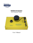
The content of the other container (the Receiver container) is
described below. This box contains the battery charger and
the rover unit assembly. The photos below show the Aquarius
receiver once it has been inserted into the holder and secured
on the metal support.
1
Note that once all the parts have been assembled, the
assembly can be directly placed in the container for
transportation (see photo on right).
Your
Shoulder straps and belt, receiver
Part No. 751076678
Receiver holder
(black) Part No.
751076466
Battery Charger
Part No. 3440005
Metal Support
Part No. 751076467
DSNP
Battery compartment
Part No. 26I2076679
Rover unit assembly
Part No.26I2076548
1-3
1
Description & Requirements
Description
The rover unit assembly (Part No. 26I2076548) consists of
the following parts:
- the stand, Part No. 26E1076942, which consists of
the receiver holder (Part No. 751076466, black
rubber), the Metal support (Part No. 751076467) and
small parts (screws, washers, standoffs).
- the battery compartment, Part No. 26I2076679
(which includes 2 battery cables Part No.
605076507)
- Shoulder straps and belt, Part No. 751076678,
including a serial line cable (605076509, 0.75 m) and
a GPS antenna cable (605076510, 0.75 m, coaxial,
50 Ω).
- Small parts (screws, washers, standoffs)
Note the two cables present in the belt at delivery. Do not
remove these cables from the belt as they are precisely
required at this location for your field surveys.
Also, they needn't be removed before putting the rover unit
assembly back into its container for transportation.
1-4
DSNP
Description & Requirements
Description
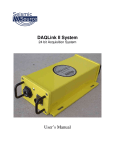
Mounting the receiver on the metal support
1. Insert your Aquarius receiver into the black holder.
2. Insert the standoffs into the 4 holes of the black
holder (on rear side)
1
3. Position the holder/receiver assembly on the metal
support
4. From behind the metal support, insert the 4 washers
and screws into the holes
5. Secure the receiver and its holder on the metal
support by tightening the 4 screws
Warning! Do not forget to insert the standoffs (step
2. above), otherwise tightening the screws (step 5)
will irreversibly damage the holder.
DSNP
1-5
1
Description & Requirements
Hardware and software requirements
Hardware and software requirements
The following hardware and software elements are required to
allow the use of the Pedestrian Kit Option:
- UHF data link option (your Aquarius receiver must be
fitted with a built-in UHF receiver for reception of
data from a base station)
- KART processing option (if the receiver engine is L1
only) or LRK processing option (if it’s L1/L2).
1-6
DSNP
Preparing for a field survey
Assembling the various parts
2. Preparing for a field survey
Assembling the various parts
1
2
4
3
2
5
After inspecting all the parts provided and after mounting the
receiver on the metal support for portable operations (see
section 1), proceed as shown above:
1. Secure the palmtop on its holder.
2. Insert the pointed end of the telescopic pole into the
hole of the palmtop support.
3. Secure the support somewhere on the telescopic
pole so that the palmtop be at a proper height (i.e.
adapted to your own height).
4. With a thumb, depress the quick release button on
the support and insert the tipped end of the palmtop
holder into the support. Release the button.
DSNP
2-1
2
Preparing for a field survey
Assembling the various parts
5.
Secure the quick release adapter in the lower part of
the GPS antenna.
6
8
7
10
9
6.
With a thumb, depress the button on the quick
release adaptor and insert the top of the pole into the
adaptor. Release the button.
7.
Give the GPS antenna the desired height by
adjusting the length of the telescopic pole.
8.
Insert fresh battery packs into the battery
compartment (a single way possible for battery
insertion).
9.
Do not forget to lock the battery compartment.
11
10. Screw the UHF antenna on top of the mast and
insert the mast into the dedicated location on the
receiver holder.
11. Make the necessary connections (described in the
next page).
2-2
DSNP
Preparing for a field survey
Connections
Connections
- Connect the end of the coaxial cable (protruding from
the belt) to the GPS antenna.
- Connect the end of the serial line cable (protruding
from the belt) to the palmtop.
- Make sure the palmtop is fitted with the NiCd battery
pack.
2
- Connect the end of the coaxial cable protruding from
the UHF antenna mast to the DGPS input (on
receiver rear panel).
GPS antenna
0 dB UHF antenna (whip)
DC power source
(from battery compartment)
connected to either POWER
connector
RS232
push-pull
connector
Telescopic
pole
Palmtop
Coaxial
push-pull
connector
Receiver Rear Panel
DSNP
2-3
2
Preparing for a field survey
Getting ready for surveying
Getting ready for surveying
- Insert the PCMCIA containing the
project into the receiver.
- Switch on the GNSS receiver by
depressing the ON/OFF pushbutton.
- Put the rover unit assembly on your
back
- Switch on the palmtop by depressing the red key (top
right).
Operator ready for field operations
2-4
DSNP
Preparing for a field survey
Introduction to the Rover Unit Software Interface
Introduction to the Rover Unit Software
Interface
- The Rover Unit Software Interface will assist you in
every step of your field works.
- From any display shown on your palmtop, you can
freely access any other display by pressing a single
key (except at power-on until you choose a project).
Said differently, all displays are arranged
"horizontally" at the same level .
Display #1
Display #2
..
.
Display #9
..
.
Display #A
2
Display #I
- For most of the displays, two viewing modes exist as
explained below.
• The
Read mode, which is the default
mode when accessing the display, just
lets you read, not change, the data on
the screen
• The
Edit mode, which you validate and
leave by pressing ↵ (the ENTER or YES
key), lets you change the modifiable
data on the screen
DSNP
2-5
2
Preparing for a field survey
Introduction to the Rover Unit Software Interface
- A few keys need to be known for best use of the
software interface program:
• Pressing the ∗ key will display the main
menu listing all the accessible displays.
Use the PgUp/PgDn keys to scroll
through the entire main menu.
• From this list, and generally from any
display in Read mode or from the
program menu only (default mode), the
keys 0 to 9, A to I, allow you to access
the corresponding displays. For
example, pressing "2" will cause display
#2 to appear on the screen.
2-6
DSNP
Preparing for a field survey
Introduction to the Rover Unit Software Interface
• After selecting the desired display, pressing the ↵ (or
Yes) key allows you to enter the Edit mode for that
display. You cannot select another display until you
quit the Edit mode by pressing ↵ again.
• In
Edit mode, after modifying parameters on the
• In
Edit mode only, the "sp" key" or the dot" key (.) are
screen, pressing ↵ will cause he program to validate
the new values assigned to these parameters.
2
used in those fields where only preset values can be
entered. In this case, pressing either of these keys
repeatedly will let you view all the possible values for
the field.
Edit mode only, the keys ← ↑ → and ↓ allow you
to move the cursor within a field and from a field to
an adjacent one.
• In
• In
Edit mode only, the Del/No key allows you to quit
this mode without validating the changes you made
on that screen.
• The Esc key allows you to quit the program.
DSNP
2-7
2
Preparing for a field survey
Introduction to the Rover Unit Software Interface
• All displays are divided into two distinct areas as
shown below. The status area is permanently shown
whatever the display chosen.
UHF datalink indicator
Current processing
Processor activity
"SV used" Bargraph
Active-Display
Parameter Area
Status Area
UHF datalink indicator:
: UHF Datalink okay
: No UHF Datalink
Current processing mode:
H : Hold (no position solution)
G : GPS
E : EDGPS (metric accuracy)
K : KART (centimetric accuracy)
L : LRK (centimetric accuracy)
"SVs used" bargraph:
: GPS reception okay
: Minimum GPS reception required
: No GPS reception
2-8
DSNP
Preparing for a field survey
Introduction to the Rover Unit Software Interface
- Alarm report:
• Message boxes will appear on the
screen together with a specific sound
(see below) in case of satellite or
battery alarm.
- The buzzer will sound in the following cases:
• At the end of the initialization phase, not
2
an alarm (beeps three times)
• Satellite alarm (brief 3-tone "down"
sound every 6 seconds approx.)
• Battery alarm (brief 3-tone "up" sound
every 6 seconds approx.)
• Invalid display request (brief 2-tone
sound)
• Invalid data entry (brief 2-tone sound)
• Other errors (brief 2-tone sound)
DSNP
2-9
2
Preparing for a field survey
Introduction to the Rover Unit Software Interface
2-10
DSNP
Field Surveying
Start-up sequence
3. Field Surveying
Start-up sequence
Assuming the rover unit is now ready and you have the
palmtop in hand, do the following:
- From the DOS prompt, type in "M" (not casesensitive) and press ↵.The following screens appear
in sequence:
3
...
...
...
DSNP
3-1
3
Field Surveying
Start-up sequence
• Choosing a project
(Continued from preceding page)
This unconditional start-up sequence leads you to choose a
project among those stored on the PCMCIA (and implicitly to
select the coordinate system required for the project).
- Use the ↑ and ↓ keys to move the cursor within the
list. The first project in the list is selected by default.
Note that each project appears twice in the list.
Choose one of the two knowing that:
just contains
- the selection preceded by
the reference points of the project.
just contains
- the selection preceded by
the target points of the project.
NOTE: In fact, when you create a project
with KISS, two files are generated: one
containing the reference points of the
project (project.ref), the other the target
points of the project (project.tar). Because
these files are expected to let the rover unit
know which coordinate system should be
used for the project, they are systematically
created by KISS, even if they do not contain
a single point.
- After choosing the item containing the target points
(typical choice), press ↵. After a few seconds, a new
display (Display #5) appears on the screen (see next
page).
3-2
DSNP
Field Surveying
Start-up sequence
• Opening a job file
(Continued from preceding page)
Default name for your job
3
Information on the project,
read from the PCMCIA
The default name prompted for your job file is in the form
“mmddhhmm” (month, day, time). Note the position of the
cursor on the leftmost figure.
- If required, change the job file name and also the
next parameters. Use the arrow keys to move the
cursor within the framed area.
DSNP
3-3
3
Field Surveying
Start-up sequence
- Press ↵. Display #5 should now look like this if you
have not made any changes to the previous screen:
Validated name for your job, file now open
Described in page 3-31
The symbol ( ) appearing to the right of the
validated file name indicates that the file is now open
and ready to receive the field data.
You have now reached the end of the unconditional
start-up sequence, which means that you can now
have free access to any of the displays available on
your palmtop.
Unless the L (or K) processing mode is now
displayed in the status area, wait for this letter to
appear before proceeding with your work. When
displayed, this letter denotes successful LRK (or
KART) initialisation and the ability for the rover unit to
start your work.
NOTE: OTF initialisation is the default initialisation
mode run by the unit.
3-4
DSNP
Field Surveying
Staking out target points
Staking out target points
Now that your rover unit is initialised, do the following:
- Press “6”. A new screen appears listing all the target
points of the selected project (display #6).
(Ignore this information)
3
- Press ↵: the cursor now appears on the target point
the closest to your current position, prompting you to
survey this point first.
NOTE: Later, in this particular context, you can
ask the system to search for the closest point —
because in the meantime another point was selected
or you moved to another location — by simply
pressing the “N” key. Somewhere within the list, the
closest point will be marked with a .
If you cannot access display #6 (“Disabled screen,
Coord. system invalid” message displayed), please
refer to page 3-28, If the selected project is based on
an unknown local grid).
DSNP
3-5
3
Field Surveying
Staking out target points
- To choose another point, move the cursor using the
↑ and ↓ keys.
(Ignore this information)
- Press ↵ again to validate the selected point. A new
screen appears providing guidance to help you walk
to this point (display #7).
Height deviation
between you and
the target point
Name of
surveyed
target point
Distance
to point
Horizontal uncertainty
3-6
DSNP
Field Surveying
Staking out target points
- Move straight ahead by about 1 metre toward the
presumed direction of the target point and then
observe the two charts in the left-hand part of the
screen.
3
Guidance
chart #1
(Full
account of
your walk)
Guidance
chart #2
The direction of this arrow
indicates that the target is
on your right
Guidance chart #1 will trace your walk to the target
point, starting from the position where you were (start
position) when you selected that point, up to the
moment when you are at about 0.50 m from the
point. On this chart:
- the target point is represented by a
(immobile throughout the procedure)
- the start position is represented by a
(also immobile throughout the procedure)
- your successive positions as you walk
toward the point are represented by a
dotted line starting from the start position.
DSNP
3-7
3
Field Surveying
Staking out target points
You can deduce the way to go from the indication
provided by guidance chart #2 after your 1-metre
move. On this chart:
- the target point is represented by a
(like on guidance chart #1)
- your current position is now represented
by an arrow pointing in the direction
deduced from your 1-metre move. You
will precisely head for the target point
when this arrow is oriented upward, in the
vertical direction:
NOTE: These two charts do not give visual
information of the distance to the target point (this
information is provided in a numerical form on the
right-hand part of the screen).
3-8
DSNP
Field Surveying
Staking out target points
- Correct your direction of walk according to this
indication and then walk while continuing to read this
indication for auto-correction of the path followed.
For example, from the indication on the screen of
page 3-7, you should change your direction by about
15 degrees to the right.
- When the distance to the target point is only 0.50
metre, display #7 is changed as follows:
Height deviation
between you and the
target point
Horizontal components
of the distance to the
target point
3
Target point
1.00 m
0.30 m
Your current
location
Horizontal uncertainty
0.30 m
1.00 m
(Central square: ± 15 cm around the target)
(Larger square: ± 50 cm around the target)
DSNP
3-9
3
Field Surveying
Staking out target points
- While reading the components of the distance to the
target, adjust the location of the telescopic pole
(while maintaining it vertical) so as to cancel these
values.
If the target cannot be reached, because of natural
obstacles for example, you should offset the staking
out of this point (refer to page 3-20 to run this
particular procedure).
You can still zoom in on the target by pressing the
PgeDn key. The target is then shown at the centre of
a square, 30 cm in side. You can come back to the
previous screen by pressing the PgeUp key.
- When the antenna accurately coincides with the
target point, mark the location of this point on the
ground.
- Keep the antenna immobile on this point and press
↵. Display #8 appears through which you can record
the position of the point. From this time, the antenna
verticality is no longer required.
3-10
DSNP
Field Surveying
Staking out target points
- Before recording the point, you can fill in the
following fields:
Stake Out : Leave this field unchanged (see
NOTES below).
Average : Position averaging time before
effective recording, in seconds
(default: 0 seconds)
• to „ : Geocodes (optional)
: Comments (optional)
H Ant : Current height of the GPS antenna
(which may be different at that
particular moment)
3
- Put the antenna back in vertical position
- Press ↵ again to start recording the position of the
target point. Stay as immobile as possible during the
recording (while the “Please Wait” message is
displayed).
The buzzer sounds to indicate the end of recording
and Display #6 re-appears, this time with a letter
after the selected target point, meaning that this
target point has now been staked-out in the
corresponding processing mode (see NOTES
below).
DSNP
3-11
3
Field Surveying
Staking out target points
Target T10 surveyed in LRK mode
- To select a new point, press ↵ and move the cursor
to that point using the vertical-arrow keys. Resume
the procedure above to survey that point.
NOTES: “?” appearing after a point name, on
display #6, after surveying the point means that the
rover unit was not initialised properly when you
recorded the point.
If you need to resume the staking-out of a target
point, select display #6, press ↵, move the cursor to
that point and press the Clr key. This deletes the
letter (L for LRK, K for KART, E for EDGPS, G for
GPS ... or “?” for incorrect recording) which follows
the name of the target point, meaning that this point
can now be surveyed for a second time.
3-12
DSNP
Field Surveying
Logging points
When display #8 appears before you can record the
point, “Stake Out” is selected in the first field, which
is the right option if the project executes exactly as
planned. If however, before reaching the target point,
you wish to log an unplanned point, select “logging”
in this field (using the “dot” or “sp” key) name and log
this point. Do not forget however that in any case you
will have to perform a stake-out operation for the
currently selected target point before being allowed
to select another target point.
3
Logging points
After running the start-up sequence (see description of this
sequence, from page 3-1 to page 3-4), do the following:
- Walk to the desired location and stop there.
If the interesting point cannot be reached, because
of natural obstacles for example, you should offset
the logging of this point (refer to page 3-22 to run this
particular procedure).
- Press “8”. Display #8 appears which should look like
this.
DSNP
3-13
3
Field Surveying
Logging points
- Before recording the point, you can fill in the
following fields:
Logging : Leave this field unchanged.
Average : Position averaging time before
effective recording, in seconds
(default: 0 seconds)
• to „ : Geocodes (optional)
: Comments (optional)
H Ant : Current height of the GPS antenna
(which may be different at that
particular moment)
- Put the antenna back in vertical position.
- Press ↵ again to start recording the position of the
point. Stay as immobile as possible during the
recording (while the “Please Wait” message is
displayed).
The buzzer sounds to indicate the end of recording
and Display #8 re-appears with all the fields blank,
except for the “Name” field, which the system has
incremented by one to anticipate the next position
logging.
3-14
DSNP
Field Surveying
Logging trajectories
Logging trajectories
• Introduction
There are two different ways of logging a trajectory:
- points are automatically recorded on a time basis as
you walk along the trajectory, i.e. a new point will be
recorded every x seconds, regardless of the distance
walked between this point and the preceding one.
t0
t1
t2
t3
t4
t5
3
time
time
step
Start point
Logged trajectory
Your path
- points are automatically recorded on a travelled
distance basis as you walk along the trajectory, i.e. a
new point will be recorded every x metres, regardless
of the time elapsed between this point and the
preceding one.
ab(path)=bc (path)=cd (path)
Your path
b
c
Start point
a
DSNP
Logged trajectory
d
3-15
3
Field Surveying
Logging trajectories
• Starting the survey of a trajectory
After running the start-up sequence (see description of this
sequence, from page 3-1 to page 3-4), do the following:
- Walk to the beginning of the trajectory and stop
there.
- Press “8”. Display #8 appears.
- Press ↵. The cursor appears on the first field.
Press the “dot” or “sp” key to select “Trajecto.” in this
field. Display #8 should now look like this.
- Press ← to access the “Name” field and type in a
number as the name of the trajectory.
- Press ↓ twice to move the cursor to the “Time/Dist”
field and, using the “dot” or “sp” key, choose on
which basis (time or distance) you want to log the
trajectory.
- Press ↓ and type in the log step (respectively in
seconds or metres).
3-16
DSNP
Field Surveying
Logging trajectories
- Access the other fields, fill them in if required
(geocodes • to „ and comments) and correct the
height of GPS antenna if necessary.
- Press ↵ to start recording the trajectory.
- Walk along the trajectory. Do not forget to adjust
your walking pace to the log step chosen.
The buzzer will sound every time a new point is being
recorded (you do not have to stop walking at this
moment).
3
NOTES: Default names for trajectories are deduced
from an automatic numbering of the points recorded
while surveying trajectories.
No name is assigned to the points making up a
trajectory.
No offset logging can be performed on a point of a
trajectory.
To start a trajectory job and there is a staking-out job
in progress, you must first complete the staking-out
of the selected target point.
DSNP
3-17
3
Field Surveying
Logging trajectories
• Suspending/resuming the survey of a trajectory
You may want to suspend a trajectory, for example to perform
position logging.
While recording a trajectory, screen #8 looks like
this.
- Press ↵. This causes the cursor to appear on “Stop”.
- Press the “dot” or “sp” key to select “Pause”.
- Press ↵ again.
- Confirm your choice by pressing ↵ again. This
suspends the survey of the trajectory. Display #8
then looks like this.
3-18
DSNP
Field Surveying
Logging trajectories
From this display, you can do the following:
- Press again. The cursor appears on “Stop”.
- Press the “dot” or “sp” key to select either “Resume”
(to continue the survey of the trajectory”) or
“Logging” (to proceed with the logging of a point). If
you choose “Logging”, then you are in the Position
Logging context, as described in page 3-13, except
that “Trajecto.” (instead of “Logging”) is displayed on
top of the screen to recall you that a trajectory has
been suspended.
3
- Whatever your choice, then press ↵ to validate your
choice.
NOTE: You cannot end the survey of a trajectory if it
is currently suspended (“Stop” option in this case is
inactive). You have first to resume the survey before
being allowed to end it.
• Ending the survey of a trajectory
As mentioned earlier, you cannot end a trajectory if it is
currently suspended. The first thing you have to do in this
case is to “resume” the survey of this trajectory. Then do the
following:
- Press ↵
- Press ↵ again to validate the “Stop” selection
- Press ↵ again to confirm your choice. This completes
the survey of the trajectory.
DSNP
3-19
3
Field Surveying
Offset staking-out
Offset staking-out
• Introduction
This chapter comes as a continuation of the staking-out
procedure, from page 3-10, in the event of a physical
impossibility for you to reach the target. Two different
techniques are then available for you to survey the
inaccessible point:
- Lateral offset: Through this technique, the accurate
location of the target will be deduced from two points
(P1 and P2) located nearby, properly logged, and
forming a triangle (ideally an equilateral one) with the
target.
From the distances P1-P and P2-P provided by the
rover unit and by way of external means (a simple
meter for example), you will then have to measure
the distances from P1 and P2 to the target to
accurately locate this point.
P2-P
P2
P2
P2-P
Target,
to the
left
Target,
to the
right
P1-P
P1
P1
P1-P
Back at the office, when reading the results of the
project with KISS, this target point will be described
through its dX, dY components, projected onto the
grid, in reference to P1.
- Linear offset: Through this technique, the accurate
location of the target will be deduced from two points
(P1 and P2) located nearby, properly logged and
both aligned with the target (not operational yet).
3-20
DSNP
Field Surveying
Offset staking-out
• Procedure (Continued from page 3-10)
- Go to a point near the target where reception
conditions are good. This point is going to be logged
as P1.
- From display #7, press “F”. Display #F appears.
- In the selected field, press the “dot” or “sp” key to
select “Lateral”.
- Press → to move the cursor to the next field and
choose “Logging P1” within this field.
3
- Press ↵ to log this point. Stay as immobile as
possible during the recording (while the “Please
Wait” message is displayed). Display #F now
prompts you to log P2.
- Move to another point offering the same conditions of
reception, situated at a few metres from P1, and
keeping in mind that these two points should form a
“regular” triangle with the presumed location of the
target. This point is going to be logged as P2.
- Press ↵ to log P2. Stay as immobile as possible
during the recording (while the “Please Wait”
message is displayed). Display #F now should look
like this.
Location of the target
in reference to
P1-to-P2 segment (Left
or Right),
reckoned by the
system
Target name
recalled here
DSNP
3-21
3
Field Surveying
Offset logging
- Press ↵. The “Validate Offset?” message appears.
- Press ↵ again to confirm the offset and complete the
procedure. Display #6 then appears. The offset
target point is marked with a .
Offset logging
• Introduction
This chapter comes as a continuation of the logging
procedure, from page 3-13, in the event of a physical
impossibility for you to reach the desired point. Two different
techniques are then available for you to survey the
inaccessible point:
- Lateral offset: Through this technique, the accurate
location of the point will be deduced from two points
(P1 and P2) located nearby, properly logged, and
forming a triangle (ideally an equilateral one) with the
desired point.
By way of external means (a simple meter for
example), you will then have to measure the
distances from P1 and P2 to the point and enter the
two measurements in the unit through the palmtop
keyboard.
P2-P
P2
P2
P2-P
Target,
to the
left
Target,
to the
right
P1-P
3-22
P1
P1
P1-P
DSNP
Field Surveying
Offset logging
Back at the office, when reading the results of the
project with KISS, this point will be described through
its dX, dY components, projected onto the grid, in
reference to P1.
- Linear offset: Through this technique, the accurate
location of the desired point will be deduced from two
points (P1 and P2) located nearby, properly logged
and both aligned with the inaccessible point. A single
distance (P1-P or P2-P)will be required by the unit to
deduce the coordinates of the accessible points.
Inaccessible
point
P2-P
P2
P1
DSNP
3
P1-P
3-23
3
Field Surveying
Offset logging
• Lateral Procedure (Continued from page 3-13)
- Find and mark two points on the ground, several
metres apart, located near the desired point, and
where reception conditions are good. These two
points are going to be logged as P1 and P2.
- Using a meter, measure the distances from P1 and
P2 to the desired point.
- Go to P1. From display #8, press “Del/No” and then
“E”. Display #E appears.
- In the selected field, press the “dot” or “sp” key to
select “Lateral”.
- Move the cursor to the next field and choose “Left” or
“Right”, depending on the location of the desired
point in reference to the chosen P1-to-P2 segment.
- Move the cursor to the next field and choose
“Logging P1”.
- Move the cursor to the next two fields and
successively type in the values of distances
measured from P1 and P2 to the desired point.
- Move the cursor to the Nm field and give P1 a name
(a figure necessarily). Fill in the optional next fields
(geocodes and comments), if required.
- Press ↵ to log P1. Press ↵ again to confirm this
choice. Stay as immobile as possible during the
recording (while the “Please Wait” message is
displayed). Display #E now prompts you to log P2.
- Go to P2.
- Move the cursor to the Nm field and give P2 a name
(a figure necessarily). Fill in the optional next fields
(geocodes and comments), if required.
3-24
DSNP
Field Surveying
Offset logging
- Press ↵ to log P2. Press ↵ again to confirm this
choice. Stay as immobile as possible during the
recording (while the “Please Wait” message is
displayed). Display #E now should look like this.
(This option
now preset to
let the unit
compute the
coordinates of
the point)
3
- Press ↵. The “Compute point?” message appears.
- Press ↵ again to confirm the logging of the desired
point and complete the procedure.
NOTE: The message “IMPOSSIBLE” will be
returned if the information entered or chosen on
Display #E is inconsistent with your choice of P1 and
P2. In this case, press “Del/No” and resume the
procedure after finding the reason why the procedure
did not work.
DSNP
3-25
3
Field Surveying
Offset logging
• Linear Procedure (Continued from page 3-13)
- Find and mark two points on the ground, several
metres apart, aligned with the desired point, and
where reception conditions are good. These two
points are going to be logged as P1 and P2.
- Using a meter, measure the distances from P1 or P2
to the desired point.
- Go to P1. From display #8, press “Del/No” and then
“E”. Display #E appears.
- In the selected field, press the “dot” or “sp” key to
select “Linear”.
- Move the cursor to the next field and choose
“Logging P1”.
- Move the cursor to the “Px-P” field and choose “P2P” or “P1-P”, depending on your choice about the
distance to be used by the unit for the logging of the
inaccessible point.
Move the cursor to the next field and type in the
value of distance measured from P1 or P2 to the
point (depending on the previous choice).
- Move the cursor to the Nm field and give P1 a name
(a figure necessarily). Fill in the other optional fields
(geocodes and comments) if required.
- Press ↵ to log P1. Press ↵ again to confirm this
choice. Stay as immobile as possible during the
recording (while the “Please Wait” message is
displayed). Display #E now prompts you to log P2.
- Go to P2.
3-26
DSNP
Field Surveying
Offset logging
- Move the cursor to the Nm field and give P2 a name
(a figure necessarily). Fill in the other optional fields
(geocodes and comments), if required.
- Press ↵ to log P2. Press ↵ again to confirm this
choice. Stay as immobile as possible during the
recording (while the “Please Wait” message is
displayed). Display #E now should look like this.
(This option
now preset to
let the unit
compute the
coordinates of
the point)
3
- Press ↵. The “Compute point?” message appears.
- Press ↵ again to confirm the logging of the desired
point and complete the procedure.
NOTE: The message “IMPOSSIBLE” will be
returned if the information entered or chosen on
Display #E is inconsistent with your choice of P1 and
P2. In this case, press “Del/No” and resume the
procedure after finding the reason why the procedure
did not work.
DSNP
3-27
3
Field Surveying
If the selected project is based on an unknown local grid
If the selected project is based on an
unknown local grid
If you cannot access display #6 after selecting a
project.(“Disabled screen, Coord. system invalid” message
displayed), this means that an unknown local grid was
selected for this project.
In this case you first have to go through a particular sequence
at the end of which the rover unit will be capable of
determining the characteristics of the local grid. In this
particular sequence, two known points, P1 and P2 (not to be
confused with P1 and P2 in offset operations), have to be
logged. The sequence can be outlined as follows:
- At P1, log this point after providing the system with
the coordinates of this point expressed in the
unknown local grid.
- At P2, resume this operation.
- After which the unit returns the components of the
local grid in reference to the standard coordinate
system chosen as intermediate system.
3-28
DSNP
Field Surveying
If the selected project is based on an unknown local grid
• Procedure (continued from page 3-5)
- In reply to the message “Disabled screen, Coord.
system invalid”, press ↵.
- Press “H”. Display #H appears.
Choose this
option if you
want to enter P1
from the
keyboard
3
Choose this
option if P1 is
contained in the
selected project
(as a reference
or target point)
- Press ↵ again. Move the cursor to the desired option
and press →:
(From Keyboard:)
(From File:)
- Choose a point:
Current
position
with no
local grid
-
Make changes if necessary
- Press →
- Make changes if necessary
DSNP
3-29
3
Field Surveying
If the selected project is based on an unknown local grid
- Press ↵ to log P1. Stay as immobile as possible
during the recording (while the “Please Wait”
message is displayed).
- Then the unit returns the partial solution to the
unknown local grid from the logging of P1. Example:
- Go to P2
- Press ↵ again and enter the coordinates of P2, also
expressed in the unknown local grid, from the
keyboard or from the selected project file, as you
have just done for P1.
- Press ↵ to log P2. Stay as immobile as possible
during the recording (while the “Please Wait”
message is displayed).
- Then the unit returns the complete solution to the
now known local grid. Example:
Grid rotation,
clockwise:
North of
"intermediate"
projection
β
Grid
translation
Scale factor
The unit is now ready for the survey of your project.
3-30
DSNP
Field Surveying
Setting the max. permitted radial and vertical uncertainties
Setting the max. permitted radial and vertical
uncertainties
When choosing a job file or opening a new one (Display #5),
you are given the ability to set the maximum values permitted
for the radial and vertical uncertainties.
If these limits are exceeded when asking for the recording of
a point, a message of the type "Bad Radial Precision,
Yes/No?" will appear and you will then be allowed to cancel
the recording by pressing the "Del/No" key.
Permitted vertical uncertainty (m)
(default: 0.35; Max: 0.99)
3
Permitted radial uncertainty (m)
(default: 0.25; Max: 0.99)
To change these values:
- Select display #5.
Press ↵.
- Press ↓ (repeatedly if the open file is not the last file
in the list).
- Make your changes and then press ↵ again to
validate these changes.
DSNP
3-31
3
Field Surveying
Initialisation modes and processing modes
Initialisation modes and processing modes
By default, the rover unit is initialised in LRK through OTF.
Display #3 can be used to change these settings.
- Select Display #3.
I during
initialisation
LRK (or Kart) processing mode,
centimetric accuracies
4 initialisation modes possible:
. OTF (default)
. STATIC
. ZFIXED
. POINT
EDGPS processing
mode,
metric accuracies
(mode used implicitly
during initialisation)
The definitions of the different initialisation modes possible in
KART and LRK are recalled below.
OTF : ("On the Fly") Initialization with rover unit in
motion, start point unknown
STATIC : Initialization with rover unit at a standstill (to
within 1 cm) and point unknown
ZFIXED : Initialization with rover unit in motion, start
point unknown, but rover unit altitude remains
constant throughout the initialization phase
POINT : Initialization from a known point.
3-32
DSNP
Field Surveying
Initialisation modes and processing modes
• Changing the initialisation (and processing) mode
- After selecting display #3, press ↵.
- Move the cursor to the desired selection and simply
press ↵ again. A message of the type "init since x
sec" will appear until the end of initialisation.
- If you choose POINT, enter the known start position
from the keyboard or from the open project file, in a
much similar way as when you have to determine the
unknown local grid (see page 3-29):
If you choose "From File":
- press → and select the name of the
file containing this point (project.tar
or project.ref)
3
- press → and select the point name
- press → again to edit the
coordinates of this point.
- press ↵ to start the initialisation
phase.
DSNP
3-33
3
Field Surveying
Opening another job file for your project
Opening another job file for your project
- Select display #5.
Press ↵.
- Press →. The cursor then appears in the upper field
of the framed area.
- Make changes to this area at your convenience (type
in a name for the new file different from those
previously created).
- Press ↵ again. A new job file is created and opened.
In the same time, the previously open file is closed.
If several job files exist for a project, you can re-open a file
that you created and closed earlier:
- Select display #5.
Press ↵.
- Press ↑ to move the cursor to this older file.
- Press ↵ again. The older file is re-opened (
appears to the right of the file name). In the same
time, the previously open file is closed. The field data
will be appended to the field data previously stored in
that file.
Changing project
- Select display #4.
Press ↵.
- Press ↑ or ↓ to move the cursor to the desired
project.
- Press ↵ again. The
selection.
3-34
symbol is moved to the new
DSNP
Field Surveying
Auxiliary displays
Auxiliary displays
• Reading the coordinates of your current position
- Select display #1.
Display example:
Current processing
mode
Local
time
Count of SVs
used
3
Name of
the
coordinate
system
used
Current coordinates
of your position
Uncertainty
components
GPS antenna height
above ground
DSNP
3-35
3
Field Surveying
Auxiliary displays
• Reading the mobile status
- Select display #2.
Display example:
PCMCIA PCMCIA
label
size
Name of the
open project
3-36
Local
time
Indicates the selected
file in the open project
(Target or Ref)
DSNP
Field Surveying
Auxiliary displays
• Reading the characteristics of the UHF Datalink
- Select display #9.
Display example:
UHF reception
frequency
3
Type of data
conveyed by the
datalink
UHF reception level
DSNP
3-37
3
Field Surveying
Auxiliary displays
• Reading the characteristics of the coordinate system
used
WARNING! Do not make any changes on this
display.
- Select display #A.
Display example:
- Press ↵. The cursor appears on the "Datum" field.
- Press the "dot" or "sp" key to select "Projection". The
display now shows the characteristics of the
projection used.
- Press ↵ again to exit the edit mode.
3-38
DSNP
Field Surveying
Auxiliary displays
• Editing the local time
- Select display #B.
Display example:
3
Only the "Local time offset" field is editable.
DSNP
3-39
3
Field Surveying
Auxiliary displays
• Viewing the visible GPS constellation
- Select display #C.
(Same as opposite)
SV PRN No.
Elevation
angle in
degrees
S: Searching
U: Used
R: Received but not used
Azimuth
angle in
degrees
3-40
SV orbit: ascending ( ) or descending ( )
DSNP
Field Surveying
Auxiliary displays
• Setting data outputs
- Select display #I.
Display example:
This spinning symbol will appear to indicate that
data recording on PCMCIA is in progress
Name of record file
(dxx extension is software-set)
This line appears
only when
"PCMCIA" is
selected in the
upper field
Definition
of GNSS
data output
Output port
(Port A/Port B/PCMCIA)
3
Definition
of DGPS
data output
Data record
control (On/Off)
DSNP
3-41
3
Field Surveying
Auxiliary displays
- Programming the GNSS data output:
• Press ↵ and choose the output port
• Move the cursor to the next field and, using the
"sp" or "dot" key, choose the format in which
the GNSS data must be output: BIN (binary) or
ASC (ASCII).
• Move the cursor to the next field and, using the
"sp" or "dot" key, choose the output mode:
Off (disables GNSS data output)
Period (data output at regular intervals of
time)
Trigger (data output on occurrence of the
specified signal)
• Move the cursor to the next field and, using the
"sp" or "dot" key, choose the output rate:
x.x sec. (? to ?) if Period mode selected
1PPS or EVT1 if Trigger mode selected
3-42
DSNP
Field Surveying
Auxiliary displays
- Programming the DGPS data output:
• Move the cursor to the next field and, using the
"sp" or "dot" key, choose the format in which
the DGPS data must be output:
ASC (ASCII)
RTCM x. A subfield appears (Yes/No)
allowing you to choose which of the
available RTCM messages (1, 2, 3, 5, 9)
you want to output.
LRK
DSNP x. A subfield appears (Yes/No)
allowing you to choose which of the
available data (C, P or C and P) you want to
output
3
• Move the cursor to the next field and, using the
"sp" or "dot" key, choose the output mode:
Off (disables GNSS data output),
Period (data output at regular intervals of
time)
Trigger (data output on occurrence of the
specified signal)
• Move the cursor to the next field and, using the
"sp" or "dot" key, choose the output rate:
x.x seconds if Period mode selected
1PPS or EVT1 if Trigger mode selected
DSNP
3-43
3
Field Surveying
Auxiliary displays
• Point Editor
This display allows you to move points from one of the project
files (i.e. *.RES, *.TAR and *.REF) to another of these files.
This may be useful when for example you want to transfer a
previously staked-out target point (i.e. a point from *.RES) to
the .TAR file in order to survey that point again. You can also
use this function to create a new target or reference point.
- Select display #G.
Source point:
: Reference point
: Surveyed target
point (from .RES)
: New point entry
This symbol
indicates selected
point from the list
Destination point:
: Reference point
: Surveyed target point (to .RES)
: Unsurveyed target point (to .TAR)
Name of selected
point recalled here
Geocode 1 of
selected point
Point type
Appears only when
Comments for selected point is the result (modifiable)
selected point
of a survey. Indicates
processing mode used at
that time ("Or" for origin)
List of points from
selected project
matching the "source
point" selection
(see above)
3-44
Coordinates of selected
point (can be modified)
DSNP
Field Surveying
Auxiliary displays
- Use the usual keys to enter/quit the Edit mode, to
edit fields, to change field and to move within a field.
- The allowed "source/destination" combinations are:
→
(new reference point from existing one)
→
(new target point from reference point)
→
(new reference point from surveyed target
point)
→
(new target point from surveyed target point)
→
(new surveyed target point from existing
one)
→
(new reference point)
→
(new target point)
3
- To access the four different geocodes, move the
cursor to the Geocode No. and then press the "dot"
or "sp" key to choose the geocode you want to
display
- After setting the Point Editor screen, press ↵. The
"Are you sure? " message appears.
- Press ↵ again to confirm your choice. ♣
DSNP
3-45
3
Field Surveying
Auxiliary displays
3-46
DSNP
Pedestrian Kit Option User’s Manual
Index
Index
“
Coordinates of current
position, 3-35
Current processing mode, 2-8
“?” indication, 3-12
D
A
Accessory container, 1-1
Alarm report, 2-9
ASC, 3-42, 3-43
Data link
Reading characteristics, 3-37
Data outputs, 3-41
DGPS data output, 3-43
Direction of walk, 3-8
B
Bargraph, 2-8
Battery compartment, 1-4
Buzzer, 2-9, 3-11, 3-14, 3-17
E
Edit mode, 2-5
G
C
Coordinate system used, 3-38
DSNP
Geocodes, 3-11, 3-14, 3-24, 327
GNSS data output, 3-42
GPS constellation, visible, 3-40
Guidance chart, 3-7, 3-8
I-1
Pedestrian Kit Option User’s Manual
Index
I
Initialisation modes and
processing modes, 3-32
J
Job file, 3-3, 3-31, 3-34
R
Radial and vertical
uncertainties, 3-31
Read mode, 2-5
Rover unit
Preparing for field survey, 2-1
Rover unit assembly, 1-4
Rover Unit container, 1-3
RTCM, 3-43
L
S
Lateral offset, 3-20, 3-22
Procedure, 3-24
Linear offset, 3-20, 3-23
Procedure, 3-26
Local time, 3-39
Searching for closest point, 3-5
Shoulder straps, 1-4
Start-up sequence, 3-1
STATIC, 3-32
O
ON/OFF pushbutton, 2-4
OTF, 3-4, 3-32
P
PgUp/PgDn keys, 2-6
POINT, 3-32, 3-33
Project
T
Trajectories, 3-15
U
UHF datalink indicator, 2-8
Unknown local grid, 3-28
Change, 3-34
Choose, 3-2
Z
ZFIXED, 3-32
I-2
DSNP
DASSAULT SERCEL
Navigation-Positionnement
16 rue de Bel Air B.P. 433
44474 CARQUEFOU Cedex
( +33 (0)2 40 30 59 00. Fax +33 (0)2 40 30 58 92
Télex SERCEL 710 695 F
S.A. à Directoire et Conseil de surveillance
au capital de 75 000 000 F
RCS Nantes B 321 391 237