1
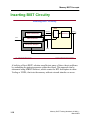
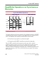
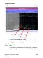
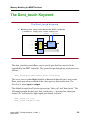
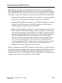
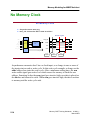
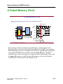
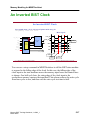
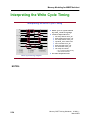
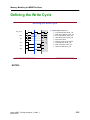
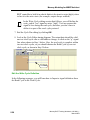
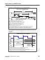
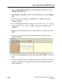
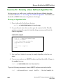
Memory Modeling for MBISTArchitect
When Memory clocking is set to anything other than -System, there will be a
MUX instantiated which will select between a system clock and a BIST-related
signal. This MUX will be very obvious when you use commands that place MUX
related RTL in the collar. Otherwise, it may be buried in the BIST controller RTL.
• When the SETup MEmory Clocking -Test command is specified, the BIST
clock will be sent to the BIST controller and directly to the MUX.
• When the SETup MEmory Clocking -Test INVERT command is specified,
the BIST clock will be routed to the BIST controller. It will be passed
through an inverter and then routed to the MUX.
• When the SETup MEMory Clocking -Controller command is specified, the
BIST controller will use internal logic to drive a signal that is to act as the
clock.That signal will be routed to the MUX. The BIST controller itself is a
synchronous, single-phase clock, design. So, it cannot change the state of
this clock signal any faster than once per BIST clock. So, the clock it
generates cannot be any faster than one-half the speed of the BIST clock
(one clock for going high, one-clock for going low). Depending on the
operation needed, the BIST controller may keep the output clock constant
for several BIST clock cycles. Often, this is to calculate and set up
conditions for a rising clock edge on the memory.
There is a separate command: SET COntroller Clock [-positive | negative] that can
be used in conjunction with the clock connection command to deal with memories
that lock their inputs on falling edges rather than rising edges. Also, the two
commands can be used to effect half-cycle phase shift which can overcome timing
violation issues. This is discussed later in this workbook.
Memory BIST Training Workbook, 8.2002_1
March 2002
5-13