1
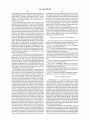
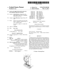
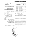
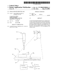
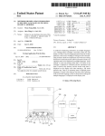
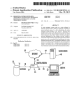
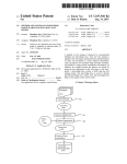
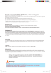
US008468900B2
(12) Ulllted States Patent
(10) Patent N0.:
Warhurst
(54)
(45) Date of Patent:
PIPETTE TIP POSITIONING FOR
MANUALLY_DIRECTED, MULTLCHANNEL
8,033,188
2005/0249635
2006/0048846
2007/0221684
ELECTRONIC PIPETTOR
_
B2
A1
A1
A1
2009/0074622 A1
(75)
lnvemori
Jllllall Warhurst, Ashland, MA (Us)
(73)
Assignee: Integra Biosciences C0rp., Hudson, NH
2009/0274587 A1
2011/0160909 A1 *
(Us)
_
(*)
_
Not1ce:
US 8,468,900 B2
_
_
10/2011 Kalmakis et al.
11/2005 Okun et al.
3/2006 Roenneburg
9/2007 Steinbrenner et al.
3/2009 Kalamakis et al.
11/2009 ButZ et al.
6/2011
Glauser et al. .............. .. 700/264
2011/0263627 A1
11/2011 W?fhufst et ?1~
2011/0268628 A1
11/20 11 Warhurst
_
Subject to any disclaimer, the term of th1s
patent is extended or adjusted under 35
Jun. 25, 2013
FOREIGN PATENT DOCUMENTS
WO
2009/130318
U-S-C- 15403) by 91 days-
10/2009
OTHER PUBLICATIONS
(21)
Appl_ No; 13/099,854
Rainin Pipetting 360° Simultaneous 96-Well pipetting, Fast manual
benchtop system, 2009 Rainin Instrument, LLC, PB-210 LIQ RevB,
(22)
Filed:
2 Pg$~
Rainin Pipetting 360° Liquidator 96, Manual benchtop pipetting
May 3, 2011
(65)
prior publication Data
D60. 8, 2011
system, 2008 Rainin Instrument, LLC, 9920-360 Rev. B, 16 pgs.
CyBiiWell Pipettor User Manual, Release Sep. 2008, 88 pgs.
Thermo Scienti?c Matrix Hydra II, Product Speci?cation, 2008
Related US. Application Data
Thermo Scienti?c Matrix PlateMate 2x3, Product Speci?cation,
US 2011/0296931101
Thermo Fisher Scienti?c, Inc., 2 pgs.
_ _
(60)
(51)
_
_
Thermo Scienti?c Matrix PlateMate Plus, Product Speci?cation,
3, 2010-
2007 Thermo Fisher Scienti?c, Inc., 2 pgs.
International Preliminary Report on Patentability, International
Patent Application No. PCT/US2011/034973, dated Nov. 6, 2012.
Int. Cl.
B01L 3/02
(52)
(2006.01)
US. Cl.
USPC
(58)
2007 Thermo Fisher Scienti?c, Inc., 2 pgs.
PrOVlslOnal apphcanon NO‘ 61/330,551’ ?led on May
* cited by examiner
..................................................... ..
73/864.25
_
_
_
Field of Classi?cation Search
Pr’mary Exammer * Robert R Raevls
None
See application ?le for complete search history.
(74) Attorney, Agent, or Firm *Andrus, Sceales, Starke &
SaWan: LLP
References Cited
(57)
ABSTRACT
A manually directed, multi-channel electronic pipettor
(56)
U.S. PATENT DOCUMENTS
5/1992 Fung et al.
includes a software biasing mode to assure proper alignment
over Wells in the 96-Well plate and the 384-Well plate. The
5,116,180 A
6,360,792 B1
3/2002 GanZ et al.
system also includes manual repositioning levers for nesting
6,601,433 B2 *
8/2003
Kriz et al. .................... .. 73/1.74
6,982,063
7,540,205
7,662,343
7,662,344
1/2006
6/2009
2/2010
2/2010
Hamel et al.
Nelson et al.
Mathus et al.
Mathus et al.
receptacles Which are customized for 96 Well-plates and 384
B2
B2
B2
B2
Well-plates respectively.
22 Claims, 6 Drawing Sheets
US. Patent
Jun. 25, 2013
30
52
Sheet 1 of6
US 8,468,900 B2
a
'0“
56
W24
58
32
5
12
14
29
28
27
20
FIG 1
16
US. Patent
Jun. 25,2013
Sheet 5 of6
US 8,468,900 B2
FIG. 4
FIG. 4A
FIG. 48
FIG. 4C
US. Patent
Jun. 25, 2013
Sheet 6 of6
ENTER DETENT WINDOW
EXIT DETENT WINDOW
FIG. 5
US 8,468,900 B2
US 8,468,900 B2
1
2
PIPETTE TIP POSITIONING FOR
contains a drive system to raise and loWer the pipetting head
MANUALLY-DIRECTED, MULTI-CHANNEL
to aspirate and dispense reagents and samples in the Well
ELECTRONIC PIPETTOR
plates or reservoirs set in the nesting receptacles on the deck.
FIELD OF THE INVENTION
The system also includes a drive system to move the toWer, as
Well as the pipetting head, in a horizontal or X-axis direction.
The control handle is preferably mounted to a load cell
attached to the pipetting head, although it may be mounted in
various other positions on the laboratory bench. The load cell
The invention relates to a manually directed, electronic
pipetting system having a pipetting head With a plurality of
pipetting channels, e.g., 96-channels, arranged in an array of
detects force exerted on the control handle and outputs cor
responding signals to the electronic motion control system. In
roWs and columns. In particular, the invention pertains to
methods of positioning the pipetting head for simultaneous
use, the user grabs the control handle in a manner similar to
aspiration and dispensing of liquid samples and reagents from
multi Well-plates.
When using a hand-held electronic pipettor. The user exerts
pressure on the control handle and in turn the load cell trans
mits signals to the electronic motion control system to move
BACKGROUND OF THE INVENTION
the multi-channel pipetting head relative to the Well-plates
and reservoirs on the deck. As mentioned, in the preferred
The assignee of the present application has ?led a co
embodiment, a motorized vertical drive mechanism raises
pending patent application entitled “Manually-Directed,
and loWers the pipetting head With respect to the Wellplate
Electronic Multi-Channel Electronic Pipetting System”,
Which Was ?led on even date hereWith, by Julian Warhurst,
Gary Nelson and Richard Cote, is based on US. Provisional
Application No. 61/330,541, ?led on May 3, 2010, and is
herein incorporated by reference. The assignee has also ?led
another co-pending patent application entitled “Unintended
Motion Control for Manually Directed Multi-Channel Elec
deck and a motorized horizontal drive mechanism moves the
20
toWer and the pipetting head laterally, both in response to
25
the control handle from left to right, the toWer along With the
pipetting head moves from left to right. If the user pulls the
control handle upWard or pushes doWnWard on the control
handle, the vertical drive mechanism raises or loWers the
sensed force exerted on the control handle. If the user presses
pipetting head accordingly.
tronic Pipettor, Which Was ?led on even date hereWith, by
Julian Warhurst and Richard Cote, is based on US. Provi
sional Application No. 61/3340,545, ?led on May 3, 2010,
and is also incorporated by reference herein. The present
invention pertains to a manually directed, multi-channel elec
30
tronic pipettor as Well, and in particular to features of the
motion control system that facilitate precise positioning of
the multi-channel pipetting head and the disposable pipette
tips for aspiration and dispensing of liquid samples and
1 1/ 856,231 by Gary E. Nelson, George P. Kalmakis, Kenneth
Steiner, Joel Novak, Jonathon Finger, and Rich Cote, ?led on
reagents into and from an array of Wells in a Wellplate.
As is knoWn in the art, a multi-Well plate is a ?at plate With
multiple Wells used as individual test tubes. The most com
mon multi Well-plates include 96-Wells or 384-Wells arranged
in a rectangular matrix. ANSI has set standardized dimen
35
sions and SBS footprints for Well-plates. For example,
40
Sep. 17, 2007, assigned to the assignee of the present appli
cation and incorporated herein by reference; and “Pipettor
SoftWare Interface”, application Ser. No. 11/856,232 by Gary
Nelson, George P. Kalmakis, Gregory Mathus, Joel Novak,
Kenneth Steiner and Jonathan Finger, ?led Sep. 17, 2007,
now US. Pat. No. 7,540,205, issued Jun. 2, 2009, and
96-Well plate has eight roWs and tWelve columns of Wells
centered 9 mm centerline-to-centerline. A typical 384-Well
plate includes sixteen roWs and tWenty-four columns of Wells
assigned to the assignee of the present application and incor
porated herein by reference. One of the bene?ts of this simi
larity is that users Which have become comfortable With the
assignee’s hand-held pipettors are able to easily cross-over to
With a centerline-to-centerline distance of 4.5 mm. Multi
Well-plates With 1536-Wells, and higher, are also available.
Some multi Well-plates are designed to hold larger volumes
than the standard multi Well-plate, yet maintain the standard
The control handle and menu-driven softWare program
ming interface is quite similar to the control handle and pro
gramming interface on assignee’s hand-held electronic pipet
tors, see e.g., US. Pat. No. 7,540,205, issuing Jun. 2, 2009,
entitled “Electronic Pipettor”, based on application Ser. No.
use the assignee’s manually directed, electronic multi-chan
45
nel pipetting system.
SUMMARY OF THE INVENTION
centerline-to-centerline dimensions. These Well-plates are
commonly called deep Well-plates. For purposes herein, the
term multi-Well plate to refer to both standard multi Well
50
plates and deep Well-plates. Assignee’s manually-directed,
Wellplate placed on the deck of a manually assisted, elec
tronic multi-channel pipetting system. As described in the
electronic multi-channel pipetting system, as described in the
above-incorporated patent applications, the preferred manu
ally directed, electronic multi-channel pipetting system has a
above incorporated patent applications, is designed to trans
fer liquid samples from an array of Wells in a standard multi
Well plate or deep Wellplate, or from a reagent reservoir to an
55
array of Wells in another standard Wellplate or deep Wellplate.
One of the advantages of the assignee’s manually directed,
electronic multi-channel pipetting system is the ability of the
user to move the pipetting head, and hence the disposable
pipette tips, in response to pressure exerted on the control
The invention pertains to a positioning system that facili
tates accurate alignment of pipette tips over the Wells in a
60
multi-channel pipetting head that is carried in a movable
carriage. The multiple channels on the pipetting head are
arranged in a tWo-dimensional array of roWs and columns,
preferably 96-channels arranged in a standard 8><12 array.
The system also includes a deck that has at least tWo Wellplate
nesting receptacles adapted to hold a multi-Well plate or a
handle. This feature of operation is signi?cantly different
sample reservoir. The pipetting head is preferably mounted to
than the operation of fully automated, high-throughput liquid
a toWer With the deck at the foot of the toWer. The system
includes a motorized Z-axis drive mechanism for raising and
handling systems. The multi-channel pipetting head in the
assignee’s manually directed system is mounted to a movable
carriage that is attached to a toWer. A deck having preferably
tWo Wellplate nesting receptacles is located in front of the
toWer and is accessible by the pipetting head. The toWer
65
loWering the pipetting head With respect to the deck. It also
includes the motorized X-axis drive mechanism for moving
the pipetting head laterally With respect to the deck. As
described in the above-incorporated patent applications, a
US 8,468,900 B2
3
4
control handle is mounted to the pipetting head carriage and
the pipetting head to the appropriate X-axis position to prop
erly align the pipette tips over the appropriate Wells in the 384
the pipetting head moves in response to force applied to the
control handle. The speed of the pipetting head in a given
direction is generally proportional to the amount of force
Well-plate. Preferably the system includes a sensor that senses
the Y-axis position of the nesting receptacle. If the nesting
receptacle is in a 96-Well position, the X-axis biasing posi
exerted on the control handle in the given direction as
detected by a load cell.
In accordance With the invention, the movement of the
tions Will be selected for a 96 Well-plate. If theY-axis position
for the nesting receptacle is set in either the 384-Well A
pipetting head in the X-direction for purposes of aligning the
multi-channel pipetting head (or in the vertical Z-axis direc
tion to facilitate proper height location of the pipetting head)
position or the 384-Well B position, the biasing positions in
the X direction Will be set for a 384 Well-plate.
The biasing mode can also be implemented in the vertical
Z-axis direction in order to facilitate proper height location of
can occur either in a free form mode or in a position biasing
mode. In the free form mode, the system generally alloWs
positioning of the pipetting head in the x-direction and in the
Z-direction in response to user force inputs. In the biasing
the pipette tips during the pipetting routine. This and other
mode, hoWever, the user still controls the position, but as a
draWings and description thereof.
aspects, and advantages of the invention Will be apparent to
those of ordinary skill in the art upon revieWing the folloWing
knoWn Wellplate position is approached, the pipetting head
Will tend to self-align to the center of the Wells in the under
BRIEF DESCRIPTION OF THE DRAWINGS
lying Well-plate. The biasing mode is implemented, prefer
ably, as a position dependent software bias to the force input
signals from the control handle. The biasing mode is also
quite helpful for touching off the tips against the sideWall of
FIG. 1 is a perspective vieW of a manually directed, multi
channel electronic pipetting system constructed in accor
dance With an exemplary embodiment of the invention.
the respective Wells after dispensing. Touching off is a com
monly used technique in pipetting to ensure that all of the
pipetting system illustrated in FIG. 1.
liquid is removed from the tip When dispensing. Without the
biasing mode, the accumulated force of 96 pipette tips touch
20
FIG. 2 is a front elevational vieW of the multi-channel
25
ing off simultaneously against a Wall of the Wells in a Well
plate can create instability.
If the user loads a 96-Well plate onto the nesting receptacle
on the deck, the user must ?rst align the pipetting head and
pipette tips With the 96-Wells in the plate before dropping
exemplary embodiment of the invention.
30
doWnWard into the Wells to aspirate or dispense. The biasing
mode assists the user to properly align the pipetting channels
centered over Wells in the Well-plate.
aspirating or dispensing from a 384-Well plate because the
35
96-Well plate. If desired, the biasing mode can be activated
independently for each nesting receptacle.
In the preferred version of assignee’s manually directed,
multi-channel electronic pipetting system, the pipetting head
moves only in the X-axis horiZontal and Z-axis vertical direc
tions, and not in a Y-axis horiZontal direction. Therefore, in
FIG. 3B is a block diagram shoWing an electromechanical
and softWare control loop similar to that shoWn in FIG. 3, but
also illustrating the use of a self-centering bias velocity equa
tion in accordance With a preferred embodiment of the inven
tion.
FIG. 4 is a schematic draWing illustrating pipette tips being
and tips. Alignment accuracy is particularly important When
dimension of the Wells is so much smaller than With a typical
FIG. 3A is a block diagram illustrating an electromechani
cal and softWare control loop used in accordance With an
40
FIGS. 4A-4C schematically illustrates the concept of
touching off as is accomplished in accordance With the pre
ferred embodiment of the invention.
FIG. 5 is a schematic draWing illustrating the operation of
an electronic time fader Which is used to smooth operation of
the system When in the biasing mode.
FIG. 6 is a schematic draWing illustrating the geometric
differences betWeen a 96-Well plate and a 384-Well plate.
order to accommodate aspiration and dispensing into the
Wells of 384 Well-plates, a desired embodiment of the inven
tion alloWs the nesting receptacles on the deck to be reposi
tioned in the horizontal Y-axis direction, preferably manually.
DETAILED DESCRIPTION
45
In this preferred embodiment of the invention, there are three
Y-axis positions for each of the Wellplate nesting receptacles
incorporated patent applications is shoWn in FIGS. 1 and 2.
Referring to FIGS. 1 and 2, the manually directed, multi
on the deck, namely a 384-Well A position, a 96-Well position
and a 384-Well B position. Each of these positions is selected
so that mounted pipette tips Will be aligned in the y-direction
With the centerline of the respective underlying Well on the
Well-plate, assuming that the Wellplate has standard dimen
sions. For example, When a 96-Well plate is placed in a nesting
receptacle positioned in the 96-Well position, the tips on the
pipetting head Will be properly aligned in the y-direction With
An embodiment of a manually directed, multi-channel
electronic pipetting system 10 as described in the above
channel electronic pipetting system 10 includes a multi-chan
50
nel pipetting head 12 having a plurality of pipetting channels
arranged in a tWo dimensional array of roWs and columns.
Normally, the pipetting head 12 Will include an array of 96-tip
?ttings. An array of pipette tips 14 are attached to the multi
channel pipetting head 12. The manually directed, multi
55
channel electronic pipetting system 10 includes a ?at deck 16
the centerline of the Wells in the 96 Well-plate. On the other
hand, a 384-Well plate contains 96 sets of 4 Wells arranged in
supporting a right nesting receptacle 18 and a left nesting
receptacle 20. The nesting receptacles 18, 20 are designed to
a 2x2 array in the x and y directions. If a 384-Well plate is
hold multi Well-plates or reservoirs in a knoWn location on the
placed in the Wellplate nesting receptacle, the receptacle is
positioned in the 384-Well A position to access the top tWo
Wells in the 2x2 array, and set to the 384-Well B position to
deck 16. In FIGS. 1 and 2, a 96-Well plate 26 is located in the
60
The pipetting head 12 is removably mounted to a carriage
access the bottom tWo Wells in the 2x2 array. The motoriZed
X-axis drive mechanism is used to move the pipetting head in
22 Which in turn is mounted to a toWer 24. A pipetting motor
the x-direction in order to position the respective pipette tips
over the selected Wells in the 384-Well A position or 384-Well
B position, as appropriate. The biasing mode as described
above is preferably activated to help the user better position
right nesting receptacle 18. A 384-Well plate 28 is located in
the left nesting receptacle 20.
65
located Within the carriage 22 drives the multi-channel pipet
ting head 12 to aspirate and dispense. A Z-axis drive mecha
nism moves the carriage 22 and the multi-channel pipetting
12 vertically With respect to the toWer 24 and the deck 16. An
US 8,468,900 B2
5
6
X-axis drive mechanism moves the tower 24 and the carriage
22 horizontally along an X-axis so that the pipetting head 12
and the array of tips 14 can be moved from a position corre
control handle 30 not only provides a handle for attachment to
the load cell 32 to control movement of the pipetting head, but
also preferably provides a user input interface. The control
handle 30 shown in FIGS. 1 and 2 includes an elongated body
adapted to be held in the hand of the user. A touch wheel
control 52 is designed to be operated by the user’ s thumb. The
sponding to the wellplate 26 in the ?rst nesting receptacle 18
on the deck 16 to various positions corresponding to the
wellplate 28 residing in the left side nesting receptacle 20.
The system 10 includes a control handle 30 preferably
mounted to the carriage 22 and preferably resembling a
handle for a handheld electronic pipettor. More speci?cally,
touch wheel control 52 is located below a dot matrix user
the control handle 30 is preferably mounted to a load cell 32
that is attached to the carriage 22. In use, the user grasps the
control handle 30 in the manner similar as when using a
handheld pipettor, and exerts pressure on the control handle
30 to move the carriage 22 and the pipetting head 12. The
vertical Z-axis motion and the horiZontal X-axis motion are
driven by independent motors under servo control. The con
trol handle 30 on the load cell 32 has two pairs of strain
control 52 and an ejector button 58. In this exemplary
embodiment, a printed circuit board with a dedicated micro
processor is located within the control handle 3 0, although the
tower 24 contains a larger main printed circuit board that
includes an additional main microprocessor. The circular
touchpad 52 translates rotational movement of the user’s
thumb (or ?nger) into cursor movements on the display 54 in
interface display 54. The preferred controller 30 also includes
a run button 56 which is located below the touch wheel
order to navigate menu driven software. The menu driven
gauges, one for vertical force distribution and one for hori
software is, in many respects, similar to the software dis
Zontal force distribution. The X-axis drive and the Z-axis
closed in co-pending application entitled “Pipettor Software
Interface”, application Ser. No. 11/856,232 by George Kal
drive operate independently and contemporaneously when a
20
component of force input is measured by each respective pair
makis et al., ?led Sep. 17, 2007, now U.S. Pat. No. 8,033,188,
issued Oct. 11, 2011, assigned to the assignee of the present
application and incorporated herein by reference. As men
of strain gauges. The control handle 30 preferably also
includes a user interface for controlling pipetting functions
such as aspirating and dispensing.
The use of the controller 30 as well as the overall operation
25
tioned previously, the software provides graphic displays for
adjusting volume, relative pipetting speed, pace and count for
of the system 10 is intended to replicate the natural hand
the various program pipetting procedures. The software also
motion of a user using a conventional handheld pipettor.
However, with a conventional handheld pipettor, a user would
not be able to reliably use a 96-channel pipetting head in part
preferably provides multiple programmable pipetting modes
because of alignment issues. It would be extremely di?icult to
properly align all 96 pipette tips with a detached handheld
based on predetermined algorithms, such as pipette, repeat
30
pipette, sample dilute, pipette/mix, manual pipette, reverse
pipette, variable dispense, variable aspirate, sample dilute/
mix, and serial dilution. These functional modes are based
pipettor.
upon predetermined algorithms embedded in the software to
The manually directed, multi-channel electronic pipetting
implement respective, well known pipetting procedures,
system 10 must not only be capable of transferring ?uids from
and to selected locations, but must also provide for the prac
tical and convenient attachment and ejection of the pipette
although various parameters such as volume, speed, pace,
count, direction and mixing are available for programming
and editing for the user. In addition, the preferred software
35
tips. The preferred tip attachment and ejection mechanism is
disclosed in detail in the above incorporated patent applica
also includes a custom programming mode in which the user
can create custom pipetting procedures based on the steps of
aspirating, mixing, dispensing and purging. The preferred
tions entitled “Manually-Directed, Multi-Channel Electronic
Pipetting System”, U.S. patent application Ser. No. 13/099,
40
782, ?led May 3, 2011 and “Unintended Motion Control for
Manually Directed Multi-Channel Electronic Pipettor”, U.S.
patent application Ser. No. 13/099,953, ?led May 3, 2011,
assigned to the assignee of the present application and incor
porated herein by reference. Brie?y, the pipetting head 12
with the array of tip ?ttings 36 is aligned precisely over the tip
software also includes other features as well.
While the touch wheel control 52 and the display 54 are
generally used to program the pipetting system, the display 54
45
is also used to show progress or status during an implemented
pipetting routine. In this regard, the run button 56 is used to
activate the system to aspirate or dispense, etc. in accordance
with the pipetting protocol on the display 54. For example,
container using the X-axis horiZontal drive mechanism. Then,
consider a situation in which the pipette tips 14 are attached to
the pipetting head 12 ready for use and a reagent reservoir is
the Z-axis vertical drive mechanism is used to lower the
50
placed within nesting receptacle 20 and a 96-well plate 26
with samples is placed in nesting receptacle 18, and it is
?uids. For tip attachment as with regular motion control, the
general horiZontal and vertical motion of the carriage 22 and
pipetting head 12 is controlled by the user by holding the
controller 30 in their palm and applying pressure in the appro
priate direction to position the pipetting head 12 over the tray
55
desirable in accordance with a programmed protocol to trans
fer 20 pl of the reagent from the reservoir into each of the
96-wells in the wellplate 26. The user grasping the control
handle 30 will ?rst direct the carriage 22, pipetting head 12
and pipette tips 14 over the reservoir located in nesting recep
of pipette tips 14. Precise alignment necessary for tip attach
60
carriage 22 and the tip ?ttings with su?icient force to attach
the array of pipette tips 14. The carriage 22 and the pipetting
head 12 are then raised using the Z-axis horizontal drive
mechanism to remove the tips 14 from the tip container. The
tip container is removed from the nested receptacle 18 and
replaced with a wellplate or reservoir in order to transfer
tacle 20. The display 54 may illustrate an instruction such as
ment would of course be quite dif?cult; however, the biasing
motion control software described below facilitates precise
“aspirate 20 pl”. The user will then lower the pipette tips 14
into the liquid in the reservoir by placing downward pres sure
on the control handle 3 0. Then, in order to aspirate 20 pl of the
reagent into each pipette tip 14, the user will press run button
56 to activate the pipetting stepper motor to aspirate 20 pl of
reagent into each pipette tip. The user will then lift the ?lled
alignment.
pipette tips 14 from the reagent reservoir by pulling upward
The preferred control handle 30 is the same or quite similar
to that disclosed in issued U.S. Pat. No. 7,540,205 entitled
“Electronic Pipettor” by Gary Nelson et al. issued on Jun. 2,
2009, and herein incorporated by reference. The preferred
on the control handle 30. The next instruction on the display
65
54 may be “dispense 20 pl”. The userwill then move the ?lled
pipette tips over the wellplate 26 in the other nesting recep
tacle 18, and align the pipette tips over the appropriate wells
US 8,468,900 B2
7
8
in the Wellplate 26 by pressing against the control handle 30.
that the respective servo motor 74, 108 should attempt to
The user Will then loWer the ?lled tips over the Wells, and
press run button 56 to instruct the pipettor stepper motor to
PID controller.
dispense the liquid in the pipette tips 14.
The actual motor position is measured by accumulating the
output of the digital encoder 156 attached to the respective
achieve, i.e. the classic target position for an industry standard
The general aspects of the motion control system, in free
form mode, are described beloW in connection With FIG. 3A.
servo motor 74, 108, see reference number 158. The actual
The servo motor 108 for horizontal movement and the servo
position is then compared to the target position, see reference
motor 74 for vertical movement are preferably brushless
number 148, and the output is a position error value in line
149. The position error value in line 149 is passed through a
3-phase motors With encoders operated With identical and
independent control loops. Both vertical motion and horizon
tal motion can operate simultaneously depending on the force
proportional-integral-derivative ?lter 150, Which calculates
the desired motor output poWer. The desired motor output
poWer signal is then fed to a 3-phase motor driver 152 Which
converts the signal to a pulse Width modulation signal that is
imparted on the control handle 30. FIG. 3A illustrates the
preferred control loop in free form mode, When the user
ampli?ed through a 3-phase FET bridge and then fed to the
imparts a force on the control handle 30. The detected hori
zontal component of the force as Well as the detected vertical
component force is characterized by the load cell 128 or a
signal that is initially ampli?ed by a pre-ampli?er 130 to a
level suitable forA/D conversion. The voltage signal from the
pre-ampli?er 130 is converted into a digital force value pref
erably at a rate of 100 samples/second. The digital output
signal from the A/ D converter 132 is then null corrected,
servo motor 74, 108. The result of this control loop is that the
motion of the pipettor head 112 tracks the hand motion
imparted by the user on the control handle 30, With a natural
feel and With end travel limits imposed in a gradual matter.
Use of the biasing mode during system operation is noW
20
reference number 134. The null correction feature alloWs the
load cell output to drift over time and/ or have poor initial zero
output. To determine the null value 136, the user is asked to
remove their hand from the control handle 30, the A/ D con
verter output 132 is then measured, and if stable that value it
is stored as the null value 136. During normal operation, the
null value is subtracted from the A/D converter output 132
and the output of the null subtraction 134 is in the range of
25
the amount of residual liquid left Within the tip When making
30
+127 to —l27 With zero corresponding to no input from the
user. The null correction feature is useful When the load cell
32 is overloaded due to misuse or accidental impact Which
may cause its “zero” value to change. Preferably, the null
value Will be reset Whenever the system is re-initialized.
The null-corrected user force value is then passed through
an averaging ?lter and integrator 138. The averaging ?lter and
integrator 138 has tWo functions. First, since the load cell is
subject to some vibration and noise during normal operation,
the averaging ?lter 138 smoothes out the signal. Second, the
integrator reduces the force that the user must impart by
accumulating the force input over time. This provides the
35
a ?nal dispense, and in turn improves the accuracy of the
dispensed amount. Therefore, even Within the dimensions of
a single Well in a Well-plate, it is desirable that the pipetting
head 12 be capable of positioning in a Wide range of horizon
tal increments With the mo st common being center alignment
and a small left or right deviation as shoWn in the touching off
position in FIGS. 4A and 4B. Accurate positioning of the
pipette tips in the Well of a Wellplate requires precise intricate
positioning.
Referring to FIG. 4, positioning the pipette tips over the
appropriate Wells in the Wellplate requires the user to move to
a horizontal position Within :1 or a feW mm for some of the
40
handheld controller 30 With a light feel and imparts a sensa
tion of inertia Which has been found to be desirable. The
output from the averaging ?lter and integrator 138 is the
discussed. Referring to FIG. 4, consider moving the pipettor
head 12 from a plate 26 in one of the nesting receptacles 18 to
another plate 28 in the other nesting receptacle 20. The user
can position the pipette tips 14 over the center of the Wells, or
in some cases move the tips to touch the sides of the respective
Well to alloW liquid to How from the tip doWn the side of the
Well. In the art this is called touching off, and it helps to reduce
multi Well-plates that are in use today. The pipette tips may be
damaged if they contact the plate With su?icient force. The
Weight of a 96-channel pipetting head makes it particularly
easy to crash the tips into the plates. This can be frustrating for
the user, and can also cause unnecessary tip replacement if the
45
tips are damaged. To improve this situation, the motion con
requested speed value, line 140. The requested speed value is
trol loop can be modi?ed to give an arti?cial feel or bias When
a speed limiting function, Which is designated in FIG. 3A as
block 142. The purpose of the speed limiting function 142 is
to prevent crashing in the either vertical or horizontal direc
the user approaches the centerline target position. This arti
tion at the end of the travel range. Crashing may cause dam
?cial feel causes the user to feel a sensation as if a ball is
50
age, and also provides undesirable sensation. The requested
line of the Well, the motion controller self-centers the pipette
tip over the Well, see FIG. 4C. Once the pipette tip is centered
speed value 140 is limited at the end of the mechanical travel
range such that the speed is linearly reduced to zero as the end
of the mechanical travel range is reached. To do this, the speed
limiter 142 is updated With the actual position of the pipetting
over the Well, light hand force inputs are insuf?cient to move
the pipettor out of position horizontally. If the user pushes
55
the user’s ability to accurately touch off the pipette tips
60
A control loop for implementing the biasing mode is shoWn
The adjusted speed value from the speed limiter 142 is then
updated, e. g. 1,000 times/ second, and represents the position
against the side of the Well. This mode of motion control is
referred herein as the biasing mode.
in FIG. 3B. The control loop shoWn in FIG. 3B is quite similar
to that shoWn in FIG. 3A except that it contains block 160
the last 10 mm on either end of travel.
integrated, eg at a rate of 1 kHz, to calculate a target position,
see reference numbers 144 and 146. The target position is
harder, the user Will start to overcome the self-centering bias
and Will be able to perform touch off operations. In this
situation the self-centering bias resisting the user enhances
head from the encoder 156 and position counter 158 for the
respective motor 74, 108. Line 143 illustrates the actual posi
tion data being fed back to the speed limiter 142. For the
horizontal axis, the total travel is approximately 1 50 mm With
the speed limiter coming into effect during the last 10 mm on
either end of travel. For the vertical axis, the total travel is
approximately 250 mm With the limiter coming into effect in
falling into a hole as shoWn in FIGS. 4A-4B.
As the user approaches the target position over the center
65
representing self-centering bias velocity equation, and sum
ming junction 162 Which sums the position limited speed
command from block 142 With the velocity bias value from
block 160.
US 8,468,900 B2
10
The self-centering bias velocity algorithm contains equa
Well, it passes beyond a half Well Width and the fade times
start to count doWn. The biasing velocity gradually decreases,
tions that convert the horizontal position information of the
pipetting head into a left or right velocity bias value. In its
simplest form, there are a series of decision statements based
on the distance from the center line position of the Well-plates
in the nesting receptacles 18 or 20:
Where:
Which avoids the undesirable feel leaving the center of the
Well.
Although described above With respect to biasing With
respect position along the X-axis, biasing can also be accom
plished in the vertical Z-axis in generally the same manner.
Referring noW to FIGS. 6 and 1, the nesting receptacles 18,
20 can each be independently positioned in the Y-axis hori
Zontal direction. TheY-axis horiZontal direction is orthogonal
XIcurrent position Where positive positions are to the right
Xcl:center of the left position,
XcrIcenter of right position
to the Z-axis vertical direction and to the X-axis horizontal
direction in Which the pipetting head 12 and carriage 22 move
With respect to the deck 16. Preferably, a lever 27, 29 on each
Xh:half Well Width distance (4.5 mm for 9 mm Wells)
SIbias velocity
Vadd:velocity to be added to the users hand controller
of the nesting receptacles 18, 20 is used to manually reposi
input
tion the nesting receptacles in one of three Y-axes locations.
The three Y-axes locations comprise a 96-Well position, and a
384-Well A position and a 384-Well B position. When the
Detecting Within the Well to the left of the left position:
Detecting Within the Well to the right of the left position:
Detecting Within the Well to the left of the left position:
20
nesting receptacle 18 is located in the 96-Well position (as is
receptacle 18 in FIG. 1), the pipette tips 14 mounted on the
pipetting head 12 Will align With theY-axis centerline for each
25
Well in a 96 Well-plate. The spacing betWeen Wells in a
96-Well plate is 9 mm. The spacing betWeen Wells in a 384
Well plate is 4.5 mm. As illustrated in FIG. 6, each Well
(phantom) in a 96-Well plate 226 corresponds generally to a
group of four Wells in a 384-Well plate 228. The 384-Well A
Detecting Within the Well to the right of the left position:
If (X>Xcr) and (X<Xcr+Xh) then Vadd:—S If none of
these rules are true then Vadd:0
The above four rules are mutually exclusive; only one can
be true at a time. These simple functions do achieve the
intended effect. HoWever, there is an undesirable effect
position for the nesting receptacle repositions the nesting
receptacle 20 so that the top roW of Wells in a 384-Well plate
caused by Vadd rapidly changing from +/—S to Zero When the
Will align along the Y-axis With the pipette tips on the pipet
ting head 12. The 384-Well B position corresponds to the
user moves out of the Well and this effect causes a noticeable
“jump” in the hand controller feel. To eliminate this jump, the
30
position in Which the second roW of Wells in the 384-Well
equations are modi?ed to add a time delay that fades the Vadd
up or doWn as the user enters or exits the biasing detent. The
plate align along the Y-axis With pipette tips on the pipetting
head 12. In FIG. 1, nesting receptacle 20 is in the 384-Well b
time fades is graphically depicted in FIG. 5. The time delay is
position. An array of 96-pipette tips on the pipetting head 12
a 1000 ms delay that counts up or doWn in 1 ms increments. If
pipetting head is Within the left detent (on either the left or
right of center) then the time delay counts up. If not, it counts
doWn. For example the folloWing equations are executed
can therefore access all of the Wells in a B Well-plate.
35
every 1 ms:
set the right side nesting receptacle 18 With the 96-Well plate
in the 96-Well plate position using lever 27. Then the user
40
If (FadeTImer < 1000) then FadeTimer = FadeTimer+l
Else
If (FadeTImer > 0) then FadeTimer = FadeTimer-l
Endif
45
The original equations are modi?ed and the FadeTimer
value is multiplied by S. In addition the default setting of S
back to Zero is eliminated; instead it remains at the last value:
Detecting Within the Well to the left of the left position:
50
If (X<Xcl) and Q(>Xcl-Xh) then Vadd:S*FadeTimer/
Detecting Within the Well to the right of the left position:
If (X>Xcl) and (X<Xcl+Xh) then Vadd:—S*FadeTimer/
55
Detecting Within the Well to the left of the left position:
If (X<Xcr) and (X>Xcr-Xh) then Vadd:S*FadeTimer/
1000
Detecting Within the Well to the right of the left position:
If (X>Xcr) and Q(<Xcr+Xh) then Vadd:—S*FadeTimer/
60
1000
Thus When the user initially moves the pipetting head
Within a half Well Width of the center of the Well, the fade
timer gradually counts from 0 to 1000 ms over the period of 1
second and increases the biasing velocity S gradually, avoid
ing an undesirable feel entering the center of a Well. As the
user moves the pipetting head aWay from the center of the
Would exert force on the control handle to move the pipetting
head over the 96-Well plate 26 to approximately align the
channels in the pipetting head With the Wells in the 96 Well
plate. If the biasing mode is activated, the motion control
system Will bias the X-axis position of the pipetting head 12
toWards a predetermined X-axis position in Which the
96-channels on the pipetting head 12 are accurately aligned
over the 96-Wells in the Wellplate 26 set in the right side
nesting receptacle 18. The user Will then use the control
handle 30 to loWer the carriage 22 so that the pipette tips
reside Within the liquid in the Wells of the 96-Well plate 26,
and operate the controller 30 to aspirate a desired amount of
liquid into the array of pipette tips 14. The user Will then exert
force on the control handle 30 to move the pipetting head 12
upWard and over toWards the 384-Well plate 28 located on the
1000
1000
In order to transfer ?uid from Wells in a 96-Well plate 26 in
the right side nesting receptacle 18 to the Wells in a 384-Well
plate 28 on the other nesting receptacle 20, the user Would ?rst
other nesting receptacle 20 on the deck 16. Before dispensing,
the user Will set the nesting receptacle 20 to the 384-Well A
position or the 384-Well B position. Then, the user Will con
tinue to exert force on the control handle 30 in the X-axis
direction to move the 96-channel pipetting head 12 into
approximate alignment over a ?rst set of 96-Wells in the 384
Well-plate, eg a ?rst quadrant. The control system Will bias
the X-axis position of the pipetting head 12 automatically to
65
a predetermined X-axis position in Which the 96-channels on
the pipetting head are precisely aligned With a ?rst set of
96-Wells in the 384 Well-plate. The user Will then dispense a
desired amount of sample or reagent into the ?rst set of Wells.
The user Will then use the control handle 30 to move the
US 8,468,900 B2
11
12
96-pipette tips from the ?rst set of 96-Wells in the 384-Well
corresponding to the 384-Well A position for the nesting
2. The method of ali gning a multi-channel pipetting head in
a manually directed electronic multi-channel pipetting sys
tem as recited in claim 1 Wherein the system comprises
receptacle 20. Again, the biasing algorithm Will help facilitate
motion control softWare containing X-axis alignment biasing
plate over to a second set of 96-Wells in the 384-Well plate still
precise alignment of the 96-pipette tips over the second set of
96-Wells in the 384-Well plate. The user Will then reposition
the nesting receptacle 20 in the Y-axis direction to the other
384-Well position, eg to the 384-Well B position in order to
data Which biases X-axis positioning of the pipetting head in
part as a function of the position of the pipetting head.
3. The method of ali gning a multi-channel pipetting head in
a manually directed electronic multi-channel pipetting sys
tem as recited in claim Wherein the system further comprises
align the 96-channels in the pipetting head 12 With a third set
of 96-Wells in the 384-Well plate 28. Note that for this step it
means for selectively activating the X-axis position biasing
for each Wellplate nesting receptacle on the deck.
may not be necessary for the user to move the pipetting head
in the X-axis direction. After dispensing liquid into the sec
4. The method of ali gning a multi-channel pipetting head in
a manually directed electronic multi-channel pipetting sys
ond and third set of 96-Wells, the user Will then most likely use
the control handle 30 to move the pipetting head 12 in the
X-axis direction to approximate alignment over a fourth set of
tem as recited in claim 1 Wherein at least one Wellplate nesting
receptacle on the deck can be repositioned in a Y-axis direc
96-Wells in the 384-Well plate 28. Again, the biasing algo
rithm Will facilitate precise alignment of the pipette tips 14
tion that is orthogonal to the Z-axis direction and X-axis
direction, and the method further comprises the step of repo
over the fourth set of 96-Wells in the 384-Well plate prior to
dispensing the ?nal amount of liquid in the pipette tips into
the respective Wells. The user may choose to touch off the tips
in this fourth and ?nal set of Wells as described above With
respect to FIG. 4. The speci?c order in Which the steps are
accomplished is not critical to implementing the invention.
Note that vertical biasing positions can be used to dictate
20
preferred dispensing locations and/or preferred heights for
25
ment over Wells in the Wellplate set Within one of the Wellplate
moving the pipette tips from one Well to another. As men
tioned, it is preferred that the system be able to sense the
a 384-Well A position, a 384-Well B position and a 96-Well
appropriate biasing positions depending on Whether the
30
Also, the pipetting head 12 is preferably replaceable, and its
exact positioning Within the carriage 22 may vary from head
to head. The system preferably includes sensors to signal that
the pipetting head 12 has been mounted in a proper position
Within the carriage 22. In addition, it is desirable for the
nesting receptacles on the deck.
5. The method of ali gning a multi-channel pipetting head in
a manually directed electronic, multi-channel pipetting sys
tem as recited in claim 4 Wherein the Wellplate nesting recep
tacle may be positioned in three Y-axis locations comprising
position.
position of the levers 27 and 29, and therefore provide the
levers 27, 29 are set for a 96-Well plate or a 384-Well plate.
sitioning the Wellplate nesting receptacle in the Y-direction
prior to moving the pipetting head into approximate align
6. The method of ali gning a multi-channel pipetting head in
a manually directed electronic multi-channel pipetting sys
tem as recited in claim 5 further comprising the steps of:
setting a 96-Well plate in one of the nesting receptacles on
the deck;
positioning the nesting receptacle on the deck in the
35
96-Well position;
exerting force on the control handle to move the pipetting
softWare on the system to alloW the user to adjust the center
head over the Wellplate in the nesting receptacle to
line position for a 96-Well plate and/or a 384-Well plate.
approximately align the channels in the pipetting head
What is claimed is:
1. A method of aligning a multi-channel pipetting head in a
40
manually directed electronic pipetting system, Wherein the
manually directed electronic pipetting system comprises:
a multi-channel pipetting head carried in a movable car
riage, the multiple channels in the pipetting head being,
arranged in a tWo-dimensional array of roWs and col
45
umns;
a deck having at least tWo Wellplate nesting receptacles
the deck;
adapted to hold a multi Wellplate or reservoir;
a. motorized Z-axis drive mechanism for raising and loW
ering the pipetting head With respect to the deck;
50
a motoriZed X-axis drive mechanism for moving the pipet
to move the pipetting head into approximate alignment
a control handle mounted such that the multi-channel
pipetting head moves in response to force applied to the
over a ?rst set of 96 Wells in the 384 Well-plate; and
55
of detected force exerted on the control handle in said
given direction;
the method of aligning; the multi-channel pipetting head
comprising the steps of:
0
exerting force on the control handle in a given direction to
move the pipetting head in the given direction in order to
move the channels on the pipetting head into approxi
mate alignment With Wells in a Wellplate set Within one
of the Wellplate nesting receptacles on the deck; and
biasing the X-axis position of the pipetting head to a pre
determined X-axis position.
positioning the nesting receptacle on the deck in the 384
Well A position;
exerting force on the control handle in the X-axis direction
ting head laterally With respect to the deck; and
control handle and the speed of the pipetting head in a
given direction is generally proportional to the amount
With the Wells in the 96 Well-plate;
biasing the X-axis position of the pipetting head toWards a
predetermined X-axis position in Which the 96-channels
on the pipetting head are accurately aligned With the
96-Wells in the Wellplate set in the nesting receptacle.
7. The method of ali gning a multi-channel pipetting head in
a manually directed electronic multi-channel pipetting sys
tem as recited in claim 5 further comprising the steps of:
setting a 384-Well plate in one of the nesting receptacles on
biasing the X-axis position of the pipetting head to a pre
determined X-axis position in Which the 96-channels on
the pipetting head are precisely aligned With the ?rst set
of 96 Wells in the 384-Well plate set in the nesting recep
tacle.
8. The method of aligning the channels in a multi-channel
pipetting head in a manually directed electronic multi-chan
nel pipetting system as recited in claim 7 further comprising
the steps of:
exerting force on the control handle in the x-direction to
move the pipetting heat into approximate alignment
65
With a second set of 96 Wells in the 384 Well-late; and
biasing the X-axis position of the pipetting head toWard a
predetermined X-axis position in Which the 96-channels
US 8,468,900 B2
14
13
means for biasing the X-axis position of the pipetting head
toWards a predetermined position selected to align the
in the pipetting head are aligned precisely With a second
set of 96 Wells in the 384-Well plate set in the nesting
receptacle.
multiple channels in the pipetting head over Wells in a
9. The method of aligning a multi-channel pipetting, head
in a manually directed electronic multi-channel pipetting sys
tem as recited in claim 8 further comprising the steps of:
15. A system as recited in claim 14 further comprising
repositioning the nesting receptacle in the Y-axis direction
means for selectively activating the X-axis position biasing
Wellplate set Within one of the Wellplate nesting recep
tacles on the deck.
into the 384-Well B position in order to align the
means.
96-channels in the pipetting head With a third set of 96
16. A system as recited in claim 15 Wherein said selective
activation means is able to selectively activate said X-axis
Wells in the 384-Well plate set in the nesting receptacle.
10. The method of aligning a multi-channel pipetting head
in a manually directed electronic multi-channel pipetting sys
biasing means independently for each of the Wellplate nesting
receptacles.
tem as recited in claim 9 further comprising the steps of:
exerting force on the control handle in the X-axis direction
17. A system as recited in claim 14 Wherein at least one of
the Wellplate nesting receptacles on the deck is movable in a
Y-axis direction that is orthogonal to the Z-axis direction and
the X-axis direction.
18. A system as recited in claim 17 Wherein the Well
to move the pipetting head into approximate alignment
over a fourth set of 96 Wells in the 384-Well plate set in
the nesting receptacle; and
biasing the X-axis position of the pipetting head toWard a
predetermined X-axis position in Which the 96-channels
nesting receptacle can be positioned in three Y-axis positions
20
on the pipetting head are aligned With the fourth set of
96-Wells in the 384-Well plate set in the nesting recep
tacle.
11. The method of aligning a multi-channel pipetting head
in a manually directed electronic multi-channel pipetting sys
tem as recited in claim 7 further comprising the step of:
19.A method of dispensing liquid in disposable pipette tips
into Wells in a Wellplate set in a manually directed electronic
pipetting system, Wherein the manually directed electronic
25
riage, the multiple channels in the pipetting head being
into the 384 Well B position in order to align the 96-Wells
in the pipetting head With a second set of 96 Wells in the
384-Well plate set in the nesting receptacle.
arranged in a tWo-dimensional array of roWs and col
30
35
over a third set of 96 Wells in the 384-Well plate set in the
a plurality of disposable pipette tips mounted to the pipet
ting head in order to aspirate and dispense liquid;
a deck having at least one Wellplate nesting, receptacles
adapted to hold a multi Wellplate or reservoir;
a Wellplate set Within the Wellplate nesting receptacle on
the deck for receiving in its respective Wells liquid dis
a motoriZed Z-axis drive mechanism for raising, and loW
ering the pipetting head With respect to the deck;
40
a motorized X-axis drive mechanism for moving the pipet
ting head laterally With respect to the deck; and
receptacle.
13. The method of aligning a multi-channel pipetting head
in a manually directed electronic multi-channel pipetting sys
tem as recited in claim 12 further comprising the step of
umns;
pensed from the disposable pipette tips;
nesting receptacle; and
biasing the X-axis position of the pipetting head toWard a
predetermined X-axis position in Which the 96-channels
in the pipetting head are aligned accurately over the third
set of 96 Wells in the 384-Well plate set in the nesting
pipetting system comprises:
a multi-channel pipetting head carried in a movable car
repositioning the nesting receptacle in the Y-axis direction
12. The method of aligning a multi-channel pipetting head
in a manually directed electronic multi-channel pipetting sys
tem as recited in claim 11 further comprising the steps of:
exerting force on the control handle in the X-axis direction
to move the pipetting head into approximate alignment
comprising a 384-Well A position, a 384-Well B position and
a 96-Well position.
a control handle mounted such that the multi-channel
pipetting head moves in response to force applied to the
control handle and the speed of the pipetting head in a
45
repositioning the nesting receptacle in the Y-axis direction
given direction is generally proportional to the amount
of detected force exerted on the control handle in said
given direction;
into the 384-Well A position in order to align the 96-Wells in
a multi-channel pipetting head carried in a movable car
the method of dispensing liquid in the disposable pipette
tips into corresponding Wells in the Wellplate compris
ing the steps of:
a) aligning the disposable pipette tips over the respective
Wells in the Well-plate and biasing the X-position of the
riage, the multiple-channels being arranged in a tWo
pipetting head to a predetermined X-axis position over
the pipetting head With a fourth set of 96 Wells in the 384-Well
plate set in the nesting receptacle.
14. A manually directed electronic multi-channel pipetting
50
system comprising:
dimensional array of roWs and columns;
a deck having at least tWo Wellplate nesting receptacles
55
adapted to hold a multi Wellplate or reservoir;
a motoriZed Z-axis drive mechanism for raising and loW
c) exerting su?icient force on the control handle in order to
overcome the biasing and move the pipette tips simulta
ering the pipetting head With respect to the deck;
60
neously toWards the Wall of the corresponding Wells in
order to touch of the respective pipette tips against the
65
20. The method of dispensing liquid from the disposable
pipette tips into the respective Wells of the Wellplate as recited
in claim 19 Wherein the X-axis position of the pipetting head
is biased to a predetermined X-axis position that corresponds
a motoriZed X-axis drive mechanism for moving the pipet
ting head laterally With respect to the deck;
Well sideWalls.
a control handle mounted to the movable carriage;
means for moving the movable carriage and the pipetting
head in response to the force applied to the control
handle such that the speed of the pipetting head in a
given direction is generally proportional to the amount
of detected force exerted on the control handle in said
given direction; and
the respective Wells;
b) simultaneously dispensing the liquid in the respective
pipette tips into the corresponding Wells;
to the centerline of the respective Wells in the Wellplate on the
deck.
US 8,468,900 B2
15
16
21. A method of vertically aligning a multi-channel pipet
ting head at a desired height, in a manually directed electronic
pipetting system, Wherein the manually directed electronic
pipetting system comprises:
a multi-channel pipetting head carried in a movable car
riage, the multi-channels in the pipetting head being
arranged in a tWo-dimensional array of roWs and col
umns;
a deck having at least tWo Wellplate nesting receptacles
adapted to hold a multi Wellplate or reservoir;
a motoriZed Z-axis drive mechanism for raising and loW
ering the pipetting head With respect to the deck; and
a control handle mounted such that the multi-channel
pipetting head moves in response to force applied to the
control handle and the speed of the pipetting head in a
given direction is generally proportional to the amount
of detected force exerted on the control handle in said
given direction;
the method of vertically aligning the multi-channel pipet
ting head at a desired height comprising the steps of:
20
exciting force on the control handle in a given direction to
move the pipetting head up or doWn toWards the desired
vertical position; and
biasing the Z-axis position of the pipetting head to a pre
determined Z-axis position.
25
22. The method of vertically aligning a multi-channel
pipetting head as recited in claim 21 Wherein the system
comprises motion control software containing Z-axis align
ment biasing data Which biases Z-axis in positioning of the
pipetting head in part as a function of the position of the
pipetting head.
30