1
DEVELOPMENT TOOLS
The
Insider’s Guide
To The
STR91x ARM®9
Based Microcontroller
An Engineer’s Introduction To The STR91x Series
www.hitex.com
Published by Hitex (UK) Ltd.
ISBN: 0-9549988 5
First Published June 2006
Hitex (UK) Ltd.
Sir William Lyons Road
University Of Warwick Science Park
Coventry, CV4 7EZ
United Kingdom
Credits
Authors:
Illustrator:
Trevor Martin & Michael Beach
Sarah Latchford
Editor:
Cover:
Michael Beach
Wolfgang Fuller
Acknowledgements
The authors would like to thank Matt Saunders of ST Microelectronics for his assistance in compiling this book.
© Hitex (UK) Ltd., 01/11/2006
All rights reserved. No part of this publication may be reproduced, stored in a retrieval system or transmitted in
any form or by any means, electronic, mechanical or photocopying, recording or otherwise without the prior
written permission of the Publisher.
Contents
1
Chapter 1: The ARM9 CPU Core
9
1.1 Outline ............................................................................................. 9
1.2 ARM966E-S .................................................................................... 9
1.3 CPU Architecture ............................................................................ 9
1.4 The Pipeline .................................................................................. 10
1.5 Registers ....................................................................................... 11
1.5.1 Current Program Status Register.................................................. 12
1.6 Exception Modes........................................................................... 14
1.7 ARM9 Instruction Set .................................................................... 17
1.7.1 Branching ...................................................................................... 18
1.7.2 Data Processing Instructions ........................................................ 19
1.7.2.1 Copying Registers.................................................................. 20
1.7.2.2 Copying Multiple Registers .................................................... 20
1.8 Swap Instruction............................................................................ 21
1.9 Modifying The Status Registers .................................................... 21
1.10 Software Interrupt.......................................................................... 22
1.11 MAC Unit....................................................................................... 22
1.12 DSP Extensions ............................................................................ 23
1.13 THUMB Instruction Set ................................................................. 23
1.14 Summary....................................................................................... 25
2
Chapter 2: Software Development
28
2.1 Outline ........................................................................................... 28
2.2 The Development Tools ................................................................ 29
2.2.1 HiTOP Debugger & IDE ................................................................ 29
2.2.2 Which Compiler?........................................................................... 29
2.2.3 DA-C.............................................................................................. 29
2.2.4 TESSY........................................................................................... 29
2.3 Startup Code ................................................................................. 30
2.4 The ARM Procedure Call Standard (APCS) ................................. 33
2.5 Interworking ARM and THUMB..................................................... 34
2.6 STDIO Libraries ............................................................................ 34
2.7 Accessing Peripherals................................................................... 34
2.8 Interrupt Service Routines............................................................. 35
2.9 Software Interrupt.......................................................................... 36
2.10 In-Line Functions........................................................................... 37
2.10.1 Inline Assembler............................................................................ 37
2.11 Linker Script Files.......................................................................... 37
2.12 C++ support .................................................................................. 39
2.13 Hardware Debugging Tools .......................................................... 40
2.14 Important ....................................................................................... 41
2.15 Embedded Trace Module.............................................................. 41
2.16 Summary....................................................................................... 42
3
3.1
3.2
3.3
3.3.1
3.4
Chapter 3: System Peripherals
44
Outline ........................................................................................... 44
Bus Structure ................................................................................ 45
Memory Structure.......................................................................... 46
Write Buffer ................................................................................... 46
Memory Map ................................................................................. 50
3.4.1 On-Chip SRAM ............................................................................. 51
3.4.2 On-Chip FLASH ............................................................................ 52
3.4.3 FLASH Memory Interface.............................................................. 52
3.4.4 Bootloaders ................................................................................... 53
3.4.5 User Defined Bootloaders ............................................................. 53
3.4.6 Configuring The STR9 For User-Defined Bootstrap Loaders ....... 54
3.4.7 FLASH Programming .................................................................... 54
3.5 One-Time Programmable (OTP) Memory..................................... 55
3.6 External Memory Interface ............................................................ 56
3.7 System Peripherals ....................................................................... 60
3.7.1 Power Supplies ............................................................................. 60
3.7.2 Low Voltage Detector.................................................................... 61
3.7.3 Reset ............................................................................................. 61
3.7.4 Software Reset.............................................................................. 61
3.7.5 Clocks............................................................................................ 62
3.7.6 PLL ................................................................................................ 64
3.7.7 Peripheral Clock Gating ................................................................ 65
3.7.8 Low Power Modes......................................................................... 66
3.7.8.1 Special Interrupt Run Mode ................................................... 66
3.7.8.2 Idle Mode ............................................................................... 67
3.7.8.3 Sleep Mode............................................................................ 67
3.7.9 Interrupt Structure ......................................................................... 68
3.7.10 FIQ Interrupt.................................................................................. 69
3.7.11 Leaving An FIQ Interrupt............................................................... 69
3.7.12 Vectored IRQ ................................................................................ 70
3.7.13 Leaving An IRQ Interrupt .............................................................. 72
3.7.14 Non-Vectored Interrupts................................................................ 73
3.7.15 Leaving A Non-Vectored IRQ Interrupt ......................................... 73
3.7.15.1 Example Program: Non-Vectored Interrupt ........................... 73
3.7.16 Nested Interrupts........................................................................... 74
3.8 DMA Controller.............................................................................. 76
3.8.1 DMA Overview .............................................................................. 76
3.8.2 DMA Synchronisation.................................................................... 77
3.8.3 DMA Arbitration............................................................................. 78
3.8.4 Memory-To-Memory Transfer ....................................................... 79
3.8.5 Burst Transfer ............................................................................... 79
3.8.6 Peripheral DMA Support ............................................................... 80
3.8.7 Scatter-Gather Transfer ................................................................ 81
3.9 Conclusion .................................................................................... 81
4
4.1
4.2
4.3
4.3.1
4.3.2
4.3.3
4.3.4
4.4
4.5
4.5.1
4.5.2
4.5.3
4.5.4
Chapter 4: User Peripherals
83
Outline ........................................................................................... 83
General Purpose Peripherals........................................................ 83
General Purpose I/O Ports............................................................ 84
GPIO Configuration....................................................................... 85
GPIO Port Registers ..................................................................... 86
Using Peripherals Via GPIO Ports ................................................ 87
Peripherals With A Choice Of IO Pins .......................................... 87
Synchronous Peripheral Controller ............................................... 88
Timer Counters ............................................................................. 92
Input Capture ................................................................................ 94
PWM Input Capture....................................................................... 94
Output Compare............................................................................ 95
PWM Output.................................................................................. 95
4.5.5 One-Pulse Mode ........................................................................... 96
4.5.6 DMA Support................................................................................. 96
4.6 The MC 3-Phase Induction Motor Controller ................................ 98
4.6.1 Basic Motor Control....................................................................... 98
4.6.2 Adding The Deadtime Offset....................................................... 100
4.6.3 Applying Sine Wave Modulation ................................................. 101
4.6.4 Tacho-Generator Speed Feedback ............................................ 103
4.6.5 Emergency Stop For Fault Protection......................................... 103
4.7 Real Time Clock.......................................................................... 104
4.7.1 Calibration Output ....................................................................... 105
4.7.2 Setting The Time......................................................................... 105
4.7.3 Setting The Alarm ....................................................................... 106
4.7.4 RTC Interrupts............................................................................. 106
4.7.5 Tamper Interrupt ......................................................................... 107
4.8 Analog to Digital Converter ......................................................... 108
4.8.1 Configuration............................................................................... 108
4.8.2 Conversion Modes ...................................................................... 109
4.8.2.1 Single Channel..................................................................... 109
4.8.2.2 Scan Mode........................................................................... 109
4.8.2.3 Continuous Conversion........................................................ 110
4.8.3 Analog Watchdogs ...................................................................... 110
4.8.4 Interrupts ..................................................................................... 110
4.8.5 Power Management .................................................................... 110
4.9 Watchdog .................................................................................... 111
4.10 Communications Peripherals ...................................................... 113
4.11 UART........................................................................................... 114
4.11.1 UART IrDA Mode ........................................................................ 119
4.12 I2C Module.................................................................................. 120
4.12.1 I2C Addressing............................................................................ 122
4.12.2 Slave Mode ................................................................................. 123
4.12.3 I2C Master Mode......................................................................... 124
4.13 CAN Controller ............................................................................ 126
4.13.1.1 ISO 7 Layer Model ............................................................... 126
4.13.1.2 CAN Node Design................................................................ 127
4.13.1.3 CAN Message Objects......................................................... 128
4.13.1.4 CAN Bus Arbitration............................................................. 129
4.13.2 CAN Module................................................................................ 130
4.13.2.1 Bit Timing ............................................................................. 131
4.13.2.2 Configuring the CAN Module ............................................... 133
4.13.3 CAN Module IO Pins ................................................................... 134
4.13.4 Using the CAN module................................................................ 134
4.13.4.1 Basic CAN Mode.................................................................. 135
4.13.4.2 Full CAN Mode..................................................................... 136
4.13.4.3 CAN Error Containment ....................................................... 139
4.13.4.4 CAN Bus Error Handling ...................................................... 141
4.13.4.5 CAN Test Modes.................................................................. 142
4.13.4.6 Deterministic CAN Protocols................................................ 142
4.13.5 USB 2.0 Full Speed Slave Peripheral ......................................... 143
4.13.5.1 Introduction to USB.............................................................. 143
4.13.5.2 USB Peripheral .................................................................... 153
4.13.5.3 USB Library.......................................................................... 157
4.13.5.4 PC Device Drivers and Client Software ............................... 157
4.14 Summary..................................................................................... 159
5
Chapter 5: Tutorial Exercises
161
5.1 Introduction ................................................................................. 161
5.2 Further STR91x Examples.......................................................... 161
5.3 Exercise 1: The FIRST STR9 Example Program ...................... 162
5.3.1.1 Editing Your Project ............................................................. 167
5.3.1.2 Run Control.......................................................................... 168
5.3.1.3 Viewing Data........................................................................ 172
5.3.1.4 HiTOP Project Settings ........................................................ 174
5.3.1.5 Advanced Breakpoints ......................................................... 175
5.3.1.6 Script Language................................................................... 176
5.3.2 Project Structure ......................................................................... 177
5.4 Exercise 2: Startup Code ........................................................... 178
5.5 Exercise 3: Interworking ARM & THUMB Instruction Sets ......... 179
5.6 Exercise 4: SWI Software Interrupt............................................. 181
5.7 Exercise 5: Clock Configuration and Special Interrupt Mode ..... 182
5.8 Exercise 6: IRQ Interrupts........................................................... 183
5.9 Exercise 7: FIQ Interrupt ............................................................. 185
5.10 Exercise 8: Basic DMA................................................................ 186
5.11 Exercise 9: FLASH Programming ............................................... 187
5.12 Exercise 10: General Purpose IO (GPIO)................................... 188
5.13 Exercise 11: 16-Bit Timers .......................................................... 189
5.14 Exercise 12: Analog to Digital Converter .................................... 190
5.15 Exercise 13: Watchdog ............................................................... 191
5.16 Exercise 14: UART...................................................................... 192
5.17 Exercise 15: I2C Using GPIO ..................................................... 193
5.18 Exercise 16: I2C Peripheral ........................................................ 194
5.19 Exercise 17: CAN........................................................................ 195
5.20 Exercise 18: Motor Drive Peripheral ........................................... 197
5.21 Exercise 19: SSP ........................................................................ 198
5.22 Exercise 20: USB ........................................................................ 199
5.23 Exercise 21: Linked List DMA ..................................................... 200
6
Bibliography
204
Publications................................................................................. 204
Web URL..................................................................................... 204
6.1
6.2
Introduction
This book is intended as a hands-on guide for anyone planning to use the STR9 family of microcontrollers in a
new design. It is laid out both as a reference book and as a tutorial. It is assumed that you have some experience
in programming microcontrollers for embedded systems and are familiar with the C language. The bulk of
technical information is spread over the first four chapters, which should be read in order if you are completely
new to the STR9 and the ARM9 CPU.
The first chapter gives an introduction to the major features of the ARM9 CPU. Reading this chapter will give you
enough understanding to be able to program any ARM9 device. If you want to develop your knowledge further,
there are a number of excellent books which describe this architecture and some of these are listed in the
bibliography. Chapter Two is a description of how to write C programs to run on an ARM9 processor and, as
such, describes specific extensions to the ISO C standard which are necessary for embedded programming.
Having read the first two chapters you should understand the processor and its development tools. Chapter Three
then introduces the STR9 system peripherals. This chapter describes the system architecture of the STR9 family
and how to set the chip up for its best performance. In Chapter Four we look at the on-chip user peripherals and
how to configure them for our application code.
Throughout these chapters various exercises are listed. Each of these exercises are described in detail in
Chapter Five, the Tutorial section. The Tutorial contains a worksheet for each exercise which steps you through
an important aspect of the STR9. All of the exercises are based on the Hitex STR91x evaluation kit which comes
with an STR9 evaluation board and a JTAG debugger as well as the GCC ARM compiler toolchain. It is hoped
that by reading the book and doing the exercises you will quickly become familiar with the STR91x family of
microcontrollers.
Chapter 1: The ARM9 CPU Core
© Hitex (UK) Ltd.
Page 8
Chapter 1: The ARM9 CPU Core
1 Chapter 1: The ARM9 CPU Core
1.1 Outline
The CPU at the heart of the STR9 family is an ARM9. You do not need to be an expert in ARM9 programming to
use the STR9, as many of the complexities are taken care of by the C compiler. You do need to have a basic
understanding of how the CPU is working and its unique features in order to produce a reliable design.
In this chapter we will look at the key features of the ARM9 core along with its programmers’ model and we will
also discuss the instruction set used to program it. This is intended to give you a good feel for the CPU used in
the STR9 family. For a more detailed discussion of the ARM processors, please refer to the books listed in the
bibliography.
The key philosophy behind the ARM design is simplicity. The ARM9 is a RISC computer with a small instruction
set and consequently a small gate count. This makes it ideal for embedded systems. It has high performance and
low power consumption and it takes a small amount of the available silicon die area.
1.2 ARM966E-S
ARM have designed a wide number of CPU cores which have traditionally been used as IP cores within custom
chip designs typically for high volume products such as mobile phones and PDAs. However in recent years a
large number of silicon vendors have adopted the use of ARM cores as the CPU for standard general purpose
microcontrollers. ST Microelectronics already have a comprehensive range of ARM7 based microcontrollers in the
shape of the STR71x and STR73x. The introduction of the STR9 family introduces an upgrade path that is both
instruction set and development tool compatible with these ARM7-TDMI based microcontrollers.
The attributes of each ARM CPU are designated by the numbers and letters following the ARM name. In the case
of the STR9 the ARM core used is the ARM966E-S. The first number refers to the ARM CPU version. This can
range from the lowest performing core ARM7 up to the current highest performing ARM11. So as you might
expect the STR9 has an ARM9 CPU which can run up to 200MHz. All ARM CPUs are upwardly code compatible
so code which executes on an ARM7 will also run on an ARM9. The next two numbers refer to additional memory
architectural support. The ARM966E-S is a minimal implementation of the ARM9 and does not include a memory
management unit or on-chip cache. However it does have a write buffer and tightly coupled memories (TCM). The
TCMs are fast pages of SRAM located within the CPU core which can hold pages of data and instructions that
can be accessed very quickly by the CPU, greatly improving its performance. The E in ARM966E-S stands for
Enhanced instruction set. In addition to the standard ARM instruction set the ARM966E-S has some additional
instructions aimed to improve the performance of the CPU for DSP applications. Finally the S means that the
CPU has a synthesisable hardware design which allows it to be transferred between different silicon
manufacturing technologies. This allows the STR9 family to take advantage of future improvements in
manufacturing processes. In essence the STR9 uses relatively simple implementation of the ARM9 CPU. By
keeping the complexity of the CPU low the STR9 is an easy to use high performance low cost general purpose
microcontroller which is suitable for a wide range of real time embedded applications.
1.3 CPU Architecture
Since the ARM CPUs are reduced instruction set computers (RISC) they have a small instruction set when
compared to a complex instruction set computer (CISC). Generally a RISC CPU will have to execute more
instructions than a CISC computer to achieve the same result. Consequently the maximum operating frequency of
an ARM microcontroller is a key indicator to its performance, and although you may have a simple application
which may be running on an existing CISC microcontroller with a RISC machine, you will need more MIPS than
you may initially think.
© Hitex (UK) Ltd.
Page 9
Chapter 1: The ARM9 CPU Core
The ARM7 CPU has a maximum operating frequency of 80MHz. One feature that limits the overall CPU
performance of the ARM7 is its internal bus structure. The ARM7 has a Von Newman memory architecture with a
single address data bus which is used to transfer both instructions and data. As the CPU frequency is increased
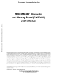
the maximum CPU operating frequency is limited by the available bandwidth of the CPU bus. The ARM9
overcomes this limitation by using a Harvard bus architecture, which has separate instruction and data busses as
shown below.
This change of structure is one of the key elements that helps the ARM9 reach much higher processing rates than
the earlier ARM CPUs. The number of instruction cycles required for load and store instructions is reduced
compared to an ARM7 processor so that an ARM9 CPU is around 30% faster than an ARM7 running at the same
clock frequency. Being able to efficiently access the memory system is only part of the story, if you can access
the memory quickly the CPU must be able to process instructions at a similar rate. The key to the increased CPU
performance is the CPU pipeline.
1.4 The Pipeline
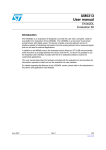
At the heart of the ARM9 CPU is the instruction pipeline. The pipeline is used to process instructions taken from
the program store. On the ARM7 a three-stage pipeline is used.
The ARM9 five-stage pipeline has independent fetch, decode, execute memory (read) and (memory) write
stages.
A three-stage pipeline is the simplest form of pipeline which has independent hardware units for fetch, decode
and execute. The ARM9 extends this pipeline with additional memory read and write stages. In the three-stage
ARM7 pipeline the memory and write functions are part of the execute stage. The ARM9 pipeline gives these
functions their own dedicated hardware as part of the extended pipeline. This means that in the ARM9, execution
of each instruction is split over more stages with the “execute” stage split into three simpler sub stages. Since
these stages each perform a small part of each instruction they can be run at a higher clock rate than the shorter
© Hitex (UK) Ltd.
Page 10
Chapter 1: The ARM9 CPU Core
ARM7 three-stage pipeline boosting the overall CPU performance. This is true for code which is executed as a
sequential series of instructions, the code will pass through the pipeline in a linear fashion maximising the effect of
the pipeline. However when the code branches the pipeline must be flushed of instructions and refilled. This
introduces a processing latency were the pipeline has to be refilled every time the CPU branches to a procedure
or interrupt. Clearly the longer the pipeline the longer the latency. Later on in this chapter we will see how the
ARM instruction set minimises these branching latencies and how ST have designed their microcontroller to
complement the CPU pipeline. The pipeline is automatically enabled within the CPU and is essentially transparent
to the programmer. However there are a couple of cases where the developer must be aware of possible pipeline
side effects which can effect operation of code running on the CPU. The first and most important case is the
possibility of data dependencies between instructions. In this case if we have two sequential instructions where
one instruction depends on the result of another as shown below:
ADD
OR
R0, R1,R2
R3, R0,R4
// R0 = R1+R2
// R3 = R0|R4
The result from the first instruction is not available until it has passed through each stage of the pipeline. However
the result is required by the second instruction part way through its journey down the pipeline. Since the first
instruction has not competed, this result is not available and the pipeline is stalled. In practice the ARM9 fivestage pipeline includes forwarding paths that make results immediately available between stages and removes
this problem except for a few cases. The instruction sequence shown below will cause a pipeline “interlock cycle”
which is a pipeline stall for one cycle:
LDR
ADD
R0,[PC,#20]
R1,R0,R2
// load a memory location into R0
// R1 = R0+R2
Since this sequence does not adversely affect the ARM7 three-stage pipeline it is often used in ARM7 code.
However it should be avoided in ARM9 code by “instruction scheduling” which is simply moving the LDR
instruction forward an instruction or two in order to prevent the risk of a stall being caused by a data dependency.
Since most applications will be written in the C language this is a function of the compiler.
The second case where a programmer can get some unexpected exposure to the pipeline is that the PC is
running eight bytes ahead of the current instruction being executed, so care must be taken when calculating
offsets used in PC relative addressing.
For example, the instruction:
0x4000 LDR PC,[PC,#4]
will load the contents of the address PC+4 into the PC. As the PC is running eight bytes ahead, then the contents
of address 0x400C will be loaded into the PC and not 0x4004 as you might expect on first inspection.
1.5 Registers
The ARM7 is a load-and-store architecture, so in order to perform any data processing instructions the data has
first to be moved from the memory store into a central set of registers, then the data processing instruction has to
be executed and then the data is stored back into memory.
The ARM7 CPU is a load-andstore architecture. All data
processing instructions may
only be carried out on a central
register file.
© Hitex (UK) Ltd.
Page 11
Chapter 1: The ARM9 CPU Core
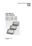
The central set of registers are a bank of 16 user registers R0 – R15. Each of these registers is 32 bits wide and
R0 – R12 are user registers (in that they do not have any specific other function.) The Registers R13 – R15 do
have special functions in the CPU. R13 is used as the stack pointer (SP). R14 is called the link register (LR).
When a call is made to a function, the return address is automatically stored in the link register and is immediately
available on return from the function. This allows quick entry and return into a ‘leaf’ function (a function that is not
going to call further functions). If the function is part of a branch (i.e. it is going to call other functions) then the link
register must be preserved on the stack (R13). Finally R15 is the program counter (PC). Interestingly, many
instructions can be performed on R13 - R15 as if they were standard user registers.
The central register file has 16 word wide registers plus
an additional CPU register called the Current Program
Status Register. R0 – R12 are user registers. R13 – R15
have special functions.
1.5.1
Current Program Status Register
In addition to the register bank there is an additional 32-bit wide register called the ‘current program status
register’ (CPSR). The CPSR contains a number of flags which report and control the operation of the ARM7 CPU.
The Current Program Status Register contains condition code flags which indicate the result of
data processing operations and User flags which set the operating mode and enable interrupts.
The T bit is for reference only.
The top four bits of the CPSR contain the condition codes which are set by the CPU. The condition codes report
the result status of a data processing operation. From the condition codes you can tell if a data processing
instruction generated a negative, zero, carry or overflow result. The fifth bit is the Q flag which is used by the
dedicated DSP instructions and is called the saturation flag. This flag is set when a DSP instruction causes an
overflow or saturation during a data processing instruction. The Q flag is also unique among the flags in that it is
a sticky bit. Once it is set by an instruction result it will stay set until it is cleared by the application code.
© Hitex (UK) Ltd.
Page 12
Chapter 1: The ARM9 CPU Core
The lowest eight bits in the CPSR contain flags which may be set or cleared by the application code. Bits 7 and 8
are the I and F bits. These bits are used to enable and disable the two interrupt sources which are external to the
ARM7 CPU. All of the STR9 peripherals are connected to these two interrupt lines as we shall see later. You
should be careful when programming these two bits, because in order to disable either interrupt source the bit
must be set to ‘1’, not ‘0’ as you might expect. Bit 5 is the THUMB bit.
The ARM9 CPU is capable of executing two instruction sets: the ARM instruction set which is 32 bits wide and the
THUMB instruction set which is 16 bits wide. Consequently the T bit reports which instruction set is being
executed. Your code should not try to set or clear this bit to switch between instruction sets. We will see the
correct entry mechanism a bit later. The last five bits are the mode bits. The ARM9 has seven different operating
modes. Your application code will normally run in the User Mode with access to the register bank R0 – R15 and
the CPSR as already discussed. However in response to an exception such as an interrupt, memory error or
software interrupt instruction, the processor will change modes. When this happens the registers R0 – R12 and
R15 remain the same, but R13 (LR ) and R14 (SP) are replaced by a new pair of registers unique to that mode.
This means that each mode has its own stack and link register. In addition, the fast interrupt mode (FIQ) has
duplicate registers for R7 – R12. This means that you can make a fast entry into an FIQ interrupt without the need
to preserve registers onto the stack.
Each of the modes except User Mode has an additional register called the “saved program status register”. If your
application is running in User Mode when an exception occurs, the mode will change and the current contents of
the CPSR will be saved into the SPSR. The exception code will run and on return from the exception the context
of the CPSR will be restored from the SPSR allowing the application code to resume execution. The operating
modes are listed below.
The ARM7 CPU has six
operating modes which are
used to process exceptions.
The shaded registers are
banked
memory
that
is
“switched
in”
when
the
operating mode changes. The
SPSR register is used to save a
copy of the CPSR when the
switch occurs.
© Hitex (UK) Ltd.
Page 13
Chapter 1: The ARM9 CPU Core
1.6 Exception Modes
When an exception occurs, the CPU will change modes and the PC will be forced to an exception vector. The
vector table starts from address zero with the reset vector and then has an exception vector every four bytes.
Each operating mode has an
associated interrupt vector. When
the processor changes mode the
PC will jump to the associated
vector.
NB: there is a missing vector at
0x00000014.
NB: There is a gap in the vector table because there is a missing vector at 0x00000014. This location was used
on an earlier ARM architecture and has been preserved on ARM7 to ensure software compatibility between
different ARM architectures.
Each of the exception sources has a fixed priority. The
on-chip peripherals are served by FIQ and IRQ
interrupts. Each peripheral’s priority may be assigned
within these groups.
If multiple exceptions occur then there is a fixed priority. When an exception occurs, for example an IRQ
exception, the following actions are taken. First the address of the next instruction to be executed (PC + 4) is
saved into the link register. Then the CPSR is copied into the SPSR of the exception mode that is about to be
entered (i.e. SPSR_irq). The PC is then filled with the address of the exception mode interrupt vector. In the case
of the IRQ mode this is 0x00000018. At the same time the mode is changed to IRQ mode, which causes R13 and
R14 to be replaced by the IRQ R13 and R14 registers.
© Hitex (UK) Ltd.
Page 14
Chapter 1: The ARM9 CPU Core
On entry to the IRQ mode, the I bit in the CPSR is set, causing the IRQ interrupt line to be disabled. If you need to
have nested IRQ interrupts, your code must manually re-enable the IRQ interrupt and push the link register onto
the stack in order to preserve the original return address. From the exception interrupt vector your code will jump
to the exception ISR. The first thing your code must do is to preserve any of the registers R0-R12 that the ISR will
use by pushing them onto the IRQ stack. Once this is done you can begin processing the exception.
When an exception occurs the CPU will change
modes and jump to the associated interrupt
vector.
Once your code has finished processing the exception it must return back to the User Mode and continue where it
left off. However the ARM instruction set does not contain a “return” or “return from interrupt” instruction so
manipulating the PC must be done by regular instructions. The situation is further complicated by there being a
number of different return cases. First of all, consider the SWI instruction. In this case the SWI instruction is
executed, the address of the next instruction to be executed is stored in the Link register and the exception is
processed. In order to return from the exception all that is necessary is to move the contents of the link register
into the PC and processing can continue. However in order to make the CPU switch modes back to User Mode, a
modified version of the move instruction is used and this is called MOVS (more about this later). Hence for a
software interrupt the return instruction is:
MOVS
R15,R14
; Move Link register into the PC and switch modes.
However, in the case of the FIQ and IRQ instructions, when an exception occurs the current instruction being
executed is discarded and the exception is entered. When the code returns from the exception the link register
contains the address of the discarded instruction plus four. In order to resume processing at the correct point we
need to roll back the value in the Link register by four. In this case we use the subtract instruction to deduct four
from the link register and store the results in the PC. As with the move instruction, there is a form of the subtract
instruction which will also restore the operating mode. For an IRQ, FIQ or Prog Abort, the return instruction is:
SUBS R15, R14,#4
In the case of a data abort instruction, the exception will occur one instruction after execution of the instruction
which caused the exception. In this case we will ideally enter the data abort ISR, sort out the problem with the
memory and return to reprocess the instruction that caused the exception. This means we have to roll back the
PC by two instructions, i.e. the discarded instruction and the instruction that caused the exception. In other words
subtract eight from the link register and store the result in the PC. For a data abort exception the return instruction
is:
SUBS R15, R14,#8
© Hitex (UK) Ltd.
Page 15
Chapter 1: The ARM9 CPU Core
Once the return instruction has been executed, the modified contents of the link register are moved into the PC,
the User Mode is restored and the SPSR is restored to the CPSR. Also, in the case of the FIQ or IRQ exceptions,
the relevant interrupt is enabled. This exits the privileged mode and returns to the user code ready to continue
processing.
At the end of the exception
the CPU returns to user
mode and the context is
restored by moving the
SPSR to the CPSR.
© Hitex (UK) Ltd.
Page 16
Chapter 1: The ARM9 CPU Core
1.7 ARM9 Instruction Set
Now that we have an idea of the ARM9 architecture, programmers’ model and operating modes, we need to take
a look at its instruction set (or rather sets.) Since all our programming examples are written in C, there is no need
to be an expert ARM9 assembly programmer. However an understanding of the underlying machine code is very
important in developing efficient programs. Before we start our overview of the ARM9 instructions it is important to
set out a few technicalities. The ARM9 CPU has two instruction sets: the ARM instruction set which has 32-bit
wide instructions and the THUMB instruction set which has 16-bit wide instructions. In the following section the
use of the word ARM means the 32-bit instruction set and ARM9 refers to the CPU.
The ARM9 is designed to operate as a big-endian or little-endian processor. That is, the MSB is located at the
high order bit or the low order bit. You may be pleased to hear that the STR9 family fixes the endianess of the
processor as little-endian (i.e. MSB at highest bit address), which
does make it a lot easier to work with. However the ARM9 compiler
you are working with will be able to compile code as little-endian or
big-endian. You must be sure you have it set correctly or the
compiled code will be back to front.
The ARM7 CPU is designed to support code
compiler in big-endian or little-endian format. The
ST silicon is fixed as little-endian.
One of the most interesting features of the ARM instruction set is that every instruction may be conditionally
executed. In a more traditional microcontroller the only conditional instructions are conditional branches and
maybe a few others like bit test and set. However in the ARM instruction set the top four bits of the operand are
compared to the condition codes in the CPSR. If they do not match, then the instruction is not executed and
passes through the pipeline as a NOP (no operation).
Every ARM (32-bit) instruction is conditionally executed. The top
four bits are ANDed with the CPSR condition codes. If they do
not match the instruction is executed as a NOP.
So it is possible to perform a data processing instruction which affects the condition codes in the CPSR. Then,
depending on this result, the following instructions may or may not be carried out. The basic Assembler
instructions such as MOV or ADD can be prefixed with sixteen conditional mnemonics, which define the condition
code states to be tested for.
Each ARM (32- bit) instruction can
be prefixed by one of 16 condition
codes. Hence each instruction has
16 different variants.
© Hitex (UK) Ltd.
Page 17
Chapter 1: The ARM9 CPU Core
So for example:
EQMOV R1, #0x00800000
will only move 0x00800000 into the R1 if the last result of the last data processing instruction was equal and
consequently set the Z flag in the CPSR. The aim of this conditional execution of instructions is to keep a smooth
flow of instructions through the pipeline. Every time there is a branch or jump, the pipeline is flushed and must be
refilled and this causes a dip in overall performance. In practice, there is a break-even point between effectively
forcing NOP instructions through the pipeline and a traditional conditional branch and refill of the pipeline. This
break-even point is three instructions, so a small branch such as:
if( x<100)
{
x++;
}
would be most efficient when coded using conditional execution of ARM instructions.
The main instruction groups of the ARM instruction set fall into six different categories, Branching, Data
Processing, Data Transfer, Block Transfer, Multiply and Software Interrupt.
1.7.1 Branching
The basic branch instruction (as its name implies) allows a jump forwards or backwards of up to 32 MB. A
modified version of the branch instruction, the branch link, allows the same jump but stores the current PC
address plus four bytes in the link register.
The branch instruction has several forms. The
branch instruction will jump you to a destination
address. The branch link instruction jumps to the
destination and stores a return address in R14.
So the branch link instruction is used as a call to a function storing the return address in the link register. The
branch instruction can be used to branch on the contents of the link register to make the return at the end of the
function. By using the condition codes we can perform conditional branching and conditional calling of functions.
The branch instructions have two other variants called “branch exchange” and “branch link exchange”. These two
instructions perform the same branch operation, but also swap instruction operation from ARM to THUMB and
vice versa.
© Hitex (UK) Ltd.
Page 18
Chapter 1: The ARM9 CPU Core
The branch exchange and branch link exchange
instructions perform the same jumps as branch and
branch link but also swap instruction sets from ARM to
THUMB and vice versa.
This is the only method you should use to swap instruction sets, as directly manipulating the T bit in the CPSR
can lead to unpredictable results.
1.7.2 Data Processing Instructions
The general form for all data processing instructions is shown below. Each instruction has a result register and
two operands. The first operand must be a register, but the second can be a register or an immediate value.
The general structure of the data
processing instructions allows for
conditional execution, a logical shift of
up to 32 bits and the data operation all
in the one cycle.
In addition, the ARM9 core contains a barrel shifter which allows the second operand to be shifted by a full 32-bits
within the instruction cycle. The “S” bit is used to control the condition codes. If it is set, the condition codes are
modified depending on the result of the instruction. If it is clear, no update is made. If, however, the PC (R15) is
specified as the result register and the S flag is set, this will cause the SPSR of the current mode to be copied to
the CPSR. This is used at the end of an exception to restore the PC and switch back to the original mode. Do not
try this when you are in the User Mode as there is no SPSR and the result would be unpredictable.
Mnemonic
Meaning
AND
EOR
SUB
RSB
ADD
ADC
SBC
RSC
TST
TEQ
CMP
CMN
ORR
Logical bitwise AND
Logical bitwise exclusive OR
Subtract
Reverse Subtract
Add
Add with carry
Subtract with carry
Reverse Subtract with carry
Test
Test Equivalence
Compare
Compare negated
Logical bitwise OR
© Hitex (UK) Ltd.
Page 19
Chapter 1: The ARM9 CPU Core
Mnemonic
Meaning
MOV
BIC
MVN
Move
Bit clear
Move negated
These features give us a rich set of data processing instructions which can be used to build very efficiently-coded
programs, or to give a compiler-designer nightmares. An example of a typical ARM instruction is shown below.
if(Z ==1)R1 = R2+(R3x4)
Can be compiled to:
EQADDS R1,R2,R3,LSL #2
1.7.2.1 Copying Registers
The next group of instructions are the data transfer instructions. The ARM9 CPU has load-and-store register
instructions that can move signed and unsigned Word, Half Word and Byte quantities to and from a selected
register.
Mnemonic
Meaning
LDR
LDRH
LDRSH
LDRB
LRDSB
Load
Load
Load
Load
Load
STR
STRH
STRSH
STRB
STRSB
Store
Store
Store
Store
Store
Word
Half Word
Signed Half Word
Byte
Signed Byte
Word
Half Word
Signed Half Word
Byte
Signed Half Word
Since the register set is fully orthogonal it is possible to load a 32-bit value into the PC, forcing a program jump
anywhere within the processor address space. If the target address is beyond the range of a branch instruction, a
stored constant can be loaded into the PC.
1.7.2.2 Copying Multiple Registers
In addition to load and storing single register values, the ARM has instructions to load and store multiple registers.
So with a single instruction, the whole register bank or a selected subset can be copied to memory and restored
with a second instruction:
The load and store multiple instructions allow
you to save or restore the entire register file or
any subset of registers in the one instruction.
© Hitex (UK) Ltd.
Page 20
Chapter 1: The ARM9 CPU Core
1.8 Swap Instruction
The ARM instruction set also provides support for real time semaphores with a swap instruction. The swap
instruction exchanges a word between registers and memory as one atomic instruction. This prevents crucial data
exchanges from being interrupted by an exception. This instruction is not reachable from the C language and is
supported by intrinsic functions within the compiler library.
The swap instruction allows you to exchange the
contents of two registers. This takes two cycles
but is treated as a single atomic instruction so the
exchange cannot be corrupted by an interrupt.
1.9 Modifying The Status Registers
As noted in the ARM9 architecture section, the CPSR and the SPSR are CPU registers, but are not part of the
main register bank. Only two ARM instructions can operate on these registers directly. The MSR and MRS
instructions support moving the contents of the CPSR or SPSR to and from a selected register. For example, in
order to disable the IRQ interrupts the contents of the CPSR must be moved to a register, the “I” bit must be set
by ANDing the contents with 0x00000080 to disable the interrupt and then the CPSR must be reprogrammed with
the new value.
The CPSR and SPSR are not memory-mapped or
part of the central register file. The only instructions
which operate on them are the MSR and MRS
instructions. These instructions are disabled when
the CPU is in USER mode.
The MSR and MRS instructions will work in all processor modes except the User Mode. So it is only possible to
change the operating mode of the process, or to enable or disable interrupts, from a privileged mode. Once you
have entered the User Mode you cannot leave it, except through an exception, reset, FIQ, IRQ or SWI instruction.
© Hitex (UK) Ltd.
Page 21
Chapter 1: The ARM9 CPU Core
1.10 Software Interrupt
The Software Interrupt Instruction generates an exception on execution, forces the processor into Supervisor
mode and jumps the PC to 0x00000008. As with all other ARM instructions, the SWI instruction contains the
condition execution codes in the top four bits followed by the op code. The remainder of the instruction is empty.
However, it is possible to encode a number into these unused bits. On entering the software interrupt, the
software interrupt code can examine these bits and decide which code to run. So it is possible to use the SWI
instruction to make calls into the protected mode, in order to run privileged code or make operating system calls.
The Software Interrupt Instruction forces the CPU into SUPERVISOR mode and jumps the PC to
the SWI vector. Bits 0-23 are unused and user defined numbers can be encoded into this space.
The Assembler Instruction:
SWI #3
will encode the value 3 into the unused bits of the SWI instruction. In the SWI ISR routine we can examine the
SWI instruction with the following code pseudo code:
switch( *(R14-4) & 0x00FFFFFF) //
//
{
//
//
case ( SWI-1)
……
roll back the address stored in link reg
by 4 bytes
Mask off the top 8 bits and switch
on result
Depending on your compiler, you may need to implement this yourself, or it may be done for you in the compiler
implementation.
1.11 MAC Unit
In addition to the barrel shifter, the ARM9 has an enhanced Multiply Accumulate Unit (MAC). The MAC supports
same integer and long integer multiplication that are available the ARM9. The integer multiplication instructions
support multiplication of two 32-bit registers and place the result in a third 32-bit register (modulo32). A multiplyaccumulate instruction will take the same product and add it to a running total. Long integer multiplication allows
two 32-bit quantities to be multiplied together and the 64-bit result is placed in two registers. Similarly a long
multiply and accumulate is also available.
Instruction
MUL
MULA
UMULL
UMLAL
SMULL
SMLAL
Operation
32x32 = 32
32x32+32
32x32 = 64
32x32+64
32x32 = 64
32x32+64
= 32
= 64
= 64
Purpose
Multiply
MAC
Unsigned multiply
Unsigned MAC
Signed multiply
Signed MAC
In addition to the 32 bit multiplies the ARM9 has some additional maths instructions designed to support DSP type
applications and fast multiplies.
© Hitex (UK) Ltd.
Page 22
Chapter 1: The ARM9 CPU Core
1.12 DSP Extensions
The ARM9 instruction set includes an additional group of instructions aimed at increasing the efficency of the
ARM CPUs when running complex mathematical algorithms, which are required in advanced control applications
such as motor drives or consumer electronics such as MP3 players. Like all the other ARM instructions the DSP
instructions can operate on any register in the CPU register file and with the exception of the saturated
instructions they are also conditionally executable. The first group of instructions are an additional set of single
cycle multiply instructions supported by the enhanced MAC unit. These include a single cycle 16 x16 multiply and
a 32 x 16 multiply.
Instruction
Operation
SMLAxy
SMLAWy
SMLALxy
SMULxy
SMULWy
16x16 +32
32x16+32
16x16+64
16x16
16x32
Purpose
=
=
=
=
=
32
32
64
32
32
Signed
Signed
Signed
Signed
Signed
MAC
MAC wide
MAC long
multiply
multiply long
The 16x16 multiply instructions operate on the upper and lower halves of a 32 bit wide register. So if you arrange
your 16 bit integers in adjoining half words a single load can be used to move both operands into the register file.
The next group of DSP instructions implement saturated addition and subtraction instructions.
1.13 THUMB Instruction Set
Although the ARM9 is a 32-bit processor, it has a second 16-bit instruction set called THUMB. The THUMB
instruction set is really a compressed form of the ARM instruction set.
The THUMB instruction set is
essential for archiving the
necessary code density to
make small single chip ARM7
micros usable.
This allows instructions to be stored in a 16-bit format, expanded into ARM instructions and then executed.
Although the THUMB instructions will result in lower code performance compared to ARM instructions, they will
achieve a much higher code density. So, in order to build a reasonably-sized application that will fit on a small
single chip microcontroller, it is vital to compile your code as a mixture of ARM and THUMB functions. This
process is called interworking and is easily supported on all ARM compilers. By compiling code in the THUMB
instruction set you can get a space saving of 30%, while the same code compiled as ARM code will run 40%
faster.
The THUMB instruction set is much more like a traditional microcontroller instruction set. Unlike the ARM
instructions, THUMB instructions are not conditionally executed (except for conditional branches). The data
processing instructions have a two-address format, where the destination register is one of the source registers:
ARM Instruction
ADD R0, R0,R1
© Hitex (UK) Ltd.
THUMB Instruction
ADD R0,R1
Page 23
R0 = R0+R1
Chapter 1: The ARM9 CPU Core
The THUMB instruction set does not have full access to all registers in the register file. All data processing
instructions have access to R0 –R7 (these are called the “low registers”).
In the THUMB programmer’s model all
instructions have access to R0-R7. Only a
few instructions may access R8-R12.
However access to R8-R12 (the “high registers”) is restricted to a few instructions:
MOV, ADD, CMP
The THUMB instruction set does not contain MSR and MRS instructions, so you can only indirectly affect the
CPSR and SPSR. If you need to modify any user bits in the CPSR you must change to ARM mode. You can
change modes by using the BX and BLX instructions. Also, when you come out of RESET, or enter an exception
mode, you will automatically change to ARM mode.
After Reset the ARM9 will execute ARM (32-bit)
instructions.
The instruction set can be
exchanged at any time using BX or BLX. If an
exception occurs the execution is automatically
forced to ARM (32- bit).
The THUMB instruction set has the more traditional PUSH and POP instructions for stack manipulation. They
implement a fully descending stack, hardwired to R13.
The THUMB instruction set has dedicated
PUSH and POP instructions which implement
a descending stack using R13 as a stack
pointer.
© Hitex (UK) Ltd.
Page 24
Chapter 1: The ARM9 CPU Core
Finally, the THUMB instruction set does contain a SWI instruction which works in the same way as in the ARM
instruction set, but it only contains 8 unused bits, to give a maximum of 255 SWI calls.
1.14 Summary
At the end of this chapter you should have a basic understanding of the ARM9 CPU. Please see the bibliography
for a list of books that address the ARM9 in more detail. Also included on the CD is a copy of the ARM9 user
manual.
© Hitex (UK) Ltd.
Page 25
Chapter 1: The ARM9 CPU Core
© Hitex (UK) Ltd.
Page 26
Chapter 2: Software Development
© Hitex (UK) Ltd.
Page 27
Chapter 2: Software Development
2 Chapter 2: Software Development
2.1 Outline
Having read Chapter One, you should now have an understanding of the ARM9 CPU. In this chapter we will look
at how to write and debug C code for the ARM9. The example programs in this chapter will concentrate on
demonstrating how to use the unique features of the ARM9 discussed in the first chapter.
Since the ARM9 is rapidly becoming an industry standard CPU for general purpose microcontrollers, this will
allow you to develop code on the STR9 and a number of other devices.
© Hitex (UK) Ltd.
Page 28
Chapter 2: Software Development
2.2 The Development Tools
The CD that comes with the STR9 starter kit includes an evaluation toolchain for the STR9. This is complete with
a number of example programs demonstrating all the major features of the STR9 microcontroller. By reading
through the book and running the exercises, you will be able to very quickly familiarise yourself with the essential
features of the STR9. All of these exercises are detailed in Chapter 5. Once you have read the theory section and
reached an exercise, turn to the Exercise Worksheet in Chapter 5 and follow the instructions. The exercises
expand on the basic theory and give you a practical handle on the operation of the STR9.
Exercise 1: Installing The Software
Turn to the tutorial chapter and follow the instructions in Exercise 1 which describe setting up the
software and hardware toolchain that we will use for the practical examples in this book
2.2.1 HiTOP Debugger & IDE
HiTOP is the front end for all Hitex debuggers and in-circuit emulators. In the case of the STR9, HiTOP connects
to the TantinoARM 7-9 JTAG debugger. The JTAG allows HiTOP to download code into the STR9 FLASH or
RAM and then debug the code as it runs on the microcontroller. In addition to its debugging features, HiTOP
includes a programmers’ editor and support for various compiler tools and make utilities that allow you to maintain
existing STR9 programs.
2.2.2 Which Compiler?
The HiTOP development environment can be used with several different compiler tools. These include compilers
from ARM, Keil, Greenhills, Tasking and IAR. There is also a port of the GNU GCC compiler available for the
ARM series of CPUs. GCC has the advantage of being a free compiler which will compile C and C++ code for all
of the ARM series of CPUs.
The commercial compilers are streets ahead of the GNU tools in terms of code density and speed of execution.
Increasingly, the commercial compilers include direct support for ARM-based microcontrollers in the form of
debuggers with support for the STR9 and dedicated compiler switches. The reasons to use each of the given
compilers can be summed up as follows: if you want the fastest code and standard tools with proper technical
support use a commercial tool like the Keil RealView ARM compiler. If you have no budget, a simple project or
have considerable previous experience of it, use the GNU. Delivered with the STR9 starter kit is a free
installation of the GNU compiler, which integrates with the HiTOP debugger IDE so that you can compile simple
programs. The examples given here use the GNU compiler.
2.2.3 DA-C
Also included with the development toolchain is a second editor called Development Assistant for C. This is an
advanced editor specifically targeted at embedded systems developers. As well as having all the features you
would expect in a programmer’s editor, DA-C includes a number of advanced features that help you to produce
high quality and well-documented C source code. DA-C includes a static checker that will analyse your code for
common programming errors, generate flow charts and calling hierarchies. DA-C also includes a code browser,
so you can easily navigate your code and a metrics module so the source code may be analysed using quality
standard measures.
2.2.4 TESSY
The final item of software included on the CD is a software testing tool suite called TESSY. The TESSY toolset
automates the functional testing of embedded microcontrollers and their target hardware. In many industries
(especially aerospace and medical), validation of microcontroller firmware is a lengthy and important process.
TESSY is especially suitable for testing small footprint microcontrollers which only have small amounts of on-chip
© Hitex (UK) Ltd.
Page 29
Chapter 2: Software Development
memory. Rather than build a test harness that is downloaded into the target memory of the device under test,
TESSY makes no changes to the code under test but builds its test harness in the HiScript language built into the
debugger. This way the target application can be fully exercised without the loss of any on-chip resources.
2.3 Startup Code
In our example project we have a number of source files. In practice the .c files are your source code, but the file
startup912.s is an Assembler module provided by Hitex to support the STR9 microcontroller. As its name implies,
the startup code is located to run from the reset vector. It provides the exception vector table, as well as initialising
the stack pointer for the different operating modes. It also initialises some of the on- chip system peripherals and
the on-chip RAM before it jumps to the main function in your C code. The startup code will vary, depending on
which ARM9 device you are using and which compiler you are using, so for your own project it is important to
make sure you are using the correct file.
First of all the startup code provides the exception vector table as shown below:
#*************************************************************************
# Exception Vectors
#*************************************************************************
Vectors:
LDR
PC, Reset_Addr
/* Located at address = 0x0000 */
LDR
PC, Undef_Addr
/* 0x0004 */
LDR
PC, SWI_Addr
/* 0x0008 */
LDR
PC, PAbt_Addr
/* 0x000C */
LDR
PC, DAbt_Addr
/* 0x0010 */
NOP
/* 0x0014 Reserved Vector */
LDR
PC, [PC, #-0xFF0]
/* 0x0018 wraps around address space to */
/* 0xFFFFFF030. Vector from VicVECAddr */
LDR
PC, FIQ_Addr
/* 0x001C FIQ has no VIC vector slot!
*/
#*************************************************************************
# Interrupt Vectors
#*************************************************************************
Reset_Addr:
Undef_Addr:
SWI_Addr:
PAbt_Addr:
DAbt_Addr:
IRQ_Addr:
FIQ_Addr:
.word
.word
.word
.word
.word
.word
.word
.word
Hard_Reset
Undef_Handler
SWI_Handler
PAbt_Handler
DAbt_Handler
0
IRQ_Handler
FIQ_Handler
/* CPU reset vector and entry point */
/* Reserved Address */
/* Does not get used due to */
/* "LDR PC, [PC, #-0xFF0]" above */
The vector table is located at 0x00000000 and provides a jump to interrupt service routines (ISR) on each vector.
If your code is located to run from 0x00000000 then the vector table can be made from a series of branch
instructions. You must remember to pad the unused interrupt vector with a NOP, also note the different type of
Assembler instruction on the IRQ interrupt vector above. This will be discussed in Chapter 3 when we look at the
interrupt structure in more detail.
Using the Branch instruction means that the entry point to our application software and the interrupt routines must
be located within the first 32Mb on the STR9 memory map since this is the address range of the branch
instruction. A more generic way to handle the vector table is to use the LDR instruction to load a 32 bit constant
into the PC. This method uses more memory, but allows you to locate your code anywhere in the 4Gb address
range of the ARM9.
© Hitex (UK) Ltd.
Page 30
Chapter 2: Software Development
Vectors:
LDR
LDR
LDR
LDR
LDR
NOP
LDR
LDR
LDR
PC,Reset_Addr
PC,Undef_Addr
PC,SWI_Addr
PC,PAbt_Addr
PC,DAbt_Addr
/* Reserved Vector */
PC,IRQ_Addr
PC,[PC, #-0x0808]
PC,FIQ_Addr
Reset_Addr:
Undef_Addr:
SWI_Addr:
PAbt_Addr:
DD
DD
DD
DD
Reset_Handler
Undef_Handler
SWI_Handler
PAbt_Handler
DAbt_Addr
DD
DD
DD
DD
DAbt_Handler
0
/* Reserved Address */
IRQ_Handler
FIQ_Handler
IRQ_Addr:
FIQ_Addr:
The vector table and the constants table take up the first 64 bytes of memory. On the STR9 the memory at
0x00000000 may be mapped from a number of different sources either on-chip FLASH, RAM or external FLASH
memory. (This is discussed more fully later on.) Whichever method you use, you are responsible for managing
the vector table in the startup code, as it is not done automatically by the compiler.
The startup code is also responsible for configuring the stack pointers for each of the operating modes.
The six on-chip stack pointers (R13)
are initialised at the top of on-chip
memory. Care must be taken to
allocate enough memory for the
maximum size of each stack.
Since each operating mode has a unique R13, there are effectively six stacks in the ARM9. The strategy used by
the compiler is to locate user variables from the start of the on-chip RAM and grow upwards. The stacks are
located at the top of memory and grow downwards. The startup code enters each different mode of the ARM9
and loads each R13 with the starting address of the stack.
The User Stack is the most important and must be located at the lowest address. The Heap is placed at the
bottom of the User Stack area and this needs to be able to make use of the memory between the User Stack and
the uninitialised data area (BSS).
© Hitex (UK) Ltd.
Page 31
Chapter 2: Software Development
Like the vector table, you are responsible for configuring the stack size. This can be done by editing the startup
code directly.
#*************************************************************************
# Stack definitions
#*************************************************************************
.equ
.equ
.equ
.equ
.equ
.equ
.equ
UND_Stack_Size,
1*4
SVC_Stack_Size,
32*4
ABT_Stack_Size,
1*4
FIQ_Stack_Size,
32*4
IRQ_Stack_Size,
64*4
USR_Stack_Size,
128*4
Top_Stack, RAM_Base + RAM_Size
Exercise 2: Configuring the ARM9 Startup code
This exercise focuses on the startup code. The CPU stacks are set up and checked in the
debugger. The other critical areas of the startup code are also examined.
© Hitex (UK) Ltd.
Page 32
Chapter 2: Software Development
2.4 The ARM Procedure Call Standard (APCS)
The ARM procedure calling standard defines how the ARM9 register file is used by the compiler during runtime. In
theory, the APCS allows code built in different toolsets to work together, so that you can take a library compiled
by the ARM compiler and use it with the GCC toolset.
The ARM procedure call standard defines how the
user CPU registers should be used by compilers.
Adhering to this standard allows interworking
between different manufacturers’ tools
The APCS splits the register file into a number of regions. R0 to R3 are used for parameter passing between
functions. If you need to pass more than 16 bytes then spilled parameters are passed via the stack. Local
variables are allocated R4 – R11 and R12 is reserved as a memory location for the intra-call veneer code. As you
select more options for the generated code such as re-entrancy and stack-checking, the compiler adds additional
Assembler code to support these features. These Assembler veneers effectively add overhead to your code, so it
is important to only enable features which you intend to use. The APCS also defines a stack frame which
preserves the context of the CPU registers and also contains a pointer to the previous stack frame.
This is a very useful software debug task within an operating system such as Linux, but it isn’t that useful for a
JTAG debugger. The ARM procedure calling standard has a big impact on the speed of execution and stack size
for the final application. Consequently for a small embedded microcontroller like the STR9 it is best to stop the
compiler from using this standard. The compiler switch used to enable the APCS standard is:
-mapcs-frame or -apcs
And to disable it
-mno-apcs-frame
By default StartEasy generates a project which disables the use of the APCS.
© Hitex (UK) Ltd.
Page 33
Chapter 2: Software Development
2.5 Interworking ARM and THUMB
One of the most important features of the ARM9 CPU is its ability to run 16 bit THUMB code and 32 bit ARM
code. In order to get a reasonably complex application to fit into the on-chip FLASH memory, it is very important
to interwork these two instruction sets so that most of the application code is encoded in the THUMB instruction
set and is effectively compressed to take minimal space in the on-chip FLASH memory. Any time-critical routines
where the full processing power of the ARM 7 is required need to be encoded in the ARM 32 bit instruction set.
When generating the code, the compiler must be enabled to allow interworking. This is achieved with the following
switch:
-mTHUMB-interwork
The GCC compiler is designed to compile a given C module in either the THUMB or ARM instruction set.
Therefore you must lay out your source code so that each module only contains functions that will be encoded as
ARM or THUMB functions. By default the compiler will encode all source code in the ARM instruction set. To force
a module to be encoded in the THUMB instruction set, use the following directive when you compile the code:
-mTHUMB
This option can be added to a given module within the HiTOP IDE.
The linker can then take both ARM and THUMB object files and produce a final executable that interworks both
instruction sets.
Exercise 3: Interworking
The next exercise demonstrates setting up a project that interworks ARM and THUMB
code.
2.6 STDIO Libraries
The “Hello World” example in Exercise 1 uses a simple print_f routine which will print simple strings to a terminal.
The GCC compiler has a full ANSI C library which includes the full high-level formatted I/O functions such as
scanf and printf. These functions call low-level driver functions that can be modified to the I/O stream to a given
peripheral. These functions are stored in a file called syscalls.c. If you intend to use the STDIO library you should
add this module to your project and then tailor the driver functions to match your I/O device.
Bear in mind that the high level STDIO functions are quite bulky and should only be used if your application is
very I/O driven.
2.7 Accessing Peripherals
Once we have built some code and got it running on an STR9 device, it will at some point be necessary to access
the special function registers (SFR) in the peripherals. As all the peripherals are memory-mapped, they can be
accessed as normal memory locations. Each SFR location can be accessed by ‘hardwiring’ a volatile pointer to its
memory location as shown below.
#define SFR
(*((volatile unsigned long *) 0xFFFFF000))
StartEasy generates an include file which defines all the SFRs in the different STR9 variants. The include file is
added to your skeleton project. This allows you to directly access any STR9 peripheral SFR directly using the
data book naming convention.
© Hitex (UK) Ltd.
Page 34
Chapter 2: Software Development
2.8 Interrupt Service Routines
In addition to accessing the on-chip peripherals, your C code will have to service interrupt requests. It is possible
to convert a standard function into an ISR as shown below:
void fiqint (void)
{
IOSET1
EXTINT
__attribute__ ((interrupt("FIQ")));
= 0x00FF0000;
= 0x00000002;
// Set the LED pins
// Clear the peripheral interrupt flag
}
The keyword __fiq defines the function as a fast interrupt request service routine and will use the correct return
mechanism. Other types of interrupt are supported by the keywords __IRQ, __SWI and _UNDEF.
As well as declaring a C function as an interrupt routine, you must link the interrupt vector to the function.
Vectors:
;
Reset_Addr:
Undef_Addr:
SWI_Addr:
PAbt_Addr:
DAbt_Addr:
IRQ_Addr:
FIQ_Addr:
LDR
LDR
LDR
LDR
LDR
NOP
LDR
LDR
LDR
PC,Reset_Addr
PC,Undef_Addr
PC,SWI_Addr
PC,PAbt_Addr
PC,DAbt_Addr
DD
DD
DD
DD
DD
DD
DD
DD
Reset_Handler
Undef_Handler?A
SWI_Handler?A
PAbt_Handler?A
DAbt_Handler?A
0
IRQ_Handler?A
FIQ_Handler?A
/* Reserved Vector */
PC,IRQ_Addr
PC,[PC, #-0x0FF0]
PC,FIQ_Addr
/* Vector from VicVectAddr */
/* Reserved Address */
The vector table is in two parts. First there is the physical vector table which has a load register instruction (LDR)
on each vector. This loads the contents of a 32-bit wide memory location into the PC, forcing a jump to any
location within the processor’s address space. These values are held in the second half of the vector table, or
constants table which follows immediately after the vector table. This means that the complete vector table takes
the first 64 bytes of memory. The startup code contains predefined names for the Interrupt Service Routines
(ISR). You can link your ISR functions to each interrupt vector by using the same name as your C function name.
The table below shows the constants table symbols and the corresponding C function prototypes that should be
used.
Exception Source
Undefined Instruction
Software Interrupt
Prefetch Abort
Data Abort
Fast Interrupt
Constant
Undef_Handler
SWI_Handler
PAbt_Handler
DAbt_Handler
FIQ_Handler
C Function Prototype
voidUndef_Handler(void) __attribute__ ((interrupt("undef”)));
void SWI_Handler(void) __attribute__ ((interrupt("swi”)));
void Pabt_Handler (void) __attribute__ ((interrupt("undef”)));
void Dabt_Handler (void) __attribute__ ((interrupt("undef”)));
void FIQ_Handler (void) __attribute__ ((interrupt("fiq”)));
As you can see from the table, there is no routine defined for the IRQ interrupt source. The IRQ exceptions are
special cases as we will see later. Only the IRQ and FIQ interrupt sources can be disabled. The protection
exceptions (Undefined Instruction, Prefetch Abort, and Data Abort) are always enabled. Consequently these
exceptions must always be trapped. As a minimum you should ensure that these interrupt sources are trapped in
a tight loop, as shown below.
Pabt_Handler:
© Hitex (UK) Ltd.
B
Pabt Handler
Page 35
;
Branch back to Pabt_Handler
Chapter 2: Software Development
If your code does encounter a memory error and ends up in one of these loops, you can examine the contents of
the Abort Link Register to determine the address+4 of the instruction which caused the error. The SPSR will
contain details of the operating mode which the CPU was in when the error occurred. From here you can
backtrack and also examine the contents of the stack immediately before the application program crashed. So the
CPU registers can produce some useful post mortem diagnostics if you know what you are looking for.
2.9 Software Interrupt
The Software Interrupt exception is a special case. As we have seen it is possible to encode an integer into the
unused portion of the SWI opcode.
#define SoftwareInterrupt2 asm ("swi #02")
Now when we execute this line of code, it will generate a software interrupt and switch the CPU into Supervisor
mode and vector the PC to the SWI interrupt vector, which will place the application into the SWI handler routine.
Once we enter this routine, we need to determine what code to run. It would be possible to read the contents of a
global variable and then use a switch statement to run a specific function depending on the contents of the global.
However, there is a more elegant method. In the GCC compiler there is a register keyword that allows us to
access a CPU register directly from C code. The declaration below declares a pointer to the link register.
register unsigned * link_ptr asm ("r14");
When we enter the software interrupt routine we can use this pointer to read the contents of the SWI instruction
which generated the interrupt. This allows us to read the integer number encoded into the SWI instruction. We
can then use this number to decide which function to run within the SWI handler.
temp = *(link_ptr-1) & 0x00FFFFFF;
The line above takes the contents of the link register and deducts one. Remember it is a word-wide pointer, so we
are in fact deducting four bytes. This rolls the contents of the link register back by four so it is pointing at the
address of the SWI instruction. Then the contents of the instruction with the top eight bits masked off (the
condition codes and the SWI op code) are copied into the temp variable.
The result is that the encoded integer (in this case 2) is now stored in the temp variable and we can use its
contents to decide which code to run. The SWI instruction is a convenient method of leaving User Mode to enter
the Supervisor mode and run some privileged code. The SWI calls can be used as part of a BIOS where all
access to the special function registers is made via software interrupt calls. This in effect partitions your
application code, so that all the hardware drivers run in Supervisor mode with their own stack and if necessary
their own memory space. You do not have to build your code this way, but if you want to make use of it, the
mechanism is there.
Exercise 4: Software Interrupt
The SWI support in the GCC compiler is demonstrated in this example. You can easily partition code
to run in either the User mode or in Supervisor mode.
© Hitex (UK) Ltd.
Page 36
Chapter 2: Software Development
2.10 In-Line Functions
It is also possible to increase the performance of your code by inlining your functions. The inline keyword can be
applied to any function as shown below:
inline void NoSubroutine (void)
{
…
}
When the inline keyword is used, the function will not be coded as a subroutine, but the function code will be
inserted at the point where the function is called, each time it is called. This removes the prologue and epilogue
code which is necessary for a subroutine, making its execution time faster. However, you are duplicating the
function every time it is called, so it is expensive in terms of your FLASH memory. The compiler will not inline
functions unless you have set the optimiser to its “O2” level.
2.10.1 Inline Assembler
The compiler also allows you to use ARM or THUMB Assembler instructions within a C file. This can be done as
shown below:
asm ( “mov r15,r2”
);
This can be useful if you need to use features that are not supported by the C language, for example the MRS
and MSR instructions as in these macros:
/* switch to SYS mode and enabled interrupts */
#define SWITCH_IRQ_TO_SYS asm(" msr CPSR_c,#0x1F \n stmfd sp!,{lr}" )
/* switch back to IRQ mode with IRQ disabled */
#define SWITCH_SYS_TO_IRQ asm (" ldmfd sp!,{lr} \n msr CPSR_c,#0x12|0x80")
2.11 Linker Script Files
Once you have written your source code and compiled it to object files, these files must be linked together to
make the final absolute file. The examples supplied contain linker files with the switches as well as a linker script
file (“EXAMPLE.LD”) that describes the target memory layout to the linker, so it knows how to build the final
application. The linker is invoked with the following switches:
ld ld_opt -o <project_name>.elf
where ld_opt is:
-T.\objects\<linker_file>.ld --cref -t -static -lgcc -lc -lm -nostartfiles Map=<project_name>.map
The linker script file is saved to your project directory and is given the extension .ld. It is important to understand
the structure of this file as you may need to modify it as your application code grows. The linker script file is a
structured text file with a number of sections that describe your project to the linker. First some search paths are
defined for the compiler libraries. These search paths must point to the libraries of the GCC installation you are
using:
SEARCH_DIR( "C:\Program Files\Hitex\GnuToolPackageARM\ARM-hitex-elf\lib\interwork"
)
SEARCH_DIR( "C:\Program Files\Hitex\GnuToolPackageARM\lib\gcc\ARM-hitexelf\4.0.0\interwork" )
The GCC compiler comes with several builds of the libraries. The version selected here supports ARM THUMB
interworking. The next section in the script file defines the list of input object files that make up the complete
project:
© Hitex (UK) Ltd.
Page 37
Chapter 2: Software Development
GROUP ( objects\startup.o
objects\main.o
objects\interrupt.o
objects\THUMB.o )
If you add any additional source modules to your project you must update this list in the .LD manually.
Following the group section is the target memory layout:
MEMORY
{
/* For STR9 FLASH execution */
IntCodeRAM
(rx) : ORIGIN = 0x00000000, LENGTH = 512K
IntDataRAM
(rw) : ORIGIN = 0x40000000, LENGTH = 96k
/* this is FLASH */
}
This section defines the size and location of the target memory. The description above describes the memory
configuration of an STR9 used as a single chip device with 512k of FLASH memory starting from address
0x0000000 and 96K of RAM starting from 0x40000000. The final user section describes how the application
code should be laid out within the target memory.
SECTIONS
{
.text
{
…
}
.data
{
…
}
}
The description of the application code is split into two basic sections, .text and .data. The .text section contains
the executable code and the code constants, basically anything that should be located in the FLASH memory.
The .data section allocates all of your volatile variables into the user RAM.
.text :
{
__code_start__ = .;
objects\startup.o (.text)
objects\*.o
(.text)
. = ALIGN(4);
__code_end__ = .;
*(.glue_7t) *(.glue_7)
/* Startup code */
} >IntCodeRAM = 0
The text section ensures that the startup code is assigned first, so it will be placed on the reset vector. Then the
remaining application code is assigned locations within the FLASH memory. The align command ensures that
each relocatable section is placed on the next available word boundary.
.data : AT (_etext)
{
/* used for initialized data */
__data_start__ = . ;
PROVIDE (__data_start__ = .) ;
*(.data)
SORT(CONSTRUCTORS)
__data_end__ = . ;
© Hitex (UK) Ltd.
Page 38
Chapter 2: Software Development
PROVIDE (__data_end__ = .) ;
} >IntDataRAM
. = ALIGN(4);
The .data section allocates the user variables into the on-chip RAM defined for the STR9.
Uninitialised data is placed in the BSS section:
.bss :
{
/* used for uninitialized data */
__bss_start = . ;
__bss_start__ = . ;
*(.bss)
. = ALIGN(4);
__bss_end__ = . ;
} >IntDataRAM
.bss2 :
{
/* used for uninitialized data */
__bss2_start = . ;
__bss2_start__ = . ;
*(COMMON)
. = ALIGN(4);
__bss2_end__ = . ;
} >IntDataRAM
Followed by the _end symbol that is used by the SYSCALLS module to manage the Heap area.
/* Required so that the heap can be initialised */
_end = .;
PROVIDE (end = .);
The stacks are generally placed at the top of the SRAM at 0x40018000 with the area between the base of the
User Stack and the .end symbol being used for the Heap.
2.12 C++ support
The GCC compiler is a C and C++ compiler, so while the examples in this book concentrate on using the C
language, it is also possible to build a program using the C++ language and make use of its richer programming
constructs. This is really outside the scope of this book, but an example is included in chapter 5 to get you started
if you want to use the C++ language.
© Hitex (UK) Ltd.
Page 39
Chapter 2: Software Development
2.13 Hardware Debugging Tools
ST Microelectronics have designed the STR9 to have the maximum on-chip debug support. There are several
levels of support. The simplest is a JTAG debug port. This port allows you to connect to the STR9 from the PC for
a debug session. The JTAG interface allows you to have basic run control of the chip. That is you can single step
lines of code, run halt and set breakpoints and also view variables and memory locations once the code is halted.
JTAG
connector
pinout
The JTAG connects to the target through a special debug port, which must be added to your target hardware. The
JTAG socket has a standard layout which is common to all ARM9-based devices. The JTAG is brought out of the
STR9 by six GPIO pins as secondary functions. This means that when you are using the JTAG these pins will be
unavailable for your application.
It is also worth noting that the even pins on the JTAG connector are mostly ground connections. This means that
if you accidentally plug your JTAG debugger in back to front, you will pull all of the signal lines to ground and
possibly damage the Tantino. For this reason the evaluation board is fitted with a polarised socket to prevent this
mishap. If you are designing your own hardware, it is recommended that you fit the same style of socket rather
than just a bare header.
© Hitex (UK) Ltd.
Page 40
Chapter 2: Software Development
2.14 Important
As mentioned above, the JTAG port is a simple serial debug connection to the ARM9 device. It is very important
to understand its behaviour during reset. If the ARM9 CPU is reset, all of the peripherals including the JTAG are
reset. When this happens the Tantino debugger loses control of the chip and has to re-establish control once the
STR9 device comes out of reset. This will take a finite number of clock cycles. While this is happening, any code
that is on the chip will be run as normal. Once the Tantino gets back control of the chip, it performs a soft reset by
forcing the PC back to address zero. However the on-chip peripherals are no longer in the reset condition, i.e.
peripherals will be initialised, interrupt enabled etc. You must bear this in mind if the application you are
developing could be adversely affected by this. A simple solution is to place a simple delay loop in the startup
code, or at the beginning of main(). After a reset occurs, the CPU will be trapped in this loop until the Tantino
regains control of the chip and none of the application code will have run, leaving the STR9 in its initialised
condition. A macro is included in the startup code to provide this delay:
.macro
StartupDelay delay_value
ldr
ldr
__StartDelay:
sub
cmp
bhi
R1, =\delay_value
R2, =0
R1, R1, #1
R1, R2
__StartDelay
.endm
This macro is called at the entry point to your application. It is only required for debugging and should be removed
on the released version of the code.
#*************************************************************************
# Reset Handler Entry Point
#*************************************************************************
Hard_Reset:
_app_entry:
StartupDelay 500000
Start_init_s:
2.15 Embedded Trace Module
In addition, ST has included the ARM embedded trace module. The embedded trace module provides much more
powerful debugging options and real time trace, code coverage, triggering and performance analysis toolsets. In
addition to more advanced debug tools, the ETM allows extensive code verification and software testing which is
just not possible with a simple JTAG interface. If you are designing for safety critical applications, this is a very
important consideration.
In addition to the JTAG port ST have included the ARM ETM
module for high end debugging tools.
© Hitex (UK) Ltd.
Page 41
Chapter 2: Software Development
The ETM debugging tools are more expensive than the JTAG tools. However if you are working on a safety
critical or similar high integrity application the real time trace, advanced triggering and code coverage features
allow you to validate your code to a high level of confidence. Even if you do not intend to use an ETM tool it is
worth tracking out the 9 (or 10 if the ETM_EXTRIG is used) signals required for the ETM socket on your
development hardware so if you do encounter a complex bug during development you at least have the chance of
using such a tool. Often such equipment is available for rental as well as purchase.
The pins to be used for ETM are shared with other peripheral IO functions so, at the design stage, a decision
must be made as to which pins are to be used. Fortunately each ETM function appears on multiple GPIO pins
and it is possible to take the ETM functions from several GPIO ports at the same time.
GPIO0
GPIO Mode
Alternate Out 3
Pin 0
ETM_PCK0
Pin 1
ETM_PCK1
Pin 2
Pin 3
GPIO1
GPIO2
GPIO3
X
Alternate Out 3
ETM_PCK0
X
ETM_PCK0
X
X
ETM_PCK1
X
ETM_PCK1
ETM_PCK2
X
X
ETM_PCK2
X
ETM_PCK2
ETM_PCK3
X
X
ETM_PCK3
X
ETM_PCK3
Pin 4
ETM_PSTAT0
X
X
ETM_PSTAT0
X
ETM_PSTAT0
Pin 5
ETM_PSTAT1
X
Pin 6
ETM_PSTAT2
X
Pin 7
ETM_TRSYNC ETM_EXTRIG
GPIO Mode
Alternate In 1
Pin 0
X
Pin 1
X
Pin 2
X
Pin 3
ETM_EXTRIG
ETM_EXTRIG
Alternate Out 3 Alternate Out 3
GPIO4
X
GPIO5
Alternate In 1
GPIO1
ETM_TRCLK
X
ETM_TRCLK
GPIO5
GPIO6
Alternate Out 2
Alternate In 1
ETM_TRCLK
ETM_PSTAT1
X
ETM_PSTAT1
ETM_PSTAT2
X
ETM_PSTAT2
ETM_TRSYNC
X
ETM_TRSYNC
GPIO6
GPIO7
GPIO7
Alternate Out 3 Alternate In 1 Alternate Out 3
X
X
X
ETM_PCK0
X
X
X
X
ETM_PCK1
X
X
X
X
ETM_PCK2
ETM_PCK3
X
X
X
X
Pin 4
X
X
X
X
X
X
Pin 5
X
X
X
X
ETM_EXTRIG
X
Pin 6
X
X
X
X
X
Pin 7
X
X
X
X
ETM_TRCLK
ETM_EXTRIG
X
The above table shows ETM-capable pins. The ETM alternate function is selected via the SCU_GPIOOUT and
SCU_GPIOIN registers as with any normal peripheral function. However some care needs to be taken when
choosing the pins due to the very high frequency of the ETM signals. Therefore it is best to take the complete
ETM_PCK0-3 and ETM_PSTAT0-2 signal set from one GPIO port, with the ETM_TRCLK from another port as
physically close by as possible.
2.16 Summary
By the end of this section you should be able to set up a project with HiTOP and GNU-C, select the compiler
options and the variant you want to use, configure the startup code, be able to interwork the ARM and THUMB
instruction sets, access the STR9 peripherals and write C functions to handle exceptions.
With this grounding we can now have a look at the STR9 system peripherals.
© Hitex (UK) Ltd.
Page 42
Chapter 3: System Peripherals
© Hitex (UK) Ltd.
Page 43
Chapter 3: System Peripherals
3 Chapter 3: System Peripherals
3.1 Outline
Now that we have some familiarity with the ARM9 core and the necessary development tools we can begin to
look at the STR9 device itself. In this section we will concentrate on the system peripherals, that is to say the
features which are used to control the performance and functional features of the device. This includes the onchip FLASH and SRAM memory, clock and power control subsystem and the on-chip DMA control units. Finally
we will take a look at the STR9 interrupt structure and the advanced support provided by ST to supplement the
two CPU interrupt lines IRQ and FIQ. This is a key chapter in understanding how ST have integrated the ARM9
CPU into a standard microcontroller architecture.
© Hitex (UK) Ltd.
Page 44
Chapter 3: System Peripherals
3.2 Bus Structure
To the programmer the memory of all STR9 devices is one contiguous 4 gigabyte 32-bit wide address range.
However the device itself is made up of a number of buses. The ARM9 core is connected to the Advanced High
Performance Bus (AHB) which is a bus structure defined by ARM. As its name implies, this is a high speed bus
running at the same frequency as the ARM9 CPU. The high performance peripherals such as the Ethernet
controller and the USB controller are connected directly to this bus to allow fast access to their registers by the
CPU and the DMA units. The most important system peripherals such as the Vector Interrupt Controller (VIC),
General purpose DMA unit and the external memory interface are also connected to the high speed bus for the
same reason. The remaining user peripherals are located on two additional busses called the advanced
peripheral busses (APB) which like the AHB is a bus structure defined by ARM. The APB busses are coupled to
the AHB by a pair of bridges that provide memory protection and peripheral clock control.
The STR9 has three internal busses. A high speed bus connects the CPU to the on-chip memory and complex
peripherals . The remaining peripherals are connected to two separate peripheral busses.
As the STR9 is designed to be a high performance general purpose controller it can run the ARM9 core at
96MHz. Since the ARM9 is capable of executing instructions in a single cycle the key design bottleneck is
allowing the CPU to access its on-chip memory at a fast enough rate to prevent any CPU stalls. In the STR9 ,
ARM9 based microcontrollers the on-chip SRAM and FLASH are connected directly onto the AHB. If this
approach was used on the STR9 the maximum speed of the processor would be limited by the FLASH access
time over the AHB bus. This would give us a CPU limited to around 50 MHz. Also the performance of the DMA
units would be limited because the available AHB bus bandwidth would be reduced by the frequent accesses of
the CPU to the on-chip memory via the internal bus. So to take advantage of the ARM9’s potential a different
approach is required.
© Hitex (UK) Ltd.
Page 45
Chapter 3: System Peripherals
3.3 Memory Structure
There are a number of approaches that could have been taken when designing the memory structure of the
STR9. To get the maximum performance out of the ARM9 ST could have added features such as an on-chip
cache and memory management units. This would have increased the performance of the CPU and made it
suitable for running heavy weight operating systems such as Linux and Windows CE. However such an approach
would have increased the complexity of the device making it more difficult to use and more importantly would use
up valuable silicon area at the expense of user peripherals. Also the STR9 is designed for real time control where
deterministic execution of application code is vital. Using an on-chip cache would have made the STR9 inherently
non deterministic. For these reasons the STR9 has been designed to access its on-chip memory through a pair of
Tightly Coupled Memories (TCM) which allow fast access to the on-chip memory without compromising the
determinacy of the application code.
To support zero wait state execution up to 96MHz the STR9 has an on-chip memory subsystem
that includes a burst FLASH, prefetch queue with branch cache and an SRAM write buffer with
arbiter. This subsystem is connected directly to the ARM9 Tightly Coupled Memories.
The TCMs are in effect a memory sub system located on the internal ARM9 instruction and data busses. The
TCMs in effect provide local stores of fast memory which are used to hold program instructions (I-TCM) and
program data (D-TCM).
In the case of the SRAM the Data TCM appears at 0x04000000 with a maximum of 96K and can by accessed
with zero wait states by the CPU at the full operating frequency of 96MHz. As the DMA controller is located on the
AHB potentially it could not access the on-chip SRAM as it is located as a D-TCM “within” the ARM9 CPU. In
order to allow the DMA units access to the SRAM, an additional arbiter unit is located between the ARM9 core
and the SRAM. The arbiter is similar to the APB bridges in that it allows access to the SRAM from the AHB bus
but As its name implies it also arbitrates access to the SRAM between the DMA units and the CPU.
3.3.1 Write Buffer
In order for the CPU to write to the SRAM at zero wait state the D-TCM contains a write buffer. This is a FIFO
buffer that is used to decouple the CPU from the write time of the SRAM. So when the CPU writes to the D-TCM it
is made through an internal FIFO. Since the data is buffered the SRAM is not immediately updated and means
that the D-TCM is not “fully coherent”, i.e. a write and immediate read back would yield the wrong result.
However the SRAM does appear as non buffered memory (see Memory Map below) so global variables that are
accessed by interrupt and non interrupt code should be accessed as non buffered memory.
Similar write buffers are also used for all of the peripherals on the AHB and APB busses. Each peripheral has a
buffered and non buffered address range. The buffered ranges allow the CPU to make a zero waitstate write to a
FIFO buffer which then transfers the data to the associated SFR register. This speeds up operation of the CPU
© Hitex (UK) Ltd.
Page 46
Chapter 3: System Peripherals
but has the same data coherency issues as outlined above. Each SFR is also addressable as non-buffered
memory. However these non-buffered registers introduce a delay on the CPU. Use of the non-buffered registers
does guarantee data coherency. After reset the AHD/APB buffered registers are disabled and can only be
enabled via the co processor interface.
In the case of the instruction TCM (I-TCM) things are a little more complicated. The STR9 has up to 544K of onchip FLASH in which we can store our application program. However the ARM9 executes its instructions from the
local I-TCM. So in order to be able to run the ARM9 from the I-TCM the STR9 has to be able to feed the correct
sequence of instructions from the FLASH memory into the I-TCM fast enough to prevent any processor stalls.
The STR9 has a FLASH memory subsystem that consists of three units that combine to read the on-chip FLASH
and deliver the program instructions to the ARM9 TCM in a timely manner. The ARM9 instruction memory sub
system consists of a burst FLASH memory which feeds a prefetch queue for sequential instructions and a branch
cache which reduces the stall effect of processor interrupts and program branches.
The burst FLASH, prefetch queue and branch cache deliver instructions to the pipeline fast enough to prevent
the CPU stalling. While the write buffer provides zero waitstate access to the SRAM.
As we have seen in the introduction the principle factor that limits ARM core performance in a small
microcontroller is simply the FLASH access time, we cannot get the instructions fast enough to feed the CPU.
The FLASH access time is limited by the process technology used to make the STR9 and ultimately by the
immortal “laws of physics” . On the STR9, the on-chip FLASH is arranged as 128-bit wide (i.e. four instructions)
memory rather than as word wide (32 bit). This means simply that one FLASH access can read four instructions
and pass these on to the I-TCM. So for a sequential series of instructions the effective instruction access time is
one quarter the FLASH access time. This also compliments the nature of the ARM instruction set because the
conditional execution of all instructions produces code that is much more linear than more traditional
microcontrollers. When the code branches the burst FLASH must access a new location and a fresh 128 bit
chain is fetched from the FLASH. This means that after a branch the first instruction is available at the full FLASH
access time and the subsequent instructions are available at one quarter the access time.
© Hitex (UK) Ltd.
Page 47
Chapter 3: System Peripherals
The burst FLASH greatly improves the apparent access time of the FLASH memory but we still loose
performance every time the CPU executes a branch instruction. To further increase the performance of the
FLASH memory the instructions fetched from the burst FLASH are fed into a custom-designed prefetch queue
and branch cache.
The prefetch queue is only effective for sequential code. When the CPU branches the queue (and
the CPU pipeline) must be refilled before execution can continue. To minimise the impact of a
program branch a local branch cache stores recently executed branch instructions.
Although a burst FLASH read is 128 bits wide the output of the burst FLASH interface is 32 bits wide. This 32 bit
bus is connected to the prefetch queue which in turn can buffer eight word wide instructions This queue ensures
that at the full operating speed an instruction is always available to the I-TCM and hence the ARM9 at zero
waitstate. Since most applications will require the use of constants which are stored in the FLASH memory the
prefetch queue has been designed to differentiate between program instructions and data constants stored in the
FLASH memory. When a constant is being fetched the CPU accesses the burst FLASH directly while the
instructions in the prefetch queue if frozen until the next instruction is required. This means that access to data
constants in the FLASH incur the full FLASH access time. The prefetch queue still only guarantees maximum
performance for sequential code, potentially when a branch occurs the queue must be flushed and the CPU will
stall. In order to reduce this to a minimum the memory subsystem also includes a branch cache which will store
the last branches that the CPU has taken.
The branch cache stores the last four branch destination addresses plus the instruction stored at the
IRQ vector address. A “hit” on the branch cache prevents the CPU stalling.
So when a branch instruction is executed the destination requested is compared to the addresses stored in the
branch cache. If a match is made the branch cache can immediately provide the required instruction while the
© Hitex (UK) Ltd.
Page 48
Chapter 3: System Peripherals
prefetch queue is being refilled once the branch cache instruction has been executed the prefetch queue is ready
to deliver the next set of sequential instructions. The worst case is when no match is made in the branch cache,
this means that the prefetch queue is flushed and must be refilled before the processor can resume execution. In
addition to the four level branch memory the branch cache has a fifth location which is used to store the contents
of the IRQ interrupt vector. This means that when an IRQ interrupt is generated the IRQ vector instruction is
immediately available to the CPU which can jump to the required ISR and start executing from the prefetch queue
with a minimal interrupt latency. For a real time interrupt driven system this can be a key factor which will effect
the overall design performance. Although the memory subsystem is fairly complex, particularly if you are moving
to the STR9 from an eight bit microcontroller, the good news is that the operation of the I-TCM and D-TCM
memories are transparent to the programmer and can be considered as part of the ARM9 CPU.
© Hitex (UK) Ltd.
Page 49
Chapter 3: System Peripherals
3.4 Memory Map
Despite the internal bus structure the STR9 has a completely linear 4GB memory map with the general layout
shown below.
The ARM9 has a 4 Gbyte address range. The STR9 has address ranges for the TCMs, AHB bus and
APB busses. Each bus has an address range for buffered and non-buffered writes which access the
same underlying peripherals.
The principal on-chip memory resources start at 0x00000000 with up to 544k of on-chip FLASH memory that is
available to the CPU via the I-TCM interface described above. To the user this memory appears as 32 bit wide
FLASH arranged in two banks which can be programmed through the FLASH Programming and Erase Controller
(FPEC).
© Hitex (UK) Ltd.
Page 50
Chapter 3: System Peripherals
3.4.1
On-Chip SRAM
The on-chip SRAM is aliased three times in the memory map appearing immediately above the FLASH at
0x04000000 for up to 64K and again at 0x40000000 and again at 0x50000000. Each of these three windows has
different characteristics. At 0x04000000 the SRAM is located within the D-TCM for fast zero waitstate access by
the CPU with the D-TCM and write buffer. At 0x40000000 the SRAM appears on the AHB as buffered memory
and finally at 0x50000000 the SRAM appears as non-buffered memory on the AHB. The DMA can access any of
these three SRAM address ranges but in each case all writes are non-buffered. After reset the size of the on-chip
SRAM is limited to 32K and a wait state is added to the D-TCM and AHB bus address ranges. The system
configuration register 0 in the System Control Unit is used to configure the SRAM for maximum performance.
The system configuration 0 register contains fields to adjust the on-chip SRAM size. The
WSR_DTCM and WSR_AHB can be set to add a waitstate when accessing the DTCM SRAM or
accesses over the AHB
In this register the SRAM size field can be programmed to increase the available on-chip SRAM to 64K and 96K.
The additional waitstates within the D-TCM and on the AHB bus can be removed by clearing the WSR_DTCM
and WSR_AHB fields.
All of the STR9 special function registers have buffered and non buffered address ranges and your application
must select the appropriate address range for fast access or guaranteed data coherency depending on your
requirements. The only exceptions to this rule are the two vector interrupt controllers which can only be accessed
as non buffered registers and are located at the top of the 4 Gbyte address range. The external memory controller
provides pages of external memory each with a 64MB address range. Each page of memory can be arranged as
8 or 16 bit wide memory. Each of the system peripherals and the high performance user peripherals (Ethernet,
USB and DMA) have a similar 64MB address range although their actual registers only occupy a fraction of this
space. Similarly the peripheral busses APB0 and APB1 are each allocated a 64Mb addressing range with each
peripheral having a dedicated 4k .
© Hitex (UK) Ltd.
Page 51
Chapter 3: System Peripherals
3.4.2 On-Chip FLASH
The STR9 on-chip FLASH is arranged in two banks off 32 bit wide memory which can be used to store code and
data constants. In addition bank 1 has 32 bytes of one time programmable memory (OTP) which can be
programmed by JTAG programming tools. The OTP is intended to hold user serial numbers, Ethernet MAC
addresses and other permanent calibration data. The top two bytes of the OTP memory are factory programmed
to contain the silicon revision number of the STR9 silicon.
The on-chip FLASH memory consists of two FLASH banks and a small OTP sector. The STR9 can be
configured via the JTAG to boot from either bank
After reset the STR9 places bank 0 at location 0x00000000 in the ARM9 address range, however it initially
appears as 32k in size. Also at reset Bank 1 is disabled and cannot be accessed by the CPU. After reset the CPU
must configure access to the two FLASH banks through the FLASH memory interface registers.
3.4.3 FLASH Memory Interface
The FLASH memory interface (FMI) registers are separate from the FLASH programming and erase registers
(FPEC). The FMI registers are used solely to set the base address and size of the two FLASH banks after reset.
The FLASH memory interface
allows you to configure the size
and location of the two FLASH
banks. At reset the boot bank is
limited to 32K and the non boot
bank is disabled.
© Hitex (UK) Ltd.
Page 52
Chapter 3: System Peripherals
The four FMI registers allow you to set the base address and size of the boot bank (FLASH bank 0) and non-boot
bank (FLASH bank1). Each of the base address registers allows you to set the start address of each bank on any
word boundary within the 64MB address range allocated to the FLASH I-TCM memory. The size registers allow
you to enable each sector within each FLASH bank, so FLASH bank 0 can be enabled in 64k pages and FLASH
bank 1 can be enabled in 8k pages. Care must be taken not to overlap the two FLASH banks as the FMI registers
do not provide any protection against an incorrect configuration.
The boot and non-boot bank size registers allow you to define the FLASH bank size in blocks of 32k and 8k.
The default configuration of the STR9 is to have Bank 0 as the boot bank and Bank 1 as the non boot bank. This
can be reversed by programming the FLASH configuration register to make Bank 1 the boot bank. However the
configuration register cannot be accessed by firmware and can only be programmed with a JTAG tool. If you plan
to have a block of permanent code such as a BIOS or bootloader located at the start of FLASH memory it can be
useful to make Bank 1 the bootbank in order to locate this code in the first 8K sector which can then be
permanently protected rather than having to use a much larger 64k sector in bank 0.
3.4.4 Bootloaders
The STR9 has two FLASH banks that can be configured by the user to have a variety of sizes and base
addresses. In addition, the boot bank (i.e. which bank is executed upon exiting reset) can be set by the user.
This allows the user to have an unusually large degree of control over how the STR9 behaves at start-up. This
includes the ability to write completely custom bootstrap loaders. Traditionally, the user has to make do with
whatever bootstrap loader the silicon manufacturer provides. Whilst bootstrap loaders that allow the use of
UARTs, synchronous serial ports, CAN etc. are common, it is often the case that they do not quite do what the
user wants. They usually require several small programs to be serially and sequentially loaded into the internal
SRAM from whence they run.
3.4.5
User Defined Bootloaders
The STR9 lets the user write whatever sort of bootstrap loader is needed by the application. In the majority of
cases, the ultimate use of the loader will be to allow in-application FLASH programming (IAP) on the production
line or for field updates. To do this, typically the CPU is set to boot into bank 1 (32k of FLASH). In the absence of
any signal from the outside world, the user’s bootloader would call the main application in bank 0. A spare port
pin would be chosen as the means of telling the bootstrap loader to go into a special mode where for example, it
might receive a new version of the main application and program it into bank 0. This is possible because the
STR9 allows execution from one bank while writing the other.
One of the reasons that the STR9 does not come with an integral bootstrap loader like the STR73x’s
SystemMemoryBoot mode, is that with its USB and Ethernet peripherals, users may well want to implement a
TCP/IP-based bootloader so that new programs are downloaded from a network or even the Internet. Obviously
this type of bootstrap loader would require complex software and is very application-specific so that it would be
almost impossible for the silicon manufacturer to include something that would be useful or supportable.
For users who are happy with conventional bootstrap loaders, it is not too difficult to implement a typical UARTbased system. Here a port pin is pulled low to cause the program in the boot bank to enter the bootloader mode.
It would wait for a zero byte to be received using one start bit, 8 data bits and one stop bit. By measuring the
width of the start bit and the 8 data bits, the baudrate is determined and a response byte is sent back at this
baudrate. The sender would then transmit a simple program of 32-bytes that is loaded into the on-chip SRAM
and then executed. This program itself is able to receive a much larger program of say 1kbytes that would
© Hitex (UK) Ltd.
Page 53
Chapter 3: System Peripherals
probably be some sort of FLASH programmer that then receives a new main application which it then blows into
FLASH bank 0.
Variations on this might be that the SSP or CAN modules are used to receive programs. A conventional serial
bootstrap loader for bank 1 boot operation is available from the Hitex website.
3.4.6
Configuring The STR9 For User-Defined Bootstrap Loaders
The key feature that allows user-defined bootstrap loaders is
the ability to set the boot FLASH bank. This is done by writing
to a 64-bit configuration register at 0x52000000-0x52000007
via the JTAG interface only, using the HiTOP debugger (the
CPU cannot perform this action at run time). As such, the
boot bank can only realistically be set during development or
at the end of the production line.
Bit 48 of the configuration register sets the allocation of
FLASH banks 0 and 1 to the internal chipselects CS0 and
CS1. As CS0 is asserted coming out of RESET, setting bit 48
to 0 will cause bank 0 to be the boot bank and setting the bit
to 1 will select bank 1.
Setting The Boot Bank In HiTOP
3.4.7 FLASH Programming
FLASH programming is possible via the JTAG interface or by programs executing in the STR9 FLASH itself. It is
very unlikely that users will create their own JTAG-based programming tool as this capability is included within the
ST CAPS tool and commercial STR9 debuggers such as HiTOP.
The user interface to the FLASH is via the FLASH Command User Interface (CUI). This provides a very simple
method of erasing and programming so that for example, erasing a sector is reduced to just:
void FMI_EraseSector(unsigned int FMI_Sector)
{
/* Write an erase set-up command to the sector */
*(unsigned short *)FMI_Sector = 0x20;
/* Write an erase confirm command to the sector */
*( unsigned short *) FMI_Sector = 0xD0;
}
i.e. write the Sector Erase command to any address in the sector to be erased and then write the Sector Erase
Confirm command to any address in the sector. A similar command exits to erase an entire bank. As execution
from any particular bank can be simultaneous with erasure or writing to another bank, there is no need to go
through the usual sequence of copying FLASH programming functions into SRAM for execution.
The FLASH banks can be protected against unwanted erase and write operations on two levels. User programs
can apply sector protection via the CUI to get level 1 protection but the JTAG interface is required to set or clear
level 2 protection and as such, this is a production-line only facility.
To prevent unauthorised downloading of programs contained within the FLASH via JTAG, a security lock bit at
address 0x52000008, bit 0 can be set. However although this prevents any reading of the FLASH from JTAG, it
still permits a full FLASH bank erase so that the device can be reprogrammed.
© Hitex (UK) Ltd.
Page 54
Chapter 3: System Peripherals
3.5 One-Time Programmable (OTP) Memory
A special OTP block of 30 bytes is provided for the user to hard-wire critical data into the STR9. These bits are
arranged as half-words (16-bit unsigned short) and can be written from application or from JTAG. Being one-time
programmable memory means that the user must be careful not to accidentally write to it! An OTP lock bit can be
used to prevent this, even if some locations have already been used.
void FMI_WriteOTPHalfWord(unsigned char FMI_OTPHWAddress, unsigned short
FMI_OTPData)
{
/* Write a write OTP command to the needed address */
*(unsigned short volatile *)(FMI_BANK_1) = 0xC0;
/* Write the halfword to the destination address */
*(unsigned short volatile *)(FMI_BANK_1 + FMI_OTPHWAddress) = FMI_OTPData;
}
The 30th and 31st bytes are factory-programmed with the STR9 silicon revision. It is recommended that the 25th –
30th bytes are used to hold the Ethernet MAC address (if any) assigned to the device.
© Hitex (UK) Ltd.
Page 55
Chapter 3: System Peripherals
3.6 External Memory Interface
In addition to the on-chip memory, the STR9 has an external memory interface that allows access to four external
memory pages each of 64Mbytes. Each memory page can be configured to use an eight or 16 bit data path in
order to conserve the number of pins that are used by the external bus. A multiplexed addressing mode is used
except in the case of eight bit data were a non multiplexed mode is available for eight bit wide data and 16 bit
wide address bus.
16-bit Multiplexed
CS and control
A16-A23
STR910
16-bit
device
AD0-AD15
8-bit Multiplexed
CS and control
8-bit
device
STR910
AD0-AD7
8-bit Non-Multiplexed
CS and control
STR910
A0-A15
8-bit
device
D0-D7
The external memory interface provides four addressing modes for eight and sixteen bit wide external memory
and peripherals.
The initial bus configuration is defined in the system control registers . These are a block of registers principally
concerned with power and clock control within the STR9. However a number of other functions are controlled
within these registers. We will look at the System Control Unit in more detail later however in terms of the external
bus the system configuration 0, system external memory interface, clock control registers and GPIO output
registers are of interest here.
The system control unit registers contain
configuration registers that are used to fully
enable the external bus and select its mode.
© Hitex (UK) Ltd.
Page 56
Chapter 3: System Peripherals
The system configuration register allows you to configure the external memory interface as a multiplexed or
demultiplexed bus. If the bus is configured as multiplexed this register also allows you to configure the
characteristics of the Address Latch Enable (ALE). The length of the ALR bit can be configured to be 1 or 2
cycles long with the ALE length bit. You may also control its polarity with the ALE POL bit in the same register.
The EMI can be configured as a multiplexed bus with the EMI_MUX field in system control register 0. The
behaviour of the ALE signal can be defined in the ALE polarity and length fields.
The ports 8 and 9 are always used by the external memory interface and can be switched between the EMI and
general purpose IO. The configuration of these ports is defined in the system control EMI register that contains
one bit which defines the use of these ports. After reset the these two ports default to the external memory
interface, if you are using the STR9 as a single chip device you must clear this bit before using any GPIO on ports
8 and 9.
When the EMI is fully enabled the
chipselect registers define the
behaviour of each of the four
external 64Mbyte pages. Each
chipselect is controlled by
six
separate registers
When GPIO port 7 is used as an address port it must be configured as “Alternate 2 output function“ with the GPIO
output register (SCU_GPIOOUT7). Also depending on the EMI configuration the chipselects can appear on port 5
or port7. In either case the same output control registers must configure the relevant pins as “Alternate 3 output
function” .
Each of the GPIO_OUT registers allows each GPIO port pin to be defined as an input, output or it may be
connected to one of two alternate functions.
© Hitex (UK) Ltd.
Page 57
Chapter 3: System Peripherals
Finally the external memory bus clock can be configured in the clock control register. In this register the
EMIRATIO bits define the speed of the external bus clock as a ratio of the clock used for peripherals located on
the high speed bus (HCLK). This clock can be applied directly to the external bus or it may be divided by two.
HCLK itself is derived from the main CPU clock via a divider that can scale down the CPU clock by a selectable
factor of 1, 2 or 4.
The system clock control register allows you to define the ratio of the EMI clock to the internal clocks with the
EMIRATIO field. This ratio may be 1:1 or 1:2.
Once the basic characteristics of the external bus have been configured, the individual chipselects can be
configured with the external memory interface registers.
Each chipselect is controlled by six registers. These
registers predominantly control the number of
waitstates in each part of the read write cycle.
Each chipselect is configured by six dedicated registers within the EMI register block. The register set for each
chipselect is identical so configuration of chipselect 0 is the same as chipselect 3. The first five registers control
the number of waitstates used in various phases of the read write cycle. The cycle control register defines the
number of idle cycles between a read and write cycle, the read and write state control registers define the number
of wait states present in the read and write accesses to the external memory. The output enable control register
defines the number of cycles delay in asserting the chipselect signal to enable the external memory device while
the write enable control defines the delay in cycles before the write signal is asserted on the external device.
© Hitex (UK) Ltd.
Page 58
Chapter 3: System Peripherals
When programming these registers the following timing rules must be observed.
Read waitstates
Output enable states
Write waitstates
Write enable waitstates
>=
>
>=
>=
Output enable waitstates
ALE enable time
Write enable waitstates
ALE enable time
The final register in the EMI chipselect block is the bank control register. This register further defines the
characteristics of the memory region controlled by a given chipselect.
The EMI bank control registers define the memory width (8 or 16 bit) and write protection for each external
page. If an 8 bit non-multiplexed bus is used 4 or 8 byte burst transfers can be enabled by setting the Page
mode (PM) bit and selecting the page length.
© Hitex (UK) Ltd.
Page 59
Chapter 3: System Peripherals
3.7 System Peripherals
In addition to the memory system the STR9 has a number of system peripherals that must be configured in order
to run the microcontroller in its optimal configuration for your application. The system peripherals are concerned
with the STR9 power management and internal clock configuration, the interrupt structure and use of the general
purpose DMA unit.
3.7.1 Power Supplies
The STR9 can be configured with up to four external power supplies. The CPU and memories operate from a
1.8V supply that is applied to the Vdd pin. The on-chip peripherals require a separate supply voltage which is
applied to the Vddq pins. This supply voltage can be in one of two ranges either 2.7V – 3.3V or 3.0V – 3.6V. The
voltage range is selected in the FLASH configuration register which can only be programmed by a JTAG
programmer and not the application firmware.
The STR9 requires two power supplies, 1.8V for the core and 3.3V for the peripherals. The 128 pin devices provide an
additional pins for an analog supply and ground. The RTC and SRAM can be preserved during power down by a battery or
suitable capacitor
The remaining power supplies are optional and depend on your hardware. Firstly the on-chip SRAM and real time
clock (RC) can be kept alive by a dedicated battery supply when the two main power supplies are removed. The
STR9 will automatically switch to the standby voltage when the CPU supply Vdd drops below the Vbatt supply.
The analog to digital converter can also have its own dedicated supply and ground pins which can be isolated
from the main supplies to the digital circuitry. This prevents any switching noise reaching the ADC during its
conversion period and helps increase its accuracy. In the 80 pin package the ADC reference is tied to the analog
supply voltage and the analog ground is shared with the digital peripheral ground, Vssq.
The CPU, peripheral, analog and backup power
supplies are connected to the STR9 pins as
shown here.
© Hitex (UK) Ltd.
Page 60
Chapter 3: System Peripherals
3.7.2 Low Voltage Detector
The two digital supplies are monitored by an internal low voltage detector which will generate a global reset (as
opposed to system reset see below) if either supply falls below a critical level. If a low voltage reset is triggered
the LVD_RST flag in the system status register is set when the STR9 comes out of reset. A brown-out interrupt
can also be generated when the supply voltages drop below a defined brown-out level. This can give you some
warning of a potential impending reset and allow you application to perform any remedial actions before it is reset.
The low voltage detector is configured by the JTAG tool (Tantino) and cannot be changed by the application
firmware.
3.7.3 Reset
The STR9 has several reset sources and two types of reset, system reset and global reset. A system reset is
caused by a low level on the external reset pin, a watchdog timeout or a JTAG reset command.
In addition to the power supply pins the STR9 only requires a simple reset circuit and a main oscillator.
When a system reset is asserted the program counter is forced to zero and the peripheral registers are reset
except for the clock control register and the PLL configuration register in the System Control Unit. A global reset is
caused by a power on reset or a low voltage detect. In this case all the peripheral registers are reset. The System
Control Unit status register contains two reset flags that allow you to determine if the cause of the reset was a
watchdog timeout or a low voltage reset. When either reset does occur an external reset signal is available to
external components via the dedicated reset out pin.
The system control unit status register contains two flags which are set after a watchdog (WDG_RST) or low
voltage detect reset (LVD_RST).
3.7.4 Software Reset
In addition to the hardware resets the System Control Unit contains a peripheral reset register that allows the
application code to force a reset on all or selected peripherals. When the reset bit for a selected peripheral is held
low the peripheral will be held in reset. Once the bit is set the peripheral is released and will start to run. The
© Hitex (UK) Ltd.
Page 61
Chapter 3: System Peripherals
default setting for this register is to hold all the peripherals in reset until the application firmware programs this
register. Thus none of the on-chip user peripherals will work until their reset bit is cleared in this register. Also the
following system peripherals are held in reset, Ethernet MAC,USB,DMA and interrupt structure. In addition to
releasing the peripherals from reset you must enable the peripheral clock through the peripheral clock gating
registers (see below).
3.7.5 Clocks
The STR9 has two main external oscillators. The first is the CPU oscillator that is an external crystal between four
and 25 MHz. The CPU oscillator signal may also be used to provide the Ethernet PHY chip clock, this should only
be used when a 25MHz oscillator is used.
The STR9 requires a main external oscillator of between 4MHz – 25MHz and a 32.765Khz watch crystal. An
additional 48MHz external clock source can be dedicated to the USB peripheral. The USB clock may also be
derived internally.
The CPU oscillator can provide the necessary clock signal for the CPU and all the on-chip peripherals. The only
exception is the real time clock which has its own dedicated external oscillator in the form of a 32.768Khz watch
crystal. The USB peripheral may be clocked from the internal CPU clock or it may be connected to a third
dedicated external USB clock running at 48 MHz. Finally the STR9 timer blocks may be run from the internal
master clock or from an external clock source. The internal clock structure of the STR9 is designed to be
extremely configurable so that different regions of the chip can be run at different speeds or even halted. This
allows accurate bit rates to be derived for peripherals such as UARTS, USB and CAN. The clock control registers
may also be changed on the fly for active power management in low power applications.
The STR9 has a very
configurable
clock
module that provides
separate clocks for each
of the clock domains
within the STR9.
After reset the external CPU oscillator is used to derive the STR9 master clock which is used to drive the CPU
and peripherals. Once out of reset the application firmware can enable the on-chip Phase Locked Loop (PLL)
and multiply the external frequency up to the full 96 MHz. Once the PLL has stabilized the firmware can select the
master clock source to be either the external crystal, the PLL output or the 32Khz output of the RTC watch crystal.
© Hitex (UK) Ltd.
Page 62
Chapter 3: System Peripherals
Since the master clock source can be selected dynamically this allows you application the easily switch between
three fundamental operating frequencies.
Selection of the master clock source is made in the MCLKSEL field in the System Control Unit clock control
register.
The system clock control register contains fields which allow you to dynamically select the MCLK
source and program the various clock divider registers
The master clock frequency is fed to the CPU via the RCLK divider which can divide down the external oscillator
by a factor of 1,2,4,8,16 or 1024. The master clock is also used to clock the UARTs, timers and USB peripheral.
These may be driven at the master clock frequency or in the case of the USB and UART clocks the master clock
may be divided by two before it reaches the peripheral. Frequency selection for the USB and UART peripherals is
again made in the clock control register with the BRSEL and USBSEL fields. Each of the timer blocks has an
optional 16 bit prescaler which can used to divide down the master clock by a 16 bit value defined by the
application firmware. The TIMxxSEL fields in the clock control register allow your firmware to select between the
master clock, external clock or master clock divided by the 16 bit prescaler. If the prescaler is selected the 16 bit
divide value must first be programmed into the system configuration registers 1 and 2 which default to
0x00000000. The remaining peripherals are located on the high speed and peripheral busses. Each of these
busses has its own clock which is derived from the CPU master clock after it has passed through the RCLK
divider. The resulting RCLK frequency is then passed through an additional divider for the AHB bus and a
separate divider for the APB busses. This allows the master clock frequency to be further divided by a factor of
1,2,4,or 8 for each of the busses. These three dividers are again programmed by the RCLKDIV, AHBDIV and
APB div fields in the Clock control register. The RCLK frequency is also used to clock the FLASH memory
interface. The FMI clock can be selected via the FMISEl field in the clock control register to be the same
frequency as RCLK or RCLK divided by two. Generally for maximum performance all the dividers should be set
to one so that the CPU, AHB and APB busses are all running at the same speed. However if you have an
application where power consumption is critical, you have a great deal of leeway in deciding the operating
frequency and hence the power consumption of different areas of the STR9. In addition these different clocks can
be controlled dynamically to meet the changing processing power and power consumption needs of your
application.
© Hitex (UK) Ltd.
Page 63
Chapter 3: System Peripherals
3.7.6 PLL
Once out of reset the CPU is running at the fundamental frequency of the external CPU oscillator. The on-board
PLL is used to multiply this frequency up to a maximum of 96MHz. The PLL is controlled with a single register in
the System Control Unit. The PLL configuration register contains three fields, which must be programmed with the
PLL timing characteristics. Once these values have been placed in the PLL it can be enabled by setting the
PLLEN bit.
The PLL configuration
register in the system
control block enables the
PLL and defines its output
frequency.
The three timing fields are PDIV, NDIV and MDIV and the PLL output frequency is defined by the equation:
Fpll = (2xNxFosc)/(Mx2|p)
The reset value of the PLL config register configures these fields to generate a 48 MHz output once the PLL is
enabled. In order to increase this to 96 MHz simply change the PDIV value to 2. Once enabled the PLL will take a
finite amount of time to lock and then it may be selected as the master clock source. The system status register
within the System Control Unit contains two PLL flags.
The system status register has separate “Lock” and “Lock Lost” bits which allow you to monitor
the status of the PLL. These two bits can also generate interrupts.
The PLL lock bit is used to indicate when the PLL has locked and the lock lost bit will be set if the PLL lock fails
during normal operation. Both of these bits can be used to generate an interrupt to the CPU, which can be useful
if you are changing the operation of the PLL as part of a power management strategy.
© Hitex (UK) Ltd.
Page 64
Chapter 3: System Peripherals
3.7.7 Peripheral Clock Gating
Once the PLL and various dividers are configured the various peripheral clocks pass through a set of gating
registers before reaching the on-chip peripherals. These registers allow the clock lines to individual peripherals to
be enabled and disabled. By controlling these registers you can effectively switch off unused peripherals and
prevent them from consuming any power apart from leakage current. Each peripheral is controlled by three gating
registers.
The clock for each of the STR9 peripherals
passes through three gating registers that
enable/disable the clock during normal running,
idle mode and when the ARM9 is under JTAG
control.
Within the peripheral clock gating registers each peripheral is represented by a single bit which is used to enable
and disable the clock line to the selected peripheral. After reset most of the user peripheral clocks and some of
the important system peripheral clocks are disabled (and held in reset by the peripheral reset register). Each
peripheral has a bit in the idle mode gating mask register. These bits are used to define the behavior of each
peripheral clock when the CPU enters its low power idle mode. If the idle mode gating bits are cleared the
peripheral clock will be halted when the CPU enters its power down mode. The third gating register controls the
peripheral clocks when the JTAG debugger is active. This gating register allows selected peripheral clocks to be
halted when the CPU is under JTAG control. This does not mean the whole of a JTAG debug session but only
when the JTAG is actively controlling the CPU. This typically occurs whenever the CPU is halted by the JTAG.
This breaks the real time performance of the peripherals but allows the debugger to then step in sync with the
CPU, giving us much greater control of low level debugging for device drivers.
© Hitex (UK) Ltd.
Page 65
Chapter 3: System Peripherals
3.7.8 Low Power Modes
The STR9 has three low power modes in addition to its normal run mode. These are Special Interrupt Run Mode,
Idle Mode and Sleep Mode.
The STR9 has four different operating modes.
Normal mode
CPU clock
= RCLK
Interrupt mode
CPU clock
= MCLK
CPU clock
= Halted
Idle mode
Peripheral clocks = Running
Sleep
CPU clock
= Halted
Peripheral clocks = Halted
3.7.8.1 Special Interrupt Run Mode
The first of these modes is not strictly speaking a low power mode. The Special Interrupt Run Mode will switch the
CPU clock from RCLK to the master clock MCLK when an interrupt occurs. This allows you to configure the PLL
to generate MCLK at the maximum 96MHz. This can be divided down by the RCLK divider. Then during normal
operation the CPU can be running at say 48MHz but will immediately start processing instructions at the full
96MHz as soon as an interrupt is generated and return back to the normal run mode frequency at the end of the
interrupt. The special interrupt mode is enabled by setting the CPU_INTR bit in the SCU power management
register.
The power control register is used to enable the special interrupt mode. It can also be used to enter the idle
and sleep modes. The FLASH PD DBG bit can be used to keep the FLASH memory from powering down
during a debug session.
The remaining two interrupt modes can be entered by setting the appropriate bit pattern in the power mode field
of the power management register.
© Hitex (UK) Ltd.
Page 66
Chapter 3: System Peripherals
3.7.8.2 Idle Mode
Writing 0x01 to the power mode field places the CPU in Idle Mode. This stops the clock to the ARM9 CPU but the
peripherals are still active. The CPU will leave Idle Mode following a reset or when an interrupt is generated by a
peripheral.
3.7.8.3 Sleep Mode
The final low power mode can be entered by writing 0x02 to the power mode field. This forces the STR9 into
Sleep Mode where the CPU oscillator is switched off and all the on-chip clocks are halted. In addition the PLL is
switched off and the FLASH memory enters a low power mode. This is the lowest power mode available to the
STR9. It is possible to exit Sleep Mode with an external reset, real time clock alarm or a signal from the dedicated
wake up unit. The wake up unit will be discussed in more detail in the next section on the STR9 interrupt structure
but it allows up to 30 of the GPIO port pins to act as wake up pins to the CPU. The RTC and USB resume
interrupt lines are also connected to the wake up unit so an interrupt from these sources will also wake up the
STR9.
© Hitex (UK) Ltd.
Page 67
Chapter 3: System Peripherals
3.7.9 Interrupt Structure
The ARM9 CPU has two external interrupt lines for the Fast Interrupt request (FIQ) and general purpose interrupt
IRQ request modes. As a generalisation, in an ARM9 system there should only be one interrupt source which
generates an FIQ interrupt so that the processor can enter this mode and start processing the interrupt as fast as
possible. This means that all the other interrupt sources must be connected to the IRQ interrupt. In a simple
system they could be connected through a large OR gate. This would mean that when an interrupt was asserted
the CPU would have to check each peripheral in order to determine the source of the interrupt. This could take
many cycles. Clearly a more sophisticated approach is required. In order to handle the external interrupts
efficiently an on-chip module called the Vector Interrupt Controller (VIC) has been added.
The VIC units provide additional hardware
support for the on-chip peripheral interrupts.
Without the VICs the interrupt response time
would be very slow.
The VIC is a component from the ARM prime cell range of modules and as such is a highly optimised interrupt
controller. The VIC is used to handle all the on-chip interrupt sources from peripherals. Each of the on-chip
interrupt sources is connected to the VIC on a fixed channel. The VIC provides channels for a maximum of 16
interrupt sources. Within the STR9 there are some 31 interrupt sources which all need a fast interrupt structure.
The simple solution to this problem is to design the STR9 with two separate VIC units that are daisy chained
together. The two units provide a total of 32 interrupt channels which support all the interrupt sources within the
STR9.
The STR9 interrupt structure consists of two chained vector interrupt controller units and a wake
up/external interrupt module
© Hitex (UK) Ltd.
Page 68
Chapter 3: System Peripherals
Your application software can connect each of these channels to the CPU interrupt lines (FIQ, IRQ) in one of
three ways. The VIC allows each interrupt to be handled as an FIQ interrupt, a vectored IRQ interrupt, or a non
vectored IRQ interrupt. The interrupt response time varies between these three handling methods. FIQ is the
fastest followed by vectored IRQ with non-vectored IRQ being the slowest. We will look at each or these interrupt
handling methods in turn.
Each VIC provides three levels of
interrupt service and on-chip interrupt
sources may be allocated into each
group.
3.7.10 FIQ Interrupt
Any interrupt source may be assigned as the FIQ interrupt. Within each VIC, the Interrupt Select Register has a
unique bit for each interrupt. Setting this bit connects the selected channel to the FIQ interrupt. In an ideal system
we will only have one FIQ interrupt. However setting multiple bits in the Interrupt Select Register will enable
multiple FIQ interrupt sources. If this is the case, on entry the interrupt source can be determined by examining
the VIC FIQ Status Register and the appropriate code executed. Clearly having several FIQ sources slows entry
into the ISR code. Once you have selected an FIQ source the interrupt can be enabled in the VIC interrupt enable
register. As well as configuring the VIC, the peripheral generating the interrupt must be configured and its own
interrupt registers enabled. Once an FIQ interrupt is generated, the processor will change to FIQ mode and vector
to 0x0000001C, the FIQ vector. You must place a jump to your ISR routine at this location in order to serve the
interrupt.
3.7.11 Leaving An FIQ Interrupt
As we have seen, declaring a C function as an FIQ interrupt will make the compiler use the correct return
instructions to resume execution of the background code at the point at which it was interrupted. However, before
you exit the ISR code you must make sure that any interrupt status flags in the peripheral have been cleared. If
this is not done you will get continuous interrupts until the flag is cleared. Again, be careful, as to clear the flag
you will have to write a logic 1 not a logic 0.
At the end of an interrupt the interrupt status flag
must be cleared. Failure to do this will result in
continuous interrupts.
© Hitex (UK) Ltd.
Page 69
Chapter 3: System Peripherals
3.7.12 Vectored IRQ
If we have one interrupt source defined as an FIQ interrupt all the remaining interrupt sources must be connected
to the remaining IRQ line. To ensure efficient and timely processing of these interrupts, the VIC provides a
programmable hardware lookup table which delivers the address of the C function to run for a given interrupt
source. The VIC contains 16 slots for vectored addressing. Each slot contains a Vector Address Register and a
Vector Control Register.
For a Vectored IRQ the VIC provides a hardware
lookup table for the address of each ISR. The
interrupt priority of each peripheral may also be
controlled.
The Vector Control Register contains two fields: a channel field and an enable bit. By programming the channel
field, any interrupt channel may be connected to any given slot and then activated using the enable bit. The
priority of a vectored interrupt is given by its slot number, the lower the slot number, the more important the
interrupt.
Each vector address “slot” may be
assigned to any peripheral interrupt
channel: the lower the number of the
vector address the higher its priority.
© Hitex (UK) Ltd.
Page 70
Chapter 3: System Peripherals
The other register in the VIC slot is the Vector Address Register. As its name suggests, this register must be
initialised with the address of the appropriate C function to run when the interrupt associated with the slot occurs.
In practice, when a vectored interrupt is generated the interrupt channel is routed to a specific slot and the
address of the ISR in the slot’s Vector Address Register is loaded into a new register called the Vector Address
Register. So whenever an interrupt configured as a vectored interrupt is generated, the address of its ISR will be
loaded into a fixed memory location called the Vector Address Register.
When an
address
interrupt
contents
register.
interrupt occurs the vector
slot associated with the
channel will transfer its
to the vector address
While this is happening in the VIC unit, the ARM9 CPU is going through its normal entry into the IRQ mode and
will vector the 0x00000018 the IRQ interrupt vector. In order to enter the appropriate ISR, the address in the VIC
Vector Address Register must be loaded into the PC.
LDR
PC, [PC, #-0xFF0] /* 0x0018 wraps around address space to 0xFFFFFF030. */
/* Vector from VicVECAddr
*/
As we are on the IRQ vector address, we know the address is 0x00000018 + 8 (for the pipeline). If we deduct
0xFF0 from this, it wraps the address round the top of the 32-bit address space and loads the contents of address
0xFFFFFF030 (the Vector Address Register.). Execution of the IRQ instruction is guaranteed to be a single cycle
because the contents of the IRQ vector are permanently stored in the fifth location of the branch cache.
When an IRQ exception occurs the CPU
executes the instruction LDR PC, [PC,#0xFF0] which loads the contents of the
vector address register into the PC forcing
a jump to the ISR
© Hitex (UK) Ltd.
Page 71
Chapter 3: System Peripherals
3.7.13 Leaving An IRQ Interrupt
As in the FIQ interrupt, you must ensure that the interrupt status flags are cleared in the peripheral which
generated the request. In addition, at the end of the interrupt you must do a dummy write to the Vector Address
Register. This signals the end of the interrupt to the VIC and any pending IRQ interrupt will be asserted.
At the end of a vectored IRQ interrupt you
must make a dummy write to the Vector
Address Register in addition to clearing the
peripheral flag to clear the interrupt.
This example is a repeat of the FIQ example but demonstrates how to set up the VIC for a vectored IRQ interrupt.
The vector table (in STARTUP.S) should contain the instruction to read the VIC vector address as follows:
Vectors:
LDR
LDR
LDR
LDR
LDR
NOP
LDR
LDR
PC,
PC,
PC,
PC,
PC,
Reset_Addr
Undef_Addr
SWI_Addr
PAbt_Addr
DAbt_Addr
PC, [PC, #-0xFF0]
PC, FIQ_Addr
/*
/*
/*
/*
/*
/*
/*
/*
/*
0x0000 */
0x0004 */
0x0008 */
0x000C */
0x0010 */
0x0014 Reserved Vector */
0x0018 wraps around address space to */
0xFFFFFF030. Vector from VicVECAddr */
0x001C FIQ has no VIC vector slot! */
The C routines to enable the VIC and service the interrupt are shown below:
Set Up IRQ
// Watchdog interrupts routed through VIC0.0
SCU->PCGR0 = (SCU->PCGR0 & ~0x00000020) | 0x00000020 ; // Enable VIC clock
SCU->PRR0 |= 0x00000020 ; // Release VIC reset
VIC0->VAiR[0] = (unsigned int)&Watchdog_IRQ_isr ; // Load the vector 0 register
VIC0->VCiR[0] = 0x0050 ;
// Enable VIC0.0 interrupt,
VIC0->INTSR &= ~ 0x0001 ;
VIC0->INTER |=
0x0001 ;
// VICO.0 uses IRQ. This is the second highest
// priority after FIQ
// Enable (Ei=1) interrupts on VICO.0
Service IRQ
// Simple function that uses the watchdog timer to generate a periodic interrupt
void Watchdog_IRQ_isr ( void ) __attribute__ ((interrupt ("IRQ")));
void Watchdog_IRQ_isr ( void )
{
WDG->SR &= ~0x00000001 ; // Clear the Watchdog End of count flag
VIC0->VAiR[0] = 0 ; // Dummy write to clear interrupt pending
}
© Hitex (UK) Ltd.
Page 72
Chapter 3: System Peripherals
3.7.14 Non-Vectored Interrupts
Each VIC is capable of handling 16 peripherals as vectored interrupts and at least one as an FIQ interrupt, so two
units can serve a maximum of 34 interrupt sources on the chip. Any extra interrupts can be serviced as nonvectored interrupts. As there are currently a maximum of 31 interrupt sources this mode need not be used.
However it can be useful if you want to service two peripherals with one interrupt service routine.
The non-vectored interrupt sources are served by a single ISR. The address of this ISR is stored in an additional
Vector Address Register called the Default Vector Address Register. If an interrupt is enabled in the VIC and is
not configured as an FIQ or does not have a vectored interrupt slot associated with it, then it will act as a nonvectored interrupt. When such an interrupt is asserted the address in the default vector address is loaded into the
Vector Address Register, causing the processor to jump to this routine. On entry the CPU must read the IRQ
status register to see which of the non-vectored interrupt sources has generated the exception.
The non-vectored interrupt has one
vector address slot that will jump all
non-vectored interrupt sources to
one default ISR.
3.7.15 Leaving A Non-Vectored IRQ Interrupt
As with the vectored IRQ interrupt, you must clear the peripheral flag and write to the vector address register.
WDG->SR &= ~0x00000001 ;
VIC0->VAiR[0] = 0 ;
3.7.15.1
// Clear the Watchdog End of count flag
// Dummy write to clear interrupt pending
Example Program: Non-Vectored Interrupt
Within the VIC it is possible for the application software to generate an interrupt on any given channel through the
VIC software interrupt registers. These registers are nothing to do with the SoftWare Interrupt instruction (SWI),
but allow interrupt sources to be tested either for power-on testing or for simulation during development.
In addition the VIC has a protected mode which prevents any of the VIC registers from being accessed in
Usermode. If the application code wishes to access the VIC, it has to enter a privileged mode. This can be in an
FIQ or IRQ interrupt, or by running a SWI instruction.
© Hitex (UK) Ltd.
Page 73
Chapter 3: System Peripherals
Typical latencies for interrupt sources using the VIC are shown below. In the case of the non-vectored interrupts
use the latency for the vectored interrupt plus the time taken to read the IRQ_status register and decide which
routine to run.
•FIQ
Interrupt Sync
+ Worst Case Instruction execution
+ Entry to first Instruction
= FIQ Latency = 12 cycles = 200 nS @ 60MHz
•IRQ
Interrupt sync
+ Worst case instruction execution
+ Entry to first instruction
+ Nesting
= IRQ Latency = 25 cycles = 416nS @ 60MHz
3.7.16 Nested Interrupts
The interrupt structure within the ARM9 CPU and the VIC does not support nested interrupts. If your application
requires interrupts to be able to interrupt ISRs then you must provide support for this in software. Fortunately this
is easy to do with a couple of macros. Before discussing how nested interrupts work, it is important to remember
that the IRQ interrupt is disabled when the ARM9 CPU responds to an external interrupt. Also, on entry to a C
function that has been declared as an IRQ interrupt routine, the LR_isr is pushed onto the stack.
Once the processor has entered the IRQ interrupt routine, we need to execute a few instructions to enable nested
interrupt handling. First of all the SPSR_irq must be preserved by placing it on the stack. This allows us to restore
the CPSR correctly when we return to User Mode. Next we must enable the IRQ interrupt to allow further
interrupts and switch to the System mode (remember System mode is like User Mode except that the MSR and
MRS instructions work). In System mode the new link register must again be preserved because it may have
values which are being used by the background (User Mode) code so this register is pushed onto the system
stack (also the user stack). Once this is done we can run the ISR code and then execute a second macro that
reverses this process. The second macro restores the state of the link register, disables the IRQ interrupts and
switches back to IRQ mode. It finally restores the SPSR_irq and then the interrupt can be ended. The two
macros that perform these operations are shown below.
© Hitex (UK) Ltd.
Page 74
Chapter 3: System Peripherals
#define
__asm
__asm
__asm
__asm
IENABLE
{ MRS
{ STMFD
{ MSR
{ STMFD
LR, SPSR
SP!, {LR}
CPSR_c, #0x1F
SP!, {LR}
}
}
}
}
#define
__asm
__asm
__asm
__asm
IDISABLE
{ LDMFD
{ MSR
{ LDMFD
{ MSR
SP!, {LR}
CPSR_c, #0x92
SP!, {LR}
SPSR_cxsf, LR
}
}
}
}
/*
/*
/*
/*
/*
Nested Interrupts Entry
Copy SPSR_irq to LR
Save SPSR_irq
Enable IRQ (Sys Mode)
Save LR
/*
/*
/*
/*
/*
*/
*/
*/
*/
*/
Nested Interrupts Exit */
Restore LR
*/
Disable IRQ (IRQ Mode) */
Restore SPSR_irq to LR */
Copy LR to SPSR_irq
*/
Two
macros
can be used to
allow nested
interrupt
processing in
the STR9 for a
very
small
code and time
overhead.
The total code overhead is 8 instructions or 32 bytes for ARM code and execution of both macros takes a total of
230 nanosec. This scheme allows any interrupt to interrupt any other interrupt. If you need to prioritise interrupt
nesting then the macros would need to block low priority interrupts by disabling the lower priority interrupt sources
in the VIC.
© Hitex (UK) Ltd.
Page 75
Chapter 3: System Peripherals
3.8 DMA Controller
Like the Vector Interrupt Controller, the DMA controller is a peripheral from the ARM prime cell library and is
highly optimised for the ARM bus structure. The general purpose DMA controller is connected to the AHB bus via
two ports. There is a slave port through which the ARM9 CPU can access the DMA register set and a master port
that the DMA engine uses to gain control of the bus and arbitrate with the ARM9 CPU and the Ethernet DMA unit.
Within the DMA controller there are eight general purpose DMA units that can transfer data between memory-to-memory,
memory to peripheral, peripheral to memory and peripheral to peripheral.
Within the DMA controller there are eight independent DMA units which can each be configured to make memoryto-memory transfers, memory-to-peripheral, peripheral-to-memory and peripheral-to-peripheral transfers. At the
end of a transfer each DMA controller can raise an interrupt. Each of these eight DMA unit interrupts are ORed
together and connected to a single VIC interrupt channel.
3.8.1 DMA Overview
In order to examine the operation of the DMA unit it is best to first look at the simplest type of transfer that is
memory to memory transfers. I this case the DMA unit will gain arbitration of the AHM bus and fetch the source
data into its internal FIFO. This data is then drained from the internal FIFO to the destination memory locations.
The fetching and draining of the DMA data can be done as single transfers or a burst of several transfers. In the
case of burst transfers the DMA unit can assert a lock on the internal busses until each stage of the DMA transfer
has completed. The DMA unit is also capable of fetching and draining different sizes of data. This means it is
possible to pack and unpack data as part of a DMA transfer. For example you could read in four 32 bit words of
data from memory and then write out 16 bytes to the UART TX buffer. When the DMA has won bus arbitration
and is ready to transfer data it will handle the flow control of the fetch and drain transfers. However when in the
case of a peripheral to memory or memory to peripheral transfer then the peripheral can be the flow controller and
will only allow a fetch or drain transfer when it is ready to sink or source data. In addition the DMA unit supports
scatter gather transfers. Within each DMA unit you can define a series of DMA transfers as a series of linked list
items. These transfers are automatically performed one after another. This allows data in non-contiguous memory
locations to be collected by the DMA unit and transfer to a single block of memory or a peripheral device. Similarly
a contiguous block of data can be scattered to several different locations by a programmed set of DMA transfers.
© Hitex (UK) Ltd.
Page 76
Chapter 3: System Peripherals
The DMA controller contains a global set of
configuration and status registers and a set of five
registers for each DMA unit.
Although there are some 48 registers in the DMA unit it can be subdivided into 14 DMA configuration and status
flags followed buy five control registers for each DMA unit. The general configuration and status registers are
principally concerned with enabling the DMA controller and controlling the individual DMA units’ interrupts. The
DMA controller is enabled by setting the EN bit in the configuration register. Each DMA unit has two interrupt
lines, a terminal count interrupt which is set at the end of a transfer and an error interrupt which is set if the DMA
unit encounters a bus error. Each interrupt source is enabled in the channel configuration register within each
DMA unit. Each interrupt source has an interrupt status register and a raw interrupt status register. The raw
interrupt status register shows the condition of all interrupt flags regardless of whether they are enabled or not
while the interrupt status register only shows the status of DMA interrupts that have been enabled. In the case of
a DMA transfer where the DMA unit is the flow controller a burst or single style transfer must be initiated with the
software burst or software single request registers .
3.8.2 DMA Synchronisation
The DMA units can work across all the internal STR9 busses. If these busses are running at different speeds the
synchronisation bits for the different DMA request signals must be set in the synchronisation register. This will
eliminate any bus problems but does affect the DMA response time.
© Hitex (UK) Ltd.
Page 77
Chapter 3: System Peripherals
3.8.3 DMA Arbitration
Within the STR9 the ARM9 CPU, Ethernet DMA and the general purpose DMA controller can all be bus masters
on the AHB bus. For each of these units to work together there has to be an internal arbitration process.
Generally the CPU can be stalled when it attempts to access the SRAM during a DMA transfer.
The STR9 has been designed with custom arbiter hardware that solves this bottleneck problem. This hardware
arbitrates access to the SRAM between the ARM9 CPU and the internal SRAM and guarantees access to either
bus master on every other cycle. In addition for high priority DMA transfers it is possible to allow the DMA units to
lock the bus and burst transfer blocks of data. When a DMA unit has locked the bus it will not de-grant its access
until its transfer has finished. This can be combined with a burst transfer of up to 256 words.
Internally the DMA units have a fixed priority. DMA unit 0 has the highest priority with DMA unit 7 having the
lowest priority. If a low priority DMA unit is active and a high priority transfer is initiated the low priority unit will
complete its transfer before de-granting the bus. The two lowest priority DMA units will automatically de-grant the
bus for one cycle every four transfers. This ensures that the low priority DMA units do not block the bus. For this
reason large memory-to-memory transfers should use either DMA unit 6 or 7.
© Hitex (UK) Ltd.
Page 78
Chapter 3: System Peripherals
3.8.4 Memory-To-Memory Transfer
Once the DMA unit has been enabled and the interrupts have been configured the channel registers may be
configured for individual transfers. In the case of a memory-to-memory transfer the start source and destination
addresses are programmed into the eponymous registers. The linked list register is used for scatter gather
transfers and in a single transfer should be set to zero.
Each DMA unit has a control register that defines the characteristics of each DMA transfer
The control register allows you to set the transfer size on the destination bus when the DMA unit is the flow
controller. When peripherals are the flow controller this field should be set to zero. As the transfer progresses the
contents of this field are decremented, however if you need to read this field you should disable the DMA unit in
order to get a meaningful value. The source and destination width fields allow you to define transfer word size to
be fetched into and drained out of the DMA unit. The DMA controller allows you to define different source and
destination widths and each DMA unit will pack and unpack the data as required. Depending on your
requirements the source and destination addresses may be incremented after each transfer by setting the DI and
SI bits. This allows you to block transfer data from one continuous address range to another or you can copy a
block of data to a single non-incremented memory location such as a peripheral register. The control register also
allows you to define several protection options. The PROT0 bit can be set to prevent the DMA registers from
being accessed by code running in the ARM9 User Mode for the duration of the transfer. The PROT1 register
allows you to define if the DMA destination addresses are to be buffered address ranges which can be accessed
in a single cycle. This allows the DMA unit to transfer the data at its fastest rate but may introduce data coherency
problems as the buffered data has to be written to the real SRAM. The terminal count interrupt enable will
generate an interrupt at the end of the DMA transfer which tells the ARM9 CPU that the DMA transfer has finished
and the DMA unit is free for further operations. The final field in the control register allows you to define the burst
transfer size used by the DAM controller.
3.8.5 Burst Transfer
Each of the DMA units can fetch a single word into the DMA unit and then drain it to the destination. During these
operations the DMA unit must win arbitration of the bus from the ARM9 CPU and the other DMA units before it
can act as a bus master. It is possible to burst fetch and drain multiple words to and from the DMA unit by
configuring the destination and source burst fields in the control register. Each DMA unit supports burst sizes or
up to 256 transfers. By setting the lock bit in the channel control register a DMA unit which has won arbitration will
not de-grant the bus until the transfer has finished.
© Hitex (UK) Ltd.
Page 79
Chapter 3: System Peripherals
3.8.6 Peripheral DMA Support
The table below shows which peripherals can be flow controllers for the any of the DMA units.
In each case the peripheral DMA support must be enabled and the DMA configuration register source and
destination peripheral fields must be programmed with the required DMA request signals.
Fig flow control
Once enabled the DMA unit is then placed under control of the peripheral.
© Hitex (UK) Ltd.
Page 80
Chapter 3: System Peripherals
3.8.7 Scatter-Gather Transfer
The scatter-gather support in the DMA controller allows you to link together any number of unrelated DMA
transfers within each of the eight DMA units. An area of SRAM must first be programmed with a DMA “item” which
is a four-words-long record that contains the Source address, Destination address, link list address and control
word for the next DMA transfer. The start address of this DMA item is stored in the DMA unit linked list register
and at the end of the current transfer the DMA item pointed to by the link list register is automatically loaded into
the channel control registers. This loads a new linked list pointer to the next DMA item. This allows multiple DMA
transfers to be linked together. The terminating transfer in a DMA chain should enable the DMA interrupt in the
control register so that after the last transfer an interrupt can be generated and a new set of DMA transfers can be
initialised.
Exercise 8 : Basic DMA
This example uses simple DMA to copy data from one array to another.
Exercise 22 : Linked List DMA
This example takes 32 values from a 32 word buffer and distributes them across 4 8-word buffers
via a linked list.
3.9 Conclusion
This is an important chapter: you must be familiar with the system architecture of the STR9 in order to use it
successfully. There are many configuration registers that have a fundamental effect on the performance of the
STR9 and these must all be fully understood.
© Hitex (UK) Ltd.
Page 81
Chapter 4: User Peripherals
© Hitex (UK) Ltd.
Page 82
Chapter 4: User Peripherals
4 Chapter 4: User Peripherals
4.1 Outline
This chapter presents each of the user peripherals in turn. The examples show how to configure and operate
each peripheral. By working through each peripheral in turn you will gain a good insight into the capabilities of the
STR9. The example programs can be used as the basis for more complex programs or additionally there is a
driver library available from the ST Microelectronics website.
4.2 General Purpose Peripherals
As we have seen in Chapter 3 all the user peripherals are located on the Advanced high speed bus and the
advanced peripheral bus (APB). Before reaching the peripherals the system clock passes through the
configuration registers peripheral control registers. After reset these registers disable the individual clocks to each
peripheral, this ensures that the STR9 starts up in a low power configuration. You must enable each peripheral
clock source before the peripheral can be accessed.
© Hitex (UK) Ltd.
Page 83
Chapter 4: User Peripherals
4.3 General Purpose I/O Ports
The STR9 has up to 80 General Purpose IO lines arranged as up to 9 ports, each containing 8 GPIO pins. All of
the GPIO pins are 5V tolerant and their output drivers may be configured as open collector or push-pull. Each of
the IO ports may be configured in the same manner. The only irregularities are port 4, port 8 and port 9. Port 4
has an analog input function to the ADC. Ports 8 and 9 double as the external memory interface and have a
separate configuration register in the System Control Unit. Once configured, each GPIO port is controlled by 258
registers, which support a clever masking technique that minimises the number of logical operations required to
set and clear port pins.
© Hitex (UK) Ltd.
Page 84
Chapter 4: User Peripherals
4.3.1 GPIO Configuration
Within the System Control Unit (SCU) there are three registers in the System Control Register that allow Ports 0
to 7 configured. The GPIO Type Register allows a user to define the type of output driver connected to each pin
within a port. By default each pin is driven by a push-pull output stage. By setting bits within the GPIO
Type Register, each pin can be driven as an open collector.
Each STR9 GPIO pin may be configured as input, output or two additional alternate outputs can
connect the external pin to on chip peripherals
The GPIO input register contains eight bits that define whether the external pin is to be used as a GPIO pin or is
to be connected to the input of the on-chip peripheral associated with the external pin. Similarly the GPIO output
register configures the external pin to be an input, GPIO output or one of two alternate output functions. In
addition GPIO Port 4 has a dedicated analog mode register that connects the external pins to the ADC input
channels. When using Port 4 in analog mode the SCU_GPIOIN4 and SCU_GPIOUT4 registers should be set to
zero.
© Hitex (UK) Ltd.
Page 85
Chapter 4: User Peripherals
4.3.2 GPIO Port Registers
Each GPIO port is controlled by two configuration registers and 1020 data registers. The offset address of the
data register acts as a mask on the port data.
Each GPIO port is configured with two registers for simple digital IO applications – the use of IO pins for
peripheral functions (UART, I2C etc.) is described in the next section. Currently the GPIO mode control register is
provided for future expansion of the STR9 and all the bits in this register should be set to zero. The data direction
register defines each port pin as an input or output and should be programmed to match the System Control Unit
GPIO configuration registers. Finally data can be read or written to the GPIO data register or rather the 1020
GPIO data registers. As the ARM9 does not have a Boolean processor the GPIO pins can only be addressed
word-wide. This means that reading and writing the selected GPIO pins requires additional logic operations.
GPIO = Mask & data;
This takes both additional processor cycles and space in the flash memory. The STR9 has a register mask built
into each GPIO port. Rather than have a separate mask register that must be configured each time the mask
value changes each GPIO data register has an address range of 1020 words. Within this address range each bit
of the eightt bit address between bits 9 and 2 act as a masking bit on the data written to the port. So at the base
address of the GPIO data register the address bits are all set to zero and hence any data written to this address
will be logically ANDed with zero and the port data will not change. Writing to the GPIO data register address plus
an address offset equal to the mask value shifted left two places will cause the data to be logically ANDed with
the mask address bits and the resulting value will be written to the port pins.
Bits 2 : 9 in the GPIO data registers
act as mask bits which are ANDed
with the input data to derive the final
value which is output to the port pins.
© Hitex (UK) Ltd.
Page 86
Chapter 4: User Peripherals
In practice we can set any mask value by simply adding the mask value shifted left two places to the base
address of the GPIO DATA register. Since this address is calculated at compile time there is both an increase in
performance and a reduction in the code size.
GPIODATA + mask <<2 = data;
The example program includes some useful definitions for handling this.
// GPIO Mask Definitions
// Definitions to control which pins get written to or read
#define
#define
#define
#define
#define
#define
#define
#define
#define
Write_Bit_0
Write_Bit_1
Write_Bit_2
Write_Bit_3
Write_Bit_4
Write_Bit_5
Write_Bit_6
Write_Bit_7
Write_Bit_All
(0x04)
(0x08)
(0x10)
(0x20)
(0x40)
(0x80)
(0x100)
(0x200)
(0x3FC)
Example of writing to just bit 0 on GPIO9:
// Disable LED array by Write_Bit_0
GPIO9->DATA[Write_Bit_0] = LED_disable ;
The type of driver (e.g. open collector or push-pull) used for any GPIO pin can also be selected via GPIO_TYPE.
4.3.3 Using Peripherals Via GPIO Ports
If any of the STR9 peripherals are to make use of GPIO pins then they must be manually connected to the pin via
the SCU GPIO registers. The most important is the SCU_GPIOOUT which has two bits per pin, allowing input or
three different peripheral output functions to be selected. The SCU_GPIOIN register allows the simple IO
function and an alternate peripheral input function to be connected to a pin.
4.3.4
Peripherals With A Choice Of IO Pins
A very useful feature when planning your port pin allocation in your design is that most peripherals can be made
to appear on more than one port. For example, the I2C0 peripheral can be configured to appear on GPIO0 pins 0
& 1 as alternate output function 2; on GPIO1 pins 4 and 6 as alternate output function 3, or on GPIO2 pins 1 and
2 as alternate function 2.
Note: the STR9 data book section 4.1 contains a complete matrix of GPIO pins and possible pin functions.
© Hitex (UK) Ltd.
Page 87
Chapter 4: User Peripherals
4.4 Synchronous Peripheral Controller
The STR9 has two synchronous peripheral controllers. Like the VIC, EMI and DMA units the SSP units are based
on the ARM Prime Cell modules which are specifically designed to interface with the ARM bus structure. Each
synchronous peripheral controller provides a single channel of synchronous serial communication which can be
configured as a bus master or slave. The SSP can communicate with most common serial peripherals and
supports the Motorola SPI, National Microwire and Texas SSI protocols. The SSP is interfaced to external devices
with either 3 or 4 external pins depending on the protocol in use. The Master Out Slave In (MOSI) and Master In
Slave Out (MISO) pins provide for a full duplex serial bus with a third pin used for the serial clock (SCK). An
additional slave select (NSS) pin is used as a peripheral enable line when the SSP is used in slave mode. This
pin should be held high when the SSP is used in master mode. Internally the SSP has separate transmit and
receive FIFOs which can be up to 16 bits wide and eight words deep. The serial clock is derived from the internal
peripheral clock and the SSP can support data rates of up to 2 MHz. The SSP is connected to the VIC by a single
interrupt channel which can be triggered by receive or transmit events, a receive overrun and a receive timeout.
For high performance serial connections the SSP can act as a flow controller for any of the DMA units.
The synchronous serial peripheral supports the SPI,
Microwire and SSI protocols. The SSP can also be a
flow controller for the DMA units.
© Hitex (UK) Ltd.
Page 88
Chapter 4: User Peripherals
The SSPs may be allocated to the GPIO pins shown in the table below:
GPIO Mode
GPIO1
GPIO1
GPIO2
GPIO2
Alternate Out 2
Alternate In 1
Alternate Out 3
Alternate In 1
Pin 0
X
SSP1_SCLK
X
X
Pin 1
X
SSP1_MOSI
X
X
Pin 2
SSP1_MISO
X
X
X
Pin 3
X
SSP1_NSS
X
X
Pin 4
X
X
SSP0_SCLK
SSP0_SCLK
Pin 5
X
X
SSP0_MOSI
SSP0_MOSI
Pin 6
X
X
SSP0_MISO
SSP0_MISO
Pin 7
X
X
SSP0_NSS
SSP0_NSS
GPIO3
GPIO3
GPIO5
GPIO5
GPIO Mode
Alternate In 1
Alternate Out 2
Alternate In 1
Alternate Out 2
Pin 0
X
X
X
X
Pin 1
X
X
X
X
Pin 2
X
X
X
X
Pin 3
X
X
X
X
Pin 4
SSP1_SCLK
SSP1_SCLK
SSP0_SCLK
SSP0_SCLK
Pin 5
SSP1_MOSI
SSP1_MOSI
SSP0_MOSI
SSP0_MOSI
Pin 6
SSP1_MISO
SSP1_MISO
SSP0_MISO
SSP0_MISO
Pin 7
SSP1_NSS
SSP1_NSS
SSP0_NSS
SSP0_NSS
The initial configuration of the SSP is made by programming control register 0 and control register 1. After a reset
the SSP is disabled and may be enabled by setting the SSP_ENABLE bit in control register 1. The SSP
peripheral should be configured and transmit data written into the FIFO before the peripheral is enabled. This
register also allows you to configure the SSP as a master or slave device. If the SSP is configured as a slave
device it is also possible to prevent it from writing data onto the bus by setting the slave output disable. In a
multiple slave system the serial bus can be connected to each slave and the SOD bit may be used to control
which slave device can write data onto the bus. This removes the need for a master to control slave select pins
with GPIO lines or external multiplexers. Finally control register 1 can be used to enable a loop-back test mode
which internally connects the output shift register to the input shift register.
Control register 1 is used to enable the SSP peripheral and define it as Master or Slave and optionally enable the
loop-back test mode
The remaining SSP configuration options can be found in control register 0. This register contains a frame format
field which allows you to select between the SPI, Microwire and synchronous serial frame formats. Depending on
the selected protocol, the data size field can configure the transmit and receive word size from 4 up to 16 bits. If
the SPI protocol is selected the CPOL field allows you to select the clock polarity and CPHA selects the clock
phase.
Control register 0 is used to define the serial protocol that the SSP will use to communicate with external devices.
© Hitex (UK) Ltd.
Page 89
Chapter 4: User Peripherals
The final field in control register zero controls one of two clock dividers used to define the SSP bit rate. Like the
other user peripherals the SSP is clocked from the APB bus clock (Pclk). The SSP contains a clock prescaler
register that can be used to divide PCLK by any even value between 2 and 254, bit zero in this register is
hardwired to zero. The serial clock rate field in control register 0 can then further divide PCLK by a maximum of
256. The SSP serial data rate can be calculated from the following formula:
SSP bit rate = Pclk/(CPSRDIV x *( 1+ SCR)
Where CPSRDIV = clock prescaler register
SCR = serial clock rate (control register 0)
Two DMA units can be configured to support receive and transmit data transfers to and from each SSP
peripheral. The DMA support can be enabled by setting the TXDMA and RXDMA bits within the DMA control
register. In addition you must configure a DMA unit to support each transmit and receive channel (see the DMA
section in chapter 3).
The DMA support allows the allows the synchronous serial peripheral to be a sink or source flow
controller for the general purpose DMA units.
If you are not using the DMA support the SSP peripheral can be used by polling the status register or by enabling
the SSP interrupts. Data can be transmitted by writing the correct word size to the data register were it will be
queued in the transmit FIFO before entering the transmit shift register. Received data will enter the receive shift
register and then be queued in the receive FIFO which can be accessed by reading the data register. The status
register provides transmit and receive FIFO flags that allow you to control data flow during polled operation.
© Hitex (UK) Ltd.
Page 90
Chapter 4: User Peripherals
The status register contains flags for the receive FIFO status (RFF, RNE) and transmit FIFO status (TNF, TFE) and
a busy flag.
The SSP has a single interrupt line connected to a VIC interrupt channel and internally the SSP has transmit and
receive interrupts when the FIFO is half empty (transmit) and half full (receive). The receive interrupt has an
additional receive timeout interrupt which is triggered when no characters have been received for a number of bit
periods and there is data in the FIFO. This allows your firmware to collect the last few words of data at the end of
a transfer that would not trigger a FIFO interrupt. The final interrupt source can signal a receive overrun were the
receive FIFO is full and further data has been placed on the serial bus.
© Hitex (UK) Ltd.
Page 91
Chapter 4: User Peripherals
4.5 Timer Counters
The STR9 has four 16 bit timer counter blocks, with IO pins that may be allocated as shown in the table.
GPIO0
GPIO Mode
GPIO3
Alternate Out 2 Alternate Out 3
GPIO4
GPIO4
Alternate In 1
Alternate Out 2
Pin 0
X
X
TIM0_OCMP1
TIM0_ICAP1
TIM0_OCMP1
Pin 1
X
X
TIM1_OCMP1
TIM0_ICAP2
TIM0_OCMP2
Pin 2
X
X
X
TIM1_ICAP1
TIM1_OCMP1
Pin 3
X
X
X
TIM1_ICAP2
TIM1_OCMP2
Pin 4
TIM0_ICAP1
X
X
TIM2_ICAP1
TIM2_OCMP1
Pin 5
TIM0_ICAP2
X
X
TIM2_ICAP2
TIM2_OCMP2
Pin 6
TIM2_ICAP1
X
X
TIM3_ICAP1
TIM3_OCMP1
Pin 7
TIM2_ICAP2
X
TIM1_OCMP1
TIM3_ICAP2
TIM3_OCMP2
GPIO5
GPIO6
GPIO6
GPIO7
GPIO Mode
Alternate In 1
GPIO0
Alternate Out 3
Alternate In 1
Alternate Out 2
Alternate In 1
Pin 0
X
TIM0_ICAP1
TIM0_OCMP1
TIM0_ICAP1
Pin 1
X
TIM0_ICAP2
TIM0_OCMP2
TIM0_ICAP2
Pin 2
TIM3_OCMP1
TIM1_ICAP1
TIM1_OCMP1
TIM2_ICAP1
Pin 3
TIM2_OCMP1
TIM1_ICAP2
TIM1_OCMP2
TIM2_ICAP2
Pin 4
X
TIM2_ICAP1
TIM2_OCMP1
X
Pin 5
X
TIM2_ICAP2
TIM2_OCMP2
X
Pin 6
X
TIM3_ICAP1
TIM3_OCMP1
TIM3_ICAP1
Pin 7
X
TIM3_ICAP2
TIM3_OCMP2
TIM3_ICAP2
These timers consist of a free running 16 bit counter with prescaler and a series of capture and compare
registers. The timer counters have several dedicated operating modes, which allow easy configuration of the timer
counters for common functions such as pulse measurement or PWM generation. Timer 0 and Timer 1 may also
be DMA flow controllers and allow data to be moved to and from the capture and compare registers.
The STR9 has four independent 16 bit timer counters with dedicated capture and compare
registers
The timer clock may be selected from either the Pclk bus clock which can be further divided by an eight bit
prescaler or from an external clock source via the ECKEN bit in control register 1. If the timer is clocked from an
external clock source you can select this clock source to be either Mclk or a true external clock source derived
from the timer external clock pins. The external clock source is selected with the TIMxxSEL bit in the System
Control Unit clock control register. If the timer is clocked from an external clock source you can link the external
© Hitex (UK) Ltd.
Page 92
Chapter 4: User Peripherals
clock pin to the output of a second timer block, making it possible to cascade the timers to build more complex
timer arrays. Each timer counter is controlled by eight registers, which allow it to be configured for input capture
and output waveform generation.
Each timer has a regular programmer’s
interface that allows easy configuration
of each operating mode.
The timer block is a 16 bit counter with an 8 bit prescaler that is managed by two control registers.
The timer control registers configure the prescaler CC0-CC7 and the various capture compare
operating modes.
The clock source is selected with the ECKEN bit in control register 1. By default this bit is set at zero to select
PCLK. The timer prescaler value is held in the lower eight bits of control register 2. This prescaler is only applied
to the system clock, an external clock source is fed directly to the timer. If the external clock is used an additional
bit EXEDG in control register 1 allows you to determine if the rising or falling edge will increment the counter.
© Hitex (UK) Ltd.
Page 93
Chapter 4: User Peripherals
4.5.1 Input Capture
Each of the STR9 timers has two input capture registers each with a matching capture pin. Each of these
registers may be configured to capture the timer count when there is a transition on a matching input capture pin
Each timer counter has two capture registers which may be used for custom edge measurement.
Each capture pin may be configured to trigger a capture event on a rising or falling edge by programming the
IEDG1 and IEDG2 bits in control register 1. When a capture occurs, either capture register may generate an
interrupt by enabling the IC1IE and IC2IE bits in control register 2.
TIM0_CR2 = 0x000090FF;
TIM0_CR1 = 0x00008004;
// Enable input capture interrupts and set the prescaler
// Timer enable ICAP1 rising edge, ICAP2 falling edge
4.5.2 PWM Input Capture
Additionally there is a PWM capture mode that allows the measurement of pulse width and period of a signal
applied to the ICAP1 pin. By setting the PWMI bit in control register 1 the edge detector for channel 2 is routed to
the ICAP1 pin. This allows us to trigger on rising and falling edges for the same signal.
The PWM capture mode is synchronised on a pulse edge to reset the timer (Capture A). The next pulse
edge (Capture A) will be captured into capture register B, this is the duty cycle. The next capture A
event restarts the cycle and the capture A register contains the PWM period.
In this mode the count for the rising edge of the signal is stored in capture register 1 and the falling edge is stored
in capture register 2. Thus capture register 2 contains the pulse width and capture register 1 contains the signal
period. By enabling the capture 1 interrupt we can read both these values on each cycle and reset the counter to
start a fresh cycle.
TIM1_CR2
TIM1_CR1
© Hitex (UK) Ltd.
=
=
0x000008FF;
0x0000C004;
// Enable interrupt on capture 1 event
// Timer enable, Enable PWMI mode,
// Capture 1 rising edge, capture 2 falling edge
Page 94
Chapter 4: User Peripherals
4.5.3 Output Compare
In addition to the capture registers each of the STR9 timers has two compare registers with matching output pins.
When a match is made between the free running counter and the contents of the compare register a compare
event is triggered. This event can be used to generate an interrupt or change the logic on the compare pin. Once
the timer is initialised and a compare value has been loaded into the Output Compare A Register and Output
Compare 2 Registers the compare interrupts may be enabled by setting the OC1IE and OC2IE bits in control
register 2.
Each timer has two compare registers that may be used for custom pulse generation
Now whenever the free running timer matches the contents of either compare register an interrupt will be
generated. If you want to generate a waveform in addition to switching the GPIO pins to their secondary function
you must enable the output compare pins by setting the OC1E and OC2E bits in control register 1. Now whenever
a compare event is made the contents of the OLVL1 and OLVL2 bits will be applied to the output pins.
TIM1_OCAR =
TIM1_CR2 =
TIM1_CR1 =
0x0000FF00 ; // Set the compare count
0x000040FF ; // enable the compare 1 interrupt and set the prescaler
0x0008100 ; // Timer enable, set the output level on OCMP1 pin
4.5.4 PWM Output
Like the PWM input mode the STR9 timers have a special mode to allow easy generation of PWM output
waveforms. By setting the PWM bit in control register 1 both of the compare registers are used to control the
output compare 1 pin.
In PWM mode the timer starts from 0xFFFC. A compare event on Compare A register forces the output
compare A pin low. A compare match on compare B register forces the same pin high and reloads the timer
with 0xFFFC to restart the cycle
At the start of a cycle the timer is reset to 0xFFFC and the OCMP1 pin is set high. The value loaded into the
compare 1 register is the period of the pulse. When this match is made the compare event loads logic zero
stored in OLV1 into the output compare pin. The PWM period is stored in the compare 1 register when this count
matches the timer contents the logic one value stored in OLV2 is applied to the output pin and the timer is reset
not to zero but to 0xFFFC and the cycle is restarted. So in order to modulate the PWM signal it is only necessary
to write to Output Capture Register 1.
© Hitex (UK) Ltd.
Page 95
Chapter 4: User Peripherals
TIM1_OCAR
TIM1_OCBR
TIM1_CNTR
TIM1_CR2
=
=
=
=
0x00000080;
0x000000FF;
0x000000000;
0x000008FF;
TIM1_CR1
= 0x00008150;
//
//
//
//
//
//
//
//
Set the capture 1 count ( pulse falling edge)
Set the PWM period
initialise the count
enable the capture 2 interrupt and set the
prescaler
Timer enable,
set output levels on compare 1,
enable compare 1 and PWM mode
4.5.5 One-Pulse Mode
The STR9 timers have an additional useful mode that can generate a pulse that is triggered by an external signal.
One pulse mode uses the two capture registers to define the rise and fall edges of a pulse which can
then be triggered by an input capture pin.
One-pulse mode is enabled by setting the OPM bit in control register 1. In this mode the pulse generation is
triggered by a capture event on the ICAP1 pin. This can be a rising or falling edge which is programmed by the
IEDG1 bit. Once this event is triggered the timer will output a pulse whose characteristics are determined by the
two compare registers. When the trigger event occurs the timer is reset to 0xFFFC and the contents of OLVL2 bit
is loaded into output compare pin 1. When the timer matches the contents of output compare register 1, the logic
level in OLVL1 bit is loaded into output compare pin 1and the timer then waits for the next capture event.
TIM1_OCAR
TIM1_CR2
TIM1_CR1
= 0x0000FF00 // Set the pulse length
= 0x0000FF; // set the prescaler
= 0x0008265; // Timer enable, set the pulse output level on OCMP1 pin
// enable one pulse mode, set capture edge
4.5.6 DMA Support
Timer 0 and Timer 1 may be connected to a DMA unit. This channel allows the capture and compare registers to
act as a DMA source or sink. The DMAS0 and DMAS1 bits in control register 1 allow you to select the source
register for the DMA transfer. The source register can be either of the input capture registers (ICAP1, ICAP2) or
the output compare registers (OCMP1,OCMP2).
Control register 1 allows you to select the source register for a DMA transfer.
Once the DMA source has been selected the DMA transfer can be enabled by setting the DMAIE bit in control
register 2
© Hitex (UK) Ltd.
Page 96
Chapter 4: User Peripherals
Once the DMA source is selected, the DMIE bit in control register 2 enables the DMA transfer.
This configures the DMA channel in the timer unit, however the DMA transfer has to be fully configured as
discussed in chapter 3.
© Hitex (UK) Ltd.
Page 97
Chapter 4: User Peripherals
4.6 The MC 3-Phase Induction Motor Controller
The MC (“Motor Control”) peripheral is a complete 3-phase power inverter controller that is aimed mainly at 3phase induction motor control, although it can be used for other power control tasks. It makes use of Pulse-Width
Modulation (PWM) to produce sine waveforms of varying amplitude and phase that are suitable for driving
common half-bridge power devices. To eliminate external hardware it includes an automatic deadtime offset
between high-side and low-side transitions. There is also a tacho’ speed input to allow the accurate measurement
of rotor speed plus an “emergency stop” input to allow the outputs to be put into a safe state in the event of a
drive electronics or other failure.
There are a multitude of different ways to configure the MC peripheral for motor control plus there are a variety of
higher-level waveform control strategies (sine modulation, space-vector modulation etc.) that can be employed via
software but we will concentrate on the most common 3-phase drive approach in this section.
4.6.1 Basic Motor Control
The core of the MC is a group of three identical 11-bit compare registers (Compare Phase U, V & W) that are
associated with a 10-bit PWM counter. These compare registers are connected to GPIO pins Port 6.0, 6.1 & 6.2
respectively and carry the low-side PWM outputs. A fourth 11-bit compare register (Compare 0 Register) is
coupled to the PWM counter.
The operation of the
pulse
width
modulators is based
on the count rate and
count range of the
PWM counter. The
rate at which the
counter increments is
usually determined
by the PCLK, which
is derived from the
RCLK which is in turn
derived from the
FMSTR
(usually
96MHz). The PCLK
can be divided by up
to 255 by the PWM
Counter
Prescaler
register.
Once running, the
PWM Counter counts
from zero up to a
Core PWM Generation Registers In MC Peripheral
maximum
count
value set by the
Compare 0 register. It then immediately starts to count down again to zero. This process repeats forever or until
software stops the PWM Counter. Throughout, the contents of the Compare Phase U, V & W, registers are
constantly compared with this counter. When a value in a compare register matches the PWM counter and the
count direction is up, the corresponding PWM signal (U, V or W) is set to zero. If the count direction is down, the
PWM signal is set to one. These compare events can optionally create an interrupt.
© Hitex (UK) Ltd.
Page 98
Chapter 4: User Peripherals
Zero-Centred PWM Generation
The time taken to complete one zero-maxcount-zero cycle determines the period of the PWM, which then sets the
“carrier” frequency.
As described above, the resulting PWM signal waveform will be symmetrical around the maximum count position
and is known as the “Zero Centred” mode. Another mode (Classical PWM mode), has the PWM counter
configured to count from zero to the maximum count and then reset to zero immediately, with no down-counting
period. This causes the PWM signals to all go to one at the zero count point and yields a waveform that is
asymmetric. For most purposes, the Zero Centred mode is to be preferred as it results in lower harmonic content
in 3-phase motor windings with a resultant decrease in acoustic noise and switching losses. However if the load
is non-inductive, asymmetric PWM is acceptable. Usefully, the Classical PWM mode allows a higher resolution
for a given carrier frequency.
To get maximum motor torque, most modulation schemes require the ability to generate a true 100% and 0% duty
ratio i.e., PWM signal at one or zero for the entire PWM period. The fact that the PWM counter is 10-bit but the
Phase Compare registers are 11-bit means that regardless of the PWM Compare 0 register value, the Phase
Compare value can always be higher and thus ensure that no off event will occur, resulting in a 100% duty ratio.
IGBT Bridge
Phase UH
Channel 2 high
Phase UL
Channel 2 low
Phase VH
Channel1 high
Phase VL
Channel1 low
220v DC Link
3-Phase Motor
Phase WH
Channel 0 high
Phase WL
Channel 0 low
Ifault
ESTOP
Ifault
GND
STR912
Driving a 3-Phase Induction Motor With Complementary PWM Signals
© Hitex (UK) Ltd.
Ifault
Page 99
Chapter 4: User Peripherals
Although there are only three Phase Compare registers, the MC peripheral can still generate the 3 base (low side)
and 3 (high side) complementary drives required for the half-bridge configuration shown above. The
complementary outputs are produced by the deadtime generator automatically and appear on Port 6.3/4/5.
Inserting The Deadtime Offset Between High And Low Side Outputs
To suit any drive electronics configuration, the polarity of each of the 6 outputs can be individually set in the
Polarity Selection register, MC_PSR.
4.6.2 Adding The Deadtime Offset
When using half-bridge per motor winding, it is necessary to add a small “deadtime” offset to the rising edges of
the high and low pairs of waveforms.
This is to prevent both the high and low switching devices being
momentarily active at the same time as a result of gate turn-off delays. This would effectively short out the DC
Link power supply for up to a few microseconds and is clearly undesirable. Typical deadtimes would be in the
order of 0.5us to 5us for typical MOSFET and IGBT
Deadtime Offset
bridges.
The deadtime offset is inserted by the ‘N’ value placed in
the Deadtime Generator register (MC_DTG) and is
expressed in units of PCLK periods i.e. the basic count
unit of time used for the PWM Counter register. Here, the
‘h’ signal is similar to the input received from the Phase
Compare registers but the on-edge is delayed by 2 x N x
PCLK_Period. The ‘l’ signal is the inverse of the input
except that its rising edge is delayed by the deadtime
period.
h Signal
l Signal
Deadtime Offset
The minimum deadtime offset is zero (N = 0) and the
maximum is 63 PCLK (N = 63). If a deadtime offset is set
that is greater than the on time of the PWM output then
the output remains off.
Input Signal
From PWM
Preventing Half-Bridge Short Circuits At Switch-on
With Deadtime.
© Hitex (UK) Ltd.
Page 100
Chapter 4: User Peripherals
4.6.3 Applying Sine Wave Modulation
The MC peripheral provides a means to produce 3 pulse-width modulated signals with the complementary signals
for driving half-bridges. However this in itself is not enough to drive a motor. The three sine waves with their 120
degree phase shift have to be created via software.
There are a minimum of four software elements required:
(i)
(ii)
(iii)
(iv)
A table of integer values that represent a complete sine waveform period
A means of varying the sine amplitude in proportion to the speed of the motor to prevent overloading
the windings.
A periodic interrupt that runs at a rate that is equal to or some sub-multiple of the PWM carrier
frequency i.e. half, quarter, tenth etc.
An update of the three Phase Compare registers with the next sine value from the sine table, with
an offset equivalent to one third of a complete period.
The Repetition Counter Register controls the update of the Phase Compare registers with the latest values. After
a set number of PWM periods, it causes each Phase Compare Preload register to load its contents into the
corresponding Phase Compare register. These transfers occur instantaneously and simultaneously at the end of
a PWM period, and are accompanied by the “ADT” interrupt request. This prevents changes to the required duty
ratio part-way through a PWM period from upsetting the current PWM output state. Such a transfer is called a
“coherent update” and it is essential if 0% or 100% PWM is to be realisable. The values placed in the Phase
Compare Preload registers must be transferred by software from the sine wave value table by the ADT interrupt
service routine. In some applications, the number of PWM periods between the compare register updates could
be used to vary the sine output frequency and hence the motor speed.
Repetition Register controls update of PWM compare registers to apply sine modulation
© Hitex (UK) Ltd.
Page 101
Chapter 4: User Peripherals
A typical drive would use a carrier frequency of around 24kHz to make the winding ringing super-sonic and have
8-bits of PWM resolution i.e. the sine waveform is described to an accuracy of one part in 256 or +/- 0.2%. In fact,
when using the Zero-Centred symmetrical PWM mode, the acoustic noise is generated at double the carrier
frequency so a 12kHz carrier would yield an inaudiable 24kHz ringing. The PWM duty ratio update rate would be
at 12kHz i.e. the same as the PWM period. This gives the best waveform accuracy, with the ARM9 CPU being
easily able to cope with the loading. The deadtime for a typical IGBT half-bridge would be around 1.2us.
The calculations for the MC register settings would be:
PCLK = 96MHz (set in SCU_CLKCNTR register)
.equ
SCU_CLKCNTR_Val ,
0x00030000
Repetition Counter register (MC_REP): N = 0
Compare 0 Preload register (MC_CMP0) = 2PWM_Resolution = 256
PWM Counter Prescaler register (MC_CPRS) = 16 to give 11718.75Hz carrier, as given by:
MC_CPRS = PCLK/(2 * 2PWM_Resolution * Fcarrier)
MC_CPRS = 96000000(2 * 256 * 11718.75)
Deadtime Generator register (MC_DTG): 1.2us deadtime required for IGBT bridge
MC_DTG = Delay * PCLK/2
= 1.2E-6 * 96000000/2
= 57
// Initialise PWM System
// Set PWM Period (Carrier Frequency)
// Zero-centred mode, deadtime enabled, Clear PWM counter,
MC->PCR0 = MC_DTE_Set | MC_CMS_Set | MC_ODCS_Set | MC_CPC_Set ;
// Tacho not used yet
MC->PCR1 = 0 ;
// Enable hardware transfer triggered by repetition counter
// No interrupts yet
MC->PCR2 = 0 ;
// Set Phase Output Polarities
MC->PSR = 0x2A ; // High outputs are inverted, compare interrupts on up count
// Setup clocks for approx 12kHz carrier, 8-bit resolution, Zero-centred mode
// Note: PCLK = RCLK = Fmstr = 96MHz
MC->CPRS = 16 ; // 96000000/(2 * 256 * 12kHz) = 15.625
// 16 => 11718.75Hz carrier
MC->CMP0 = 256 ; // Set 8-bit resolution PWM
// PWM counter runs from 0-256-0
// Set Deadtime
MC->DTG = 57 ; // Set initial deadtime to 1.2us (57 x 2/PCLK)
// Setup repetition rate
MC->REP = 0 ; // Update PWM compare registers every PWM carrier
© Hitex (UK) Ltd.
Page 102
Chapter 4: User Peripherals
A drive built along these lines would be a simple open-loop Sine-PWM drive. A refinement of this would be a
Space-Vector Modulation (SVM) drive which offers higher torque for the same DC supply voltage. Real drives
would have to cater for over-current and over-voltage conditions, drive start/stop, acceleration/deceleration ramps
and so on. Speed feedback is possible via the Tacho-generator interface so that sine amplitude can be based on
the actual speed of the rotor under low-speed, heavy load conditions. Adding current sensors to the bridges and
using the ADC to detect over-current is also possible. However a discussion of these is outside the scope of this
piece.
You can find an example of a complete STR912-based AC induction motor controller at
http://www.hitex.co.uk/str9 that can be used as a plug-in module for your own projects.
4.6.4 Tacho-Generator Speed Feedback
The Tacho input allows the easy measurement of rotor speed from an external tacho-generator. Here the motor
speed is represented by pulsetrain whose frequency is proportional to the motor speed. The Tacho input has a
dedicated capture register (MC_TCPT) that captures the free-running, 16-bit Tacho counter. On capture, the
counter is reset to zero and the value held in the Tacho Capture register represents the time between incoming
pulses and from this, the rotor speed can be calculated. A 12-bit prescaler allows the PCLK to be divided down
so that the count between tacho edges is in a sensible 16-bit range over the normal motor operating speed range.
To cope with very low rotor speeds, fault conditions and motor stop, a Tacho Compare register (MC_TCMP) is
provided that allows an 8-bit compare against the MSB of the 16-bit Tacho counter. This allows very large Tacho
counter values to be detected that would indicate a rotor stop/stall and generates an interrupt request to permit
the software handling of this state.
Tacho Generator Interface.
If the Tacho input is not required for the motor drive controller then it can be freely used for other purposes.
4.6.5 Emergency Stop For Fault Protection
In any real drive, it is essential for faults to be able to immediately shut down the power-stage drivers to prevent
damage to the power electronics, motor or the plant being driven by the motor. Such faults might be overcurrent,
under- or over-voltage, over-temperature plus fault conditions arising in the driven plant itself.
The ESTOP input will immediately turn off the PWM outputs and generate an interrupt request to the WIU so that
software can deal with the fault. To prevent the drive being restarted unintentionally, the software must write a
password (0x4321) to the Emergency Stop Clear register (MC_ESC).
The MC peripheral can generate eight different interrupt requests that are collectively routed through VIC vector
14 (VIC0.14). In addition, the Emergency Stop interrupt (EST_INT a.k.a EXT_INT23) is routed through the WIU
Group 2, (controlled by the SCU_WKUP_SEL6 field) and thence to VIC1.12.
Exercise 18: Motor Drive Peripheral
This exercise contains the core of a 3-phase induction motor controller.
© Hitex (UK) Ltd.
Page 103
Chapter 4: User Peripherals
4.7 Real Time Clock
The STR9 real time clock module provides a daytime clock with alarm, a 9999 year calendar with leap year
support, a periodic timer and tamper detection interrupt. The real time clock can be maintained during power
down by an external battery.
The real time clock derives its clock source
from an external 32KHz watch crystal. The
watch crystal can also be used to clock the
CPU in low power modes.
The real time clock requires a dedicated 32.768kHz watch crystal to be connected externally. The internal RTC
dividers are preconfigured to generate the accurate millisecond clock tick.
The real time clock provides a clock calendar with an alarm interrupt, periodic interrupt and external
tamper detection interrupt
The RTC programmers interface consists of 5 registers as shown below. Like the other peripherals these
registers are accessed via the advanced peripheral bus and are clocked by the system clock. However as the
RTC has its own dedicated clock domain the user registers have a write protection mechanism to ensure that they
are written to correctly.
The real time clock requires very little
configuration apart from setting the
time and enabling the required
interrupt sources.
© Hitex (UK) Ltd.
Page 104
Chapter 4: User Peripherals
4.7.1 Calibration Output
The real time clock provides a calibration output pin that can be used to provide a 4096Hz output. This output
must be enabled by setting the C bit in the control register
The control register is used to configure the periodic interrupt, tamper interrupt and alarm interrupt. The W
bit must be set to allow writing to some of the RTC registers and then cleared to update them.
4.7.2 Setting The Time
The time and date can be set by simply writing to the time and date registers. However the W bit in the control
register must be set to allow access to these registers. The clock calendar values are held in the time and date
registers as BCD values. The quantities available are shown below
Time register
Date tens
Date units
Hour tens
Hour units
Minute tens
Minute units
Second tens
Second units
Date Register
Century tens
Century units
Year Tens
Year Units
Month tens
Month units
Weekday units
The real time clock also has a milliseconds register, which can be initialised when the W bit is set in the control
register.
© Hitex (UK) Ltd.
Page 105
Chapter 4: User Peripherals
4.7.3 Setting The Alarm
The Alarm Register is a comparator register that allows you to trigger an interrupt when a match is made with the
date and time registers. The Alarm register can be updated at any time and is not controlled by the W bit.
The Alarm register allows you to define a time and date that will trigger the RTC alarm interrupt.
4.7.4 RTC Interrupts
Once the RTC date time and alarm registers are set the RTC interrupt sources can be enabled. The RTC has
three possible interrupt sources which can be enabled in the control register. The RTC can generate an Alarm
interrupt when the date and time registers match the contents of the alarm register. This interrupt is enabled by
setting the AIE and AE bits in the control register. The RTC can also generate a periodic interrupt by setting the
PIE bit in the control register. The period of the interrupt may be one of four pre defined periods (1 Hz, 8Hz, 64Hz
or 512Hz) which can be selected through the PISEL field. Like the other peripherals the RTC has a single
interrupt channel which is connected to the VIC units. When an interrupt is generated the source can be
determined by reading the status register.
The real time clock status register provides flags for each of the interrupt sources. These include a
periodic interrupt, Alarm interrupt and tamper interrupt.
© Hitex (UK) Ltd.
Page 106
Chapter 4: User Peripherals
4.7.5 Tamper Interrupt
The RTC has a special tamper interrupt. This interrupt is triggered when the state of the tamper pin changes. This
causes the RTC to halt the clock so the time and date of the tamper event is logged in the RTC registers. In
addition the SRAM standby voltage is cut off to destroy the contents of the internal SRAM. The tamper interrupt is
enabled in the control register TIE bit. The tamper interrupt can be triggered by a high or low logic level defined by
the TIS bit. The tamper mode is defined by the TM bit. The tamper interrupt has two modes, it can be triggered
when the input pin is driven high or low as defined by the TIS bit. Or it may be triggered when the tamper-in
voltage is removed.
© Hitex (UK) Ltd.
Page 107
Chapter 4: User Peripherals
4.8 Analog to Digital Converter
The STR9 has a single Analog to Digital Converter (ADC). The ADC has a 10 bit resolution with 8 multiplexed
input channels, appearing on port 4. Each input channel is multiplexed with a GPIO pin on port 4. While the GPIO
pads are 5V tolerant the maximum input voltage of any input channel is 3.6V.
The Analog to Digital Converter is an 8 channel, 10 bit resolution converter. It supports single channel
conversion or a continuous round robin “scan” conversion of selected channels.
4.8.1 Configuration
The ADC consists of 14 registers and a group of support registers within the System Control Unit.
The STR9 ADC has eight analog
channels with a 10 bit resolution. Each
channel has its own results register
and threshold watchdog registers
The ADC input pins are located on GPIO port 4 and must be configured to be analog inputs before the ADC can
be used. The analog function is controlled in the System Control Unit GPIO analog mode register. This register
contains a bit for each ADC channel which must be set to enable the analog function. In addition the matching bits
in the GPIOIN_4 and GPIOout_4 registers must be cleared to fully enable the ADC channels. Before you can
begin to use the ADC you must ensure that it has been powered on by setting the POR bit in the control register.
© Hitex (UK) Ltd.
Page 108
Chapter 4: User Peripherals
The ADC control register allows you to enable the interrupt sources (EVCI, AWDI), enable the scan mode (SCE)
and continuous conversion (CONT) and select the channels to be converted (SC).
Like the other peripherals the ADC is clocked by the APB bus clock PCLK. This clock must first be divided down
by an eight bit prescaler so that the input to the ADC is a maximum of 3.4MHz. So for a PCLK of 48 MHz the
prescaler must be set to 15 in order to have the fastest ADC conversion. This value must be programmed into the
ADC prescaler register.
4.8.2 Conversion Modes
Once the input pins and the ADC clock are configured the ADC can begin conversions. Two conversion modes
are available, single channel conversion or scan mode. At the end of each conversion the ADC result can be
checked against a set of analog watchdog registers to check that it is within the bounds defined by your
application.
4.8.2.1 Single Channel
The ADC control register allows you to select a single channel for conversion. The channel is selected in the SC
field and the scan mode enable bit must be set to 0. Conversion is started by setting the STR bit. When the ADC
has finished conversion the end of conversion flag in the control register is set. Each ADC conversion channel
has its own data results register from which you can read the conversion result immediately that the conversion
has finished.
Each of the eight analog channels has a results register with a ten bit data field. The most significant bit is set when an
overflow occurs.
The ADC result is stored as a 10 bit value in the data register matching the conversion channel. The most
significant bit in this register is an overflow flag which is set when a new result has been generated before the
previous result was read from the register i.e. a conversion has been lost.
4.8.2.2 Scan Mode
The ADC can also convert several channels one after the other. In this mode you must select the channels you
want to be converted in the control register SC field and then to enable the scan mode you must set the SCE bit.
When conversion is started by setting the STR bit the ADC will perform a conversion on each of the selected
channels starting with the lowest number channel first. As with single channel mode the end of conversion flag is
set each time a channel conversion is completed.
© Hitex (UK) Ltd.
Page 109
Chapter 4: User Peripherals
4.8.2.3 Continuous Conversion
The default configuration for the ADC is to perform a single channel or chain of scan mode conversions and then
halt. However by setting the CONT bit in the control register it is possible to enable the ADC to make continuous
conversions in either single channel or scan modes.
4.8.3 Analog Watchdogs
The ADC has two analog threshold registers which may be set to a high and low threshold. The result of an ADC
conversion may be checked against one of these threshold registers. The analog watchdog is configured by
writing the high and low values to the threshold registers and enabling the selected channels in the channel
configuration register. Each ADC may be compared to either the low threshold register or the high threshold
register but not both. When a conversion result is out of range the AWD flag in the control register will be set and
a flag will be set in the compare results register to indicate the out of range channel.
4.8.4 Interrupts
In addition to the various flags in the control register the ADC has two internal interrupt sources which are
connected to a single VIC channel. The ADC can generate an interrupt when a conversion has completed or
when an analog watchdog threshold is crossed. The interrupt is enabled by setting the End of Conversion
Interrupt (ECVI) and Analog Watchdog Interrupt (AWDI) bits in the control register.
4.8.5 Power Management
If you are not using the ADC it should be left in reset were it is fully powered down and consumes zero power.
The time taken to leave reset and start conversions is approximately 1 msec. If the ADC has left reset mode it can
also be placed in standby mode by setting the STB bit in the control register in this mode the ADC consumes far
less power and when the STB bit is cleared it will resume conversion in 15 usec.
Exercise 12 : Analog to Digital converter
This exercise enables the ADC in single channel continuous mode and writes the
conversion result to the bank of LEDs on the evaluation board.
© Hitex (UK) Ltd.
Page 110
Chapter 4: User Peripherals
4.9 Watchdog
In common with most microcontrollers the STR9 has an onboard watchdog that provides a hardware recovery
mechanism in the event of the application software crashing or being disturbed by a hardware failure such as a
power brownout.
The on board watchdog is a 16 bit timer with 8 bit
prescaler.
However if you do not require this form of protection in your application the watchdog may be used as a free
running timer that can generate a periodic interrupt for an operating system or scheduler, freeing up one of the
more complex timer blocks.
The watchdog interface allows the watchdog to be configured as
an on chip watchdog or periodic timer with an end of count
interrupt.
The watchdog timer is a 16 bit count down counter with an eight bit prescaler. The prescaler and watchdog
counter reload have dedicated registers and the timeout period may be calculated with the following formula
Timeout in microseconds = (Prescaler + 1) x ( reloadvalue + 1) x Tpclk2/1000
Once the timer registers have been configured the watchdog may be started by setting the watchdog enable bit in
the control register. Once this bit is set there is no way other than a hardware reset to disable the watchdog.
Unlike the other peripherals you cannot stop the peripheral clock to the watchdog in the PRCCU. To stop the
watchdog from timing out and causing a reset you must write to the watchdog key register, this forces a reload of
the watchdog timer. To ensure that the application software is still running properly, the watchdog reload will only
© Hitex (UK) Ltd.
Page 111
Chapter 4: User Peripherals
occur if the values 0xA55A followed by 0x5AA5 are written consecutively to the Key Register. It is up to your
application software to ensure that the Key Register is written frequently enough to stop the watchdog from timing
out. If the watchdog does timeout a reset will be forced on the STR9 and your code will once again start from the
reset vector. However in watchdog status register contains an end of count flag which is set if a timeout occurs.
This flag may only be cleared by software so it is possible to tell if the STR9 is starting from a hardware reset or a
watchdog timeout.
WDG_PR =
WDG_VR =
WDG_CR =
while(1)
{
WDG_KR
WDG_KR
}
0x000000FF ; // Set maximum divide on the prescaler (Reset value)
0x0000FFFF ; // Set maximum timeout ( Reset value)
0x00000003; // Start the count and enable watchdog
= 0x0000A55A; // Refresh the watchdog
= 0x00005AA5;
If your application does not need to use the watchdog for software protection it can be used as an additional 16 bit
timer which can generate a periodic interrupt. If the watchdog enable bit is not set in the control register the
counter will count down to zero and can generate an interrupt if the ECM bit is set in the watchdog mask register.
When the counter reaches zero the interrupt is generated and the watchdog counter is reloaded to begin the next
countdown.
WDG_MR =
WDG_CR =
0x00000001;
0x00000002;
// enable the IRQ interrupt
// start the count
The only other register available in the watchdog peripheral is the counter register which is a read only register
containing the current count of the watchdog timer.
Exercise 13: Watchdog
This exercise configures the watchdog as a periodic timer and enables the End of Count Interrupt.
Each interrupt is used to toggle the bank of LED’s on the evaluation board.
© Hitex (UK) Ltd.
Page 112
Chapter 4: User Peripherals
4.10 Communications Peripherals
The STR9 has a very large number of serial communications interfaces, comprising 3 UARTS (with IrDA option),
2 fast I2C interfaces, 2 synchronous interfaces for SPI, SSI or Microwire use, full-speed USB slave device, CAN
and 10/100 Ethernet (not covered here).
© Hitex (UK) Ltd.
Page 113
Chapter 4: User Peripherals
4.11 UART
Most small microcontrollers have at least one UART and some two. However the STR9 has three UARTs as
On the evaluation board UART0 is brought out to a 9 way D-type with RS232 driver
peripherals, each with DMA support. As well as supporting RS232 serial communication each UART has an
additional IrDA mode to give a low-cost infrared data interconnection. Additionally UART0 has a full
modem interface. UART IO pins may be allocated as shown in the tables below.
GPIO1
GPIO Mode
Alternate In 1
GPIO1
GPIO1
Alternate Out 2 Alternate Out 3
Pin 0
X
Pin 1
UART1_RX
X
X
UART0_DSR
Pin 2
X
X
UART0_TX
UART0_DCD
Pin 3
UART2_RX
X
X
UART0_RI
Pin 4
X
X
X
X
Pin 5
X
X
X
X
Pin 6
X
X
X
X
Pin 7
X
X
X
X
GPIO3
GPIO3
GPIO3
GPIO5
GPIO5
GPIO Mode
Alternate In 1
Pin 0
UART0_RxD
Pin 1
UART2_RxD
Pin 2
UART1_RxD
Pin 3
X
Pin 4
UART1_TX
X
GPIO2
Default Input
Alternate In 1
Alternate Out 3
X
X
UART0_TX
X
X
UART0_RxD
UART2_TX
X
UART0_DTR
UART2_RxD
X
UART1_TX
UART0_RTS
X
X
X
X
UART0_TX
X
X
Pin 5
X
X
UART2_TX
X
X
Pin 6
X
X
X
X
X
Pin 7
X
X
X
X
X
GPIO6
GPIO6
GPIO7
GPIO Mode
Alternate Out 2 Alternate Out 3
UART0_CTS
X
Alternate In 1
Alternate Out 3
Alternate In 1
Pin 0
X
X
X
Pin 1
X
X
X
Pin 2
X
X
X
Pin 3
X
X
X
Pin 4
X
X
UART0_RxD
Pin 5
X
X
X
Pin 6
UART0_RxD
X
X
Pin 7
X
UART0_TX
X
© Hitex (UK) Ltd.
Page 114
Chapter 4: User Peripherals
The STR9 has three fully independent UARTs which
support data rates up to 1.2Mbaud. Each UART has IrDA
support and UART 0 has additional control lines for
modem support. Each UART can also be a flow controller
for the DMA units.
Before the UART can be used the UART TX pin must be configured as an Alternate Function 2 Output
(depending on which port you have allocated to the function) and the UART RX pin must be used as an input.
Initialisation of the UART peripheral begins with the Control register.
The UART control register enables the UART and configures its TX and RX features.
This register is used to enable the UART peripheral (UART EN) and in addition the transmit and receive channels
must also be individually enabled. This register also allows you to enable and manage the UART flow control.
Finally the LBE bit enables the UART loop back self-test feature. Once the UART has been enabled you must
configure the internal baud rate generator. Each UART is clocked by the BRCLK signal which is the master clock
frequency or master clock frequency divided by 2. This clock signal must be divided down to give sixteen times
the desired baud rate. In order to accurately generate common baud rate from any value of BRCLK greater than
3.7 MHz (strictly 3.6864MHz) each UART has a fractional baud rate generator. This is a divider which consists of
two registers a 16 bit integer divider and a six bit fractional divider register. The following calculations show how to
set the baud rate to 9600 BAUD with a BCLK of 48 MHz:
First calculate the required divider value using the formula
Baud rate divider = Fbrclk/ (16 x Fbaud)
Baud rate divider = 48000000/(16 x 9600) = 312.5
© Hitex (UK) Ltd.
Page 115
Chapter 4: User Peripherals
The integer value from this result can be programmed directly into the integer divider and the remainder can be
used to calculate the fractional divider value using
M = (int)((Remainder x 64)+0.5)
M = (int)((0.5 x 64)+0.5) = 32
Hence BRDi = 312 BRDf = 32
The acctual generated baud rate divider will be
BRDreal = BRDi + BRDf/64 = 312+ 32/64 = 312.5
Which in this case gives a 100% accurate baud rate.
Once the UART is enabled and the baud rate has been configured the Line Control Register is used to configure
the UART communication parameters.
The Line Control Register defines the serial data packet format.
Within each UART’s line control register it is possible to configure the number of data bits within each word, the
number of stop bits and to enable the parity check and define the parity check as odd or even. The Line Control
Register also allows you to enable the internal transmit and receive FIFOs. Each UART has a 16 word deep
transmit FIFO and receive FIFO. The transmit FIFO has a word width of 8 bits to support the maximum data width
that can be sent in each serial character. The receive FIFO is 12 bits wide, this allows the FIFO to carry eight bits
of data and four status flags for each character received. The receive and transmit FIFOs are accessed by
reading and writing to the UART data register. The status of the FIFOs can be monitored by reading the UART
flag register. Data can be transmitted by writing each character to the data register were it will be queued in the
FIFO until it enters the transmit shift register.
The flag register contains status bits that allow control of the receive and transmit FIFO’s. UART 0 has
additional fields for the modem status bits.
The UART flag register contains transmit FIFO full and empty flags which can be used to manage the
transmission process. Received data will be queued in the receive FIFO. The flag register contains receive empty
and receive full flags which can be used to manage the receive queue.
Each UART has a number of internal interrupt sources which are ORed together and connected to a single
channel within the VIC. The UARTS have receive and transmit interrupts which can be triggered data queues if
the FIFO reaches a user defined level. This level is set in the FIFO level select register which defines both the
receive and transmit FIFO trigger levels.
© Hitex (UK) Ltd.
Page 116
Chapter 4: User Peripherals
The FIFO select register allows you to define the trigger level for the receive and transmit interrupts.
In addition the receive FIFO has a character time-out interrupt which triggers an interrupt when the receive FIFO
contains data and no further data has been received for 32 bit periods. At the end of a serial data sentence an
interrupt will be generated if there is still some data remaining in the receive FIFO. This allows you to clear out
the final few bytes of data that did not trigger the main receive interrupt. In addition to the received serial data the
upper four bits of the receive FIFO contain error flags that describe any error conditions that occurred when the
current character was received.
Writing to the UART data register will enter serial data into the TX FIFO. Received data can be read from this
register. The receive status flags associated with each character are also stored in the FIFO and can be
alongside the data.
The STR9 UARTs also have flow control support as part of the UART hardware which is not normally found on
small microcontrollers. In addition the TX and RX pins each UART has a Clear to send (CTS) and ready to send
(RTS) pin. The CTR/RTS functions must be enables by setting the CTSEN and RTSEN bits in the Control
register.
When enabled the RTS pin is an output and the CTS is an input. When communicating with another UART, the
RTS CTS pins should be connected as shown below.
Each UART supports hardware flow control with dedicated RTC and CTS pins.
© Hitex (UK) Ltd.
Page 117
Chapter 4: User Peripherals
When flow control is enabled the RTS pin will be held high until the receive FIFO trigger level is reached. When
the FIFO is full the RTS pin will go low. The transmitting UART will send characters while there is a high level on
the CTS pin. When the RTS line places a low level on the CTS pin, the transmitting UART is halted until the
receiving UART reads its buffer and the RTS signal is again asserted. This is controlled by the UART hardware.
The DAM control register can enable each UART to be a sink or source flow controller for the general
purpose DMA units.
Each UART can be enabled to be a DMA flow controller. This allows transfers between memory and each UART
and also data transfers between other peripherals and each UART. The DMA transfers are triggered by the
internal FIFO transmit and receive interrupts which are in turn linked to the user defined FIFO trigger levels.
The UART transmit and receive DMA support is enabled within the DMA control register. A further DMA on Errror
bit allows you to automatically disable the receive interrupt when a UART error condition is generated.
© Hitex (UK) Ltd.
Page 118
Chapter 4: User Peripherals
4.11.1 UART IrDA Mode
The STR9 UARTs are also designed to support infrared communication using the IrDA standard. IrDA is a
standard for wireless communication using infrared light and is typically used on consumer products such as
television and VCR remote controls. IrDA is a widely supported low cost standard that is also free from control by
regulatory bodies (unlike “radio” control). One big technical advantage of IrDA communication is low power
operation making it ideal for hand held devices. During normal RS232 communication the logic level of the serial
data is asserted for the full duration of the bit period. For infrared communication the IrDA standard specifies that
the serial data logic level is only asserted for a portion of the bit period. This significantly reduces the power
consumed during the transmission process.
The IrDA support for each UART is enabled in the system control unit (UART_IRDA)and SIREN bit in
the UART control register. The SIRLP bit can be used to limit the power used in IrDA transmission
IrDA support for each UART is enabled in the system configuration register 0 in the System Control Unit. The
IrDA active pulse-width can be further controlled by the SIREN bit in the UART control register. When the UART
is in IrDA mode and the SIREN bit is clear the active portion of each bit period is 3/16 of the UART bit period. If
the SIRLP bit is set the uart baud rate is ignored and a the contents of the IrDA low power counter divisor register
are used to define the IrDA baud rate. The IrDA bit rate is defined by the following formulae:
Firda = Fbclk/(3 x ILPDVSR)
ILPDVSR = Fbrclk/FIrLPBaud16
© Hitex (UK) Ltd.
Page 119
Chapter 4: User Peripherals
4.12 I2C Module
The STR9 has two I2C communications peripherals. Like the UARTs and the SPI peripherals the two I2C
modules are both fully independent modules and are code-compatible. The I2C IO can be routed to a number of
different GPIO ports, as shown in the table.
GPIO0
GPIO0
GPIO1
GPIO1
GPIO Mode
Alternate In 1
Alternate Out 2
Alternate In 1
Alternate Out 3
Pin 0
I2C0_CLKIN
I2C0_CLKOUT
X
X
Pin 1
I2C0_DIN
I2C0_DOUT
X
X
Pin 2
I2C1_CLKIN
I2C1_CLKOUT
X
X
Pin 3
I2C1_DIN
I2C1_DOUT
X
X
Pin 4
X
X
I2C0_CLKIN
I2C0_CLKOUT
Pin 5
X
X
X
X
Pin 6
X
X
I2C0_DIN
I2C0_DOUT
Pin 7
X
X
X
X
GPIO2
GPIO2
GPIO Mode
Alternate In 1
Alternate Out 2
Pin 0
I2C0_CLKIN
I2C0_CLKOUT
Pin 1
I2C0_DIN
I2C0_DOUT
Pin 2
I2C1_CLKIN
I2C1_CLKOUT
Pin 3
I2C1_DIN
I2C1_DOUT
Pin 4
X
X
Pin 5
X
X
Pin 6
X
X
Pin 7
X
X
The I2C modules support I2C communications up to 400KHz and can operate in both master and slave mode.
The I2C peripheral also supports multi-master communication. Each I2C peripheral is interfaced to other I2C
devices by two pins. One of these pins is used to carry the serial clock and the other serial data. When
configuring GPIO pins for I2C use, you must set both the SCL and SDA pins to input at output, as shown:
// Configure P2.0 and P2.1 for I2C0
// peripheral use
// P2.0 & P2.1 are open collector
SCU->GPIOTYPE[2] = 0x03 ;
// P2.0 = I2C0_SCK, P2.1 = I2C0_SDA is
// alternate output 2
SCU->GPIOOUT[2] &= 0xFFF0 ;
SCU->GPIOOUT[2] |= 0x000A ;
// I2C0_SCK connected to P2.0, I2C0_SDA
// is connected to pin P2.1
SCU->GPIOIN[2] |= 0x03 ;
// Not used as simple IO
GPIO2->DDR = 0x00 ;
Like the SPI bus the I2C bus allows easy interfacing to
external devices.
© Hitex (UK) Ltd.
Page 120
Chapter 4: User Peripherals
Like the SPI protocol I2C is a master slave protocol. In a typical system a single master controls all
communication and the slaves can only respond to its commands. Unlike SPI the I2C protocol is an addressbased serial networking protocol that allows up to 127 nodes to be connected to a master using only two wires. A
typical I2C bus transaction is shown below.
The transaction begins with the master generating a start condition, followed by the address of the node which is
to be the destination of the message data. The I2C protocol uses a 7-bit address, which supports a network of
127 nodes and one global “General Call” address. The eighth bit is used to signal a read or write request to the
selected device. Once the master has sent the start condition and the address byte, the slave device will send a
handshake in the form of an Acknowledge. In the case of an error a NotAcknowledge will be sent and the master
will start again. Once the slave has been selected and the direction of data transfer has been established, the
actual data transfer will take place, with each byte being acknowledged by the receiving node. Finally the master
will end the transaction by placing a stop condition on the bus.
The STR9 contains two I2C peripherals
wit internal baud rate generators which
support master and slave modes.
The STR9 I2C peripheral may be thought of as an I2C engine in that it can generate the clock and data signals to
send and receive data and also generate the start, stop and handshake signals. Your software is responsible for
managing the data content of the I2C transaction to successfully communicate with other I2C devices on the
network.
© Hitex (UK) Ltd.
Page 121
Chapter 4: User Peripherals
The I2C module is controlled by 7 registers but has two
interrupt channels. One interrupt is used for data
handling; the other for control and error containment.
After a reset the I2C peripheral is disabled. To configure the peripheral you must first set the bit rate by
programming the clock control registers. The clock control register and extended clock control register contain a
12-bit prescaler, which is used to divide the APB1 clock to give the desired clock rate.
In addition, the clock
control register allows you to select either Standard I2C mode or Fast I2C mode. If you plan to run the bus faster
than 100Kb/sec, you should select Fast mode. Once the bit rate has been set, the peripheral can be enabled by
writing to the PE bit in the control register. You must write twice to the PE bit in order to enable the I2C peripheral.
As the I2C peripheral has to respond to every event on the bus it is generally best make this device interruptdriven. Internally each I2C peripheral has eleven interrupt sources. These are split into the two categories of “Bus
events” and “data Transfer” . Each group of interrupts has an interrupt channel connected to the EIC. The
interrupts are enabled by setting the ITE bit in the control register. This bit enables both interrupt channels so you
must provide two interrupt service routines.
I2C0_OAR2
I2C0_CR
I2C0_CR
I2C0_CR
I2C0_CR
I2C0_CCR
I2C0_ECCR
I2C0_OAR1
=
=
=
|=
|=
=
=
=
0x00000080;
0x00000020;
0x00000020;
0x00000001;
0x00000004;
0x0000002C;
0x00000003;
0x00000002;
//
//
//
//
//
//
//
//
Set frequency bits for 50K bit rate
enable the I2C module
write twice to enable
enable the ITE interrupt
enable Ack
set the bit rate at 50K
set the upper clock register bits
Set own address
4.12.1 I2C Addressing
The default addressing mode in the I2C module is a 7-bit address. This address must be placed in the highest
seven bits of the own address 1. Register bit zero is not used. When a master addresses a node, it will place a
matching address in the data register and bit zero is used to signify a read or write transaction. If bit zero is set to
1 it is a read and zero is a write. The I2C peripherals are also capable of using a 10-bit addressing mode. In this
case, the address byte sent after the start bit must start with the pattern ‘11110’ followed by the first two bits of the
address. The least significant bit is again used to demote a read or write transaction. Transmission of the ‘11110’
pattern will cause the ADD10 flag to be set as a request to send a second address byte containing the remaining
eight bits of the address. Once the address has been sent, the data transmission carries on as in the 7-bit mode.
© Hitex (UK) Ltd.
Page 122
Chapter 4: User Peripherals
4.12.2 Slave Mode
After reset the STR9 I2C peripherals will be in slave mode and if you intend to make the STR9 a slave device, an
unique network address must be programmed into own address register. Here you can set the local 7-bit address
or if you are using 10-bit addressing, the additional address bits are placed in the own address register 2.
Once the I2C peripheral is fully configured it will wait for a master device to start a transaction. As soon as the
master has placed the start condition on the bus and written the node address of the STR9 onto the bus, the
STR9 peripheral will respond with an acknowledge handshake and generate a bus event interrupt. In this interrupt
the STR9 can read the flags in the status registers.
Status register 1 contains many of the flags that are used for managing an I2C transaction
Depending what part of the I2C transaction has been reached different combinations of the flags will be set and
either the bus event or data transfer interrupt will be generated. The data register is used to send and receive
data directly into the I2C bus as data is received you can read it from this register or write to it when you need to
send data.
When the ITE bit is set in the control register, two interrupt channels are enabled to the EIC. The ITERR channel
will generate an interrupt when any flag in status register 2 is set and when the start bit (SB), address match
(ADSL) or 10 bit addressing flags (ADD10) in status register 1 are also set. The second interrupt channel will
generate an interrupt when the Byte transfer finished flag in status register 1 is set. This means that the handling
of the I2C receive is split over two interrupt routines. The code below demonstrates the minimum handler you
need to receive a single byte.
I2C0->CR |= 0x08
; // Send START with enable
// Check for start condition generated (SB=1)
while(!(I2C0->SR1 & 0x01)) { ; }
I2C0->DR = 0x90 | 0x01 ; // Write address of LM75 sensor for READ
// (ACK will be generated by LM75)
// Wait for end of address transmission (ENDAD)
// Not strictly necessary
while(!(I2C0->SR2 & 0x20)) { ; }
// Wait for BTF
// You must read the SR1 register!
while(!(I2C0->SR1 & 0x80)) { ; }
I2C0->CR |=
0x04;
// Enable ACK generation by STR9.
// This also starts the SCL clock
// Wait for byte sent (BTF=1)
while(!(I2C0->SR1 & 0x80)) { ; }
// Get first data byte
LM75.bytes[Upper_Byte] = I2C0->DR ;
// Start next transfer (enable SCL again)
I2C0->CR |= 0x20;
// Re-enable I2C
I2C0->CR |= 0x20;
// Re-enable I2C
© Hitex (UK) Ltd.
Page 123
Chapter 4: User Peripherals
// Wait for BTF
while(!(I2C0->SR1 & 0x80)) { ; }
I2C0->CR |= 0x02 ; // Force STOP after next read of data
// Get second data byte
LM75.bytes[Lower_Byte] = I2C0->DR ;
The ITERR routine waits for the I2C peripheral to be addressed and reading status register 1 clears the flags.
When the data has been sent the, stop flag will trigger the ITERR interrupt, which reads status register 2 and
clears the flags.
void I2C1_ITERR_isr ( void )
{
unsigned int status;
SWITCH_IRQ_TO_SYS;
if(I2C1->SR1 & 0x84)
{
;
// node address detected
}
if(I2C1->SR2 & 0x08)
{
;
// stop bit detected
}
SWITCH_SYS_TO_IRQ;
// Clear the VIC channel
VIC0->VAR = 0 ;
}
Once the node has been addressed the next byte send will be interpreted as data and will trigger the TX_RX
interrupt. The data can then be read out from the data register.
void I2C1_IRQ_isr ( void )
{
unsigned int dummy;
SWITCH_IRQ_TO_SYS;
while(!(I2C1->SR1 & 0x88))
{
;
}
dummy = I2C1->DR;
SWITCH_SYS_TO_IRQ;
// Wait for slave to detect data
// read the received data
// Clear the VIC channel
VIC0->VAR = 0 ;
}
4.12.3 I2C Master Mode
After the I2C peripheral has been configured you can enter Master mode by writing to the start bit in the control
register. This places a start condition on the bus and places the STR9 in the role of bus master until the end of the
transaction, when a stop condition is generated by setting the stop bit in the control register. Once the transaction
has ended the I2C peripheral will revert back to a slave device. This is intended to allow another network device
to act as a master and initiate a bus transaction. The same interrupt framework can be used in master mode - you
© Hitex (UK) Ltd.
Page 124
Chapter 4: User Peripherals
simply need to respond to the additional combination of status bits. In master mode the background code must
write to the control register to send the start bit and place the I2C peripheral into master mode.
I2C0_CR |= 0x08;
// Send start bit
Once the start bit has been sent an ITERR interrupt will be generated. This interrupt is used to send the node
address you wish to send data to and then send the first byte of data.
void I2C0_ITERR_isr ( void )
{
SWITCH_IRQ_TO_SYS;
switch(tx_state)
{
case (0):
while(!(I2C0->SR1 & 0x81) );
I2C0->DR = 0x04;
tx_state = 1;
break;
// wait for
bit Start condition to be sent
case(1):
while ( !(I2C0->SR2 & 0x20)); // Wait for address to be sent
I2C0->CR |= 0x20;
// Write to Control register
I2C0->DR = 0xAA;
// Send data
tx_state = 2;
break;
default :
break;
}
void I2C0_IRQ_isr ( void )
{
SWITCH_IRQ_TO_SYS;
while ( !(I2C0->SR1 & 0x88))
{
;
}
I2C0->CR |= 0x02;
tx_state = 0;
// wait for data to be sent
// send stop condition
SWITCH_SYS_TO_IRQ;
// Clear the VIC channel
VIC0->VAR = 0 ; //
}
Exercise 15: I2C GPIO
This exercise configures two port pins for use as a bit-banging i2C interface to access the
temperature sensor on the STR9 board.
Exercise 16: I2C loop-back
This exercise configures both I2C modules as master and slave and transfers data between
them.
© Hitex (UK) Ltd.
Page 125
Chapter 4: User Peripherals
4.13 CAN Controller
The STR9 has a single CAN peripheral. Although the CAN protocol was originally developed for automotive use it
is now widely used as a local network for distributed embedded systems. The CAN controller is one of the more
complicated peripherals on the STR9. In this section we will have a look at the CAN protocol and the STR9 CAN
peripherals.
The Controller Area Network (CAN) protocol was developed by Robert Bosch for Automotive Networking in 1982.
Over the last 22 Years CAN has become a standard for Automotive networking and has had a wide uptake in non
-automotive systems where it is required to network together a few embedded nodes. CAN has many attractive
features for the embedded developer. It is a low cost, easy to implement peer-to-peer network with powerful error
checking and a high transmission rate of up to 1 Mbit/sec. Each CAN packet is quite short and may hold a
maximum of eight bytes of data. This makes CAN suitable for small embedded networks that have to reliably
transfer small amounts of critical data between nodes.
4.13.1.1
ISO 7 Layer Model
In the ISO seven layer model the CAN protocol covers the layer two ‘data link layer’, that is forming the message
packet, error containment, acknowledgment and arbitration. CAN does not rigidly define the layer 1 ‘Physical
layer’ so CAN messages may be run over many different physical media. However the most common physical
layer is a twisted pair and standard line drivers are available. The other layers in the ISO model are effectively
empty and the application code directly addresses the registers of the CAN peripheral. In effect the CAN
peripheral can be used as a glorified UART, without the need for an expensive and complex protocol stack. Since
CAN is also used in industrial automation, there are a number of software standards that define how the CAN
messages are used to transfer data between different manufacturers’ equipment. The most popular of these
application layer standards are CANopen and DeviceNET. The sole purpose of these standards is to provide
interoperability between different OEM equipment. If you are developing your own closed system you do not need
these application layer protocols and are free to implement you own proprietary protocol, which is what most
people do in practice.
© Hitex (UK) Ltd.
Page 126
Chapter 4: User Peripherals
4.13.1.2
CAN Node Design
A typical CAN node is shown below. Each node consists of a microcontroller and a separate CAN controller. The
CAN controller may, as in the case of the STR9, be fabricated on the same silicon as the microcontroller, or it
may be a stand-alone controller, in a separate chip to the microcontroller. The CAN controller is interfaced to the
twisted pair by a line driver and the twisted pair is terminated at either end by a 120 Ohm resistor. The most
common mistake with a first CAN network is to forget the terminating resistors and then nothing works!
CAN node hardware: A typical CAN node has
a microcontroller, CAN controller, physical
layer and is connected to a twisted pair
terminated by 120 Ohm resistors.
One important feature about the CAN node design is that the CAN controller has separate transmit and receive
paths to and from the physical layer device. So as the node is writing onto the bus it is also listening back at the
same time. This is the basis of the message arbitration and for some of the error detection. The physical layer is
implemented with a dedicated 8-pin line driver
The CAN physical layer is implemented
in an external 8 pin package available
from ST and second sourced by a
number of other manufacturers.
The two logic levels are written onto the twisted pair as follows. A logic one is represented by bus idle with both
wires held halfway between 0 and Vcc. A logic Zero is represented by both wires being differentially driven.
CAN Physical layer signals: On the CAN
bus logic zero is represented by a
maximum voltage difference called
dominant, logic 1 by bus idle called
recessive. A dominant bit will overwrite
a recessive bit.
© Hitex (UK) Ltd.
Page 127
Chapter 4: User Peripherals
In CAN speak, a logic one is called a “recessive” bit and a logic zero is called “dominant” bit. In all cases a
dominant bit will overwrite a recessive bit. So if ten nodes write recessive and one writes dominant then each
node will read back a dominant bit. The CAN bus can achieve bit rates up to a maximum of 1 Mbit/sec. Typically
this can be achieved over about 40 metres of cable. By dropping the bit rate longer cable runs may be achieved.
In practice you can get at least 1500 metres with the standard drivers at 10 Kbit/sec.
4.13.1.3
CAN Message Objects
The CAN bus has two message objects that may be generated by the application software. The message object
is used to transfer data around the network. The message packet is shown below:
CAN message packet : The message packet is formed by the CAN controller. The application
software provides the data bytes the message identifier and the RTR bit.
The message packet starts with a dominant bit to mark the start of frame. Next comes the message identifier.
This may be up to 29 bits long. The message identifier is used to label the data being sent in the message packet.
CAN is a producer-consumer protocol. A given message is produced from one unique node and then may be
consumed by any number of nodes on the network simultaneously. It is also possible to do point-to-point
communication by making only one node interested in a given identifier. Then a message can be sent from the
producer node to one given consumer node on the network. In the message packet the RTR bit is always set to
zero - this field will be discussed in a moment. The DLC field is the data length code and contains an integer
between 0 and 8 that indicates the number of data bytes being sent in this message packet. So although you can
send a maximum of 8 bytes in the message payload, it is possible to truncate the message packet in order to
save bandwidth on the CAN bus. After the 8 bytes of data there is a 15-bit cyclic redundancy check. This
provides error detection and correction from the start of frame up to the beginning of the CRC field. After the CRC
there is an acknowledge slot. The transmitting node expects the receiving nodes to assert an acknowledge in this
slot within the transmitting CAN packet. In practice the transmitter sends a recessive bit and any node that has
received the CAN message up to this point will assert a dominant bit on the bus, thus generating the
acknowledge. This means that the transmitter will be happy if just one node acknowledges its message or if 100
nodes generate the acknowledge. So when developing your application layer care must be taken to treat the
acknowledge as a weak acknowledge rather than confirmation that the message has reached all its destination
nodes. After the acknowledge slot there is an end of frame message delimiter.
It is also possible to operate the CAN bus in a master slave mode. A CAN node may make a remote request onto
the network by sending a message packet which contains no data but has the RTR bit set. The remote frame is
requesting a message packet to be transmitted with a matching identifier. On receiving a remote frame the node
which generates the matching message will transmit the corresponding message frame.
As mentioned the CAN message identifier can be up to 29 bits long. There are two standards of CAN protocol,
the only difference being the length of the message identifier.
Remote Transmit Request: The
RTR frame is used to request
message packets from the
network as a master-slave
transaction.
© Hitex (UK) Ltd.
Page 128
Chapter 4: User Peripherals
It is possible to mix the two protocol standards on the same bus but you must not send a 29-bit message to a
2.0A device.
4.13.1.4
CAN Type
Identifier Type
CAN 2.0A
11-bit identifier
CAN 2.0B Passive
11-bit identifier
CAN 2.0B Active
29-bit identifier
CAN Bus Arbitration
If a message is scheduled to be transmitted onto the bus and the bus is idle it will be transmitted and may be
picked up by any interested node. If a message is scheduled and the bus is active it will have to wait until the bus
is idle before it can begin transmission. If several messages are scheduled while the bus is active they will start
transmission simultaneously, being synchronised by the start of frame bit, once the bus becomes idle. When this
happens the CAN bus arbitration will take place to determine which message wins the bus and is transmitted.
CAN arbitration: Message
arbitration guarantees that
the most important message
will win the bus and be sent
without any delay. Stalled
messages will then be sent
in order of priority, lowest
value identifier first.
CAN arbitrates its messages by a method called non-destructive bit-wise arbitration. In the diagram above, three
messages are pending transmission. Once the bus is idle and they are synchronised by the start bit, they will start
to write their identifiers onto the bus. For the first two bits all three messages write the same logic and hence read
back the same logic, so each node continues transmission. However on the third bit, node A and C write
dominant bits and node B writes recessive. At this point node B wrote recessive but read back dominant. In this
case it will back off the bus and start listening. Nodes A and C will continue transmission until node C writes
recessive and node A writes dominant. Now node C stops transmission and starts listening. Now node A has won
the bus and will send its message. Once A has finished nodes B and C will transmit and node C will win and send
its message. Finally node B will send its message. If node A is scheduled again it will win the bus, even though
the node B and C messages have been waiting. In practice the CAN bus will transmit the message with the
lowest value identifier.
© Hitex (UK) Ltd.
Page 129
Chapter 4: User Peripherals
4.13.2 CAN Module
The STR9 CAN module is a full Can module with an internal
message ram which supports 32 user configurable
receive\transmit buffers.
The STR9 CAN module will support CAN 2.0A and B with bit rates up to the full 1Mbit/S. It can operate in a basic
CAN mode which is easy to use for simple CAN networks but also has a full CAN mode which enables 32
transmit and receive buffers stored in a block of message RAM located within the CAN peripheral. The full CAN
mode greatly reduces the CPU overhead when you are serving a heavily-loaded CAN network . The CAN
controller register set may split into two halves, the protocol registers and the message interface registers.
The special function registers may be split into two
halves. The protocol registers which configure the
CAN module and the message interface registers
which are used to access the message buffers.
The CAN protocol registers are principally concerned with configuring the CAN controller and with error
containment.
© Hitex (UK) Ltd.
Page 130
Chapter 4: User Peripherals
The CAN protocol registers configure the CAN bus
parameters and manage the interrupt handling and
error containment
First we will look at initialising the CAN controller then later we will look at the error registers.
4.13.2.1
Bit Timing
Unlike many other serial protocols the CAN bit rate is not just defined by a baud rate prescaler. The CAN
peripheral contains a Baud rate prescaler but it is used to generate a time quanta i.e. a time slice. A number of
these time quanta are added together to get the overall bit timing.
.
Unlike other serial protocols
the
CAN
bit
period
is
constructed as a number of
segments that allow you to
tune
the
CAN
data
transmission to the channel
being used.
The Bit Period is split into three segments. First is the sync segment, which is fixed at one time quanta long. The
next two segments are Tseg1 and Tseg2 and the user defines the number of time quanta in these regions. The
minimum number of time quanta in a bit period is 8 and the maximum is 25. The receiving sample point is at the
end of Tseg1, so changing the ratio of Tseg1 to Tseg2 adjusts the sample point. This allows the CAN protocol to
be tuned to the transmission channel. If you are using long transmission lines, the sample point can be moved
backwards. If you have drifting oscillators you can bring the sample point forward. In addition, the receivers can
adjust their bit rate to lock onto the transmitter. This allows the receivers to adjust to small variations in the
transmitter bit rate. The amount that each bit can be adjusted is called the synchronous jump width and may be
set to between 1 – 4 time quanta and is again, user-definable.
© Hitex (UK) Ltd.
Page 131
Chapter 4: User Peripherals
To calculate the bit timing, the formula is:
Bit rate
=
FCLK
BRP x ( 1 + Tseg1 + Tseg2)
Where BRP = Baud rate prescaler and FCLK is the PCLK clock
All of the calculated timing values are stored into the STR9 CAN registers as the calculated value – 1. This is in
order to prevent any timing value being set to zero time quanta.
This calculation has a lot of unknowns. If we assume that we want to reach a bit rate of 500K with a 48 MHz FCLK
and a sample point of about 70%. The PCLK is set to the Fmstr/2 via the SCU_CLKCNTR register:
// Set APBDIV to get 48MHz PCLK
SCU->CLKCNTR |= 0x00000080 ; // PCLK = Fmstr/2 = 48MHz
The total number of time quanta in a bit period is given by (1+Tseg1+Tseg2). If we call this term QUANTA and
rearrange the equation in terms of the baud rate prescaler.:
BRP =
FCLK Hz
Bit rate x QUANTA
Using our known values:
BRP =
48MHz
500K x QUANTA
Now we know that we can have between 8 and 25 time quanta in the bit period, so using a spreadsheet we can
substitute in integer values between 8 and 25 for QUANTA until we get an integer value for BRP.
In this case when QUANTA = 16 BRP = 12:
Then 16 = QUANTA = (1+Tseg1+Tseg2)
So we can adjust the ratio between Tseg1 and Tseg2 to give us the desired sample point:
Sample point
=
QUANTA x 70
100
Hence 16 * 0.7 = 11.2
Rounding this to the nearest integer gives the sample point at 11 time quanta. The sync segment is always equal
to 1 so Tseg1 = 11-1 = 10 and Tseg 2 will be equal to 5. Using these values the sample point will be at 68.8% of
a bit period.
The value for the synchronous jump width may be calculated by the following rule of thumb.
Tseg2 >= 5 * Tq, then program SJW to 4
Tseg2 < 5 * Tq, then program SJW to (Tseg2 - 1) * Tq
In this case SJW = 4.
© Hitex (UK) Ltd.
Page 132
Chapter 4: User Peripherals
Remember that the actual values programmed into the timing register are the calculated values minus 1 hence
the bit timing register is equal to 0x49D7. If the calculated value for the baud rate prescaler is greater than 64 the
first six bits are programmed into the CAN_BRT register and the upper bits (minus 1) are programmed into the
BRP extension register. This allows you to divide the FCLK by a maximum of 1023 which makes it much easier to
get the required CAN Baud rate for common CPU clock frequencies.
4.13.2.2
Configuring the CAN Module
Now that we have calculated the values for the CAN bit timing values we can perform the initial configuration of
the CAN module.
Before the CAN timing parameters can be programmed the CAN controller must be placed into reset by
setting the init bit in the control register.
After reset the CAN controller is held in its initialising mode with the init bit in the Can control register set to one.
This allows access to the timing registers. Once the init bit is set to zero the CAN controller enters its operating
mode and the bit timing registers become read only. The values calculated above can be programmed into the bit
timing register and the Baud rate extension register.
The Timing register has fields for each of the bit timing parameters calculated in the bit timing example.
Here it is important to note that the values programmed into the timing registers are the calculated values, minus
one. This ensures that a timing segment cannot be programmed to zero length.
CAN->CR = 0x00000041 ;
CAN->TESTR = 0x0004 ;
CAN->BRPR = 0x00000000 ;
CAN->BTR = 0x000049D7;
CAN->CR &= ~0x0041 ;
© Hitex (UK) Ltd.
//
//
//
//
//
//
init and config change enable
Basic CAN mode
Clear the extended BRP
Set bit rate to 500K: Tq = PCLK/24 = 0.5us, TSEG1 =
10-1, TSEG2 = 5-1, SJW = 4
End CAN initialisation mode
Page 133
Chapter 4: User Peripherals
4.13.3 CAN Module IO Pins
The CAN module can be freely configured to use the IO pins shown in the table below. The CAN TX pin should
be set to alternate function, however the CAN RX pin should be set to HiZ tristate alternate input 1 for the CAN
peripheral to work.
GPIO1
GPIO Mode
Alternate In 1
GPIO1
GPIO3
GPIO3
Alternate Out 2 Alternate Out 2 Alternate Out 3
GPIO3
Alternate In 1
Pin 0
X
X
X
X
X
Pin 1
X
X
X
X
X
Pin 2
X
X
CAN_TX
X
X
Pin 3
X
X
X
X
CAN_RX
Pin 4
X
X
X
X
X
Pin 5
CAN_RX
X
X
X
X
Pin 6
X
CAN_TX
X
CAN_TX
X
Pin 7
X
X
X
X
X
GPIO5
GPIO5
GPIO7
GPIO Mode
Alternate In 1
Alternate Out 2
Alternate In 1
Pin 0
CAN_RX
X
X
Pin 1
X
CAN_TX
X
Pin 2
X
X
X
Pin 3
X
X
X
Pin 4
X
X
X
Pin 5
X
X
X
Pin 6
X
X
X
Pin 7
X
X
X
4.13.4 Using the CAN module
Once the CAN module is fully configured, it may be used to send and receive packets of data. The STR9 CAN
module has two operating modes. For simple CAN networks with low data rates, there is an easy-to-use basic
CAN mode which has a single transmit and receive buffer. For more demanding networks with higher data rates
there is a full CAN mode which has multiple transmit and receive buffers. In either of these modes the CAN data
is accessed via the message interface registers.
The CAN module has two sets of message interface
registers. In Basic mode these act as transmit and
receive buffers. In Full CAN mode they act as windows
to the message RAM.
© Hitex (UK) Ltd.
Page 134
Chapter 4: User Peripherals
4.13.4.1
Basic CAN Mode
The CAN module enters the basic CAN mode during initialisation by setting the basic bit in the test register.
The test register contains the BASIC bit which switches the CAN controller between Full and Basic CAN modes.
When Basic mode is entered the message interface registers are configured as a transmit and receive buffer.
The message interface registers are used as transmit and
receive buffers in Basic mode. In full CAN mode they are
used to program the 32 message objects in the CAN
message RAM.
In the basic mode the IF1 registers act as the transmit buffers and the IF2 registers act as the receive buffers.
However both interface blocks have the same register layout. To transmit a message in Basic mode the message
identifier must be programmed into the arbitration registers. Next the message data is placed in the data registers
and the data length code is programmed into the control register. Finally to send the message the busy bit in the
command register must be set. Now the CAN message will be scheduled for transmission and will begin
transmission as soon as the bus enters an idle state. When a message is received, its identifier is placed in the
arbitration registers and the data is available from the data registers and a receive interrupt is generated. This
potentially means that in basic mode, all messages on the network will be received by the STR9 CAN controller.
This would cause an interrupt on the CPU every time there was data on the CAN network, rapidly loading the
CPU. To avoid this problem the receive buffer has a message filter that can be set to only accept a specific
message or range of messages.
CAN->sMsgObj[0].CMR
CAN->sMsgObj[0].M1R
CAN->sMsgObj[0].M2R
CAN->sMsgObj[0].A1R
CAN->sMsgObj[0].A2R
CAN->sMsgObj[0].MCR
CAN->sMsgObj[0].MCR
© Hitex (UK) Ltd.
=
=
=
=
=
=
=
0x000000F0;
0x00000000;
0x00000000;
0x00000000;
0x0000A004;
0x00000001;
0x00000101;
//
//
//
//
//
//
//
Enable write of mask,arb and control registers
Clear the lower mask registers
Clear the upper
Clear lower arbitration register
Message valid, std frame,transmit, ID1
DLC = 1
DLC = 1, TX REQ
Page 135
Chapter 4: User Peripherals
In basic mode the IF2 message registers become the receive buffer. However it must be enabled by setting the
message valid bit in the upper arbitration register.
CAN->sMsgObj[1].A2R = 0x00008004; // Message valid, std frame, receive, ID1
When a message is received the new data flag in the message control register will be set and the new message
packet may be read from the IF2 registers. The new data flag must be cleared to unlock the IF2 registers so
another message may be received.
if(CAN->sMsgObj[1].CRR & 0x8000)
{
id
=(CAN->sMsgObj[1].A2R >>2) &0x000007FF;
dlc = CAN->sMsgObj[1].MCR & 0x0x0000000F
test = CAN->sMsgObj[1].DA1R;
CAN->sMsgObj[1].MCR &= ~0x8000;
}
4.13.4.2
//
//
//
//
Read the ID 11 bit standard
Read the data length code
Read the message data
Clear the new data flag
Full CAN Mode
While Basic CAN mode is easy to use, it does mean that an interrupt will be generated for every message
received and even with the use of the message masks in a medium to heavily loaded network, this will put a
significant loading on the CPU. The STR9 CAN module has a full CAN mode that enables a block of message
RAM. This message RAM is configured as 32 message objects, which may be individually configured as transmit
or receive objects.
The message RAM is arranged as
32 message buffers that can be
individually
configured as
transmit or receive buffers. The
two sets of message interface
registers can access any of these
buffers to send and receive CAN
messages.
The message RAM is accessed by the transmit and receive message buffer registers that were used in the basic
CAN mode. These two registers sets each become a floating window which can be set to interface to any
selected message object in the message RAM to read and write data. In full CAN mode the two interface register
sets both act as interface “windows” and unlike Basic CAN mode, do not have specific transmit or receive
functions. They can be used to perform either task. Each of the 32 message objects may be configured as a
transmit or receive buffer when the CAN controller is initialised. The transmit objects can be configured with the
message identifier and DLC initialised, so to send a given message, the CPU simply has to update the data and
schedule the message for transmission. So if your CAN application generates say 10 different messages onto the
bus, each message may have its own transmit buffer. The remaining message objects may be configured as
receive objects. The message mask and arbitration registers allow each message object to receive a specific
CAN identifier or range of identifiers. This allows you to use the remaining message objects as dedicated receive
buffers. When a message arrives at the CAN controller, the enabled receive objects are scanned to find an
message object that matched the message identifier. If a match is found, the message is stored and a receive
interrupt is generated. When the CPU responds to the message it can examine the New data registers to locate
the updated message buffer. The data can then be read directly, without having to examine the message
identifier. The message objects are particularly suitable if you are running a “loose” network. By this we mean it is
not necessary to capture every CAN message. For example, you may have a CAN message that is sent every
© Hitex (UK) Ltd.
Page 136
Chapter 4: User Peripherals
100ms and contains a temperature reading. In a process control application, it is not necessary to capture every
temperature reading ( i.e. the trend) but it is necessary to know the temperature now. In such a system a
message object may be configured to receive the temperature message and the data will be refreshed each time
the message appears on the CAN network. The STR9 can then read the current value of the temperature variable
whenever it needs it by accessing the data in the message data registers. In effect, the receive message data
buffers can be thought of as virtual network memory.
In full CAN mode a message transmitted from one node will update all the message
buffers configured to receive this message. The CAN controller message ram is like a
page of virtual memory shared across the network.
However if your application must capture every message, a receive interrupt can be generated for every message
that arrives. If you have a heavily loaded network, particularly if the message traffic occurs in bursts, this can
create a lot of interrupts for the CPU to service. The STR9 CAN module allows several of the message objects to
be combined to create a message FIFO for a given message identifier, so we can have “lossy” message objects
for process control messages alongside FIFO buffers for critical lossless messages, all combined in the same
CAN controller.
The message interface registers are used in the same way as for the basic CAN configuration but once the data
has been written to the registers, the command register allows you to select the message object to update by
writing to the message number field.
Data may be transferred to and from the CAN message objects by configuring the message
mask register and then writing the message object number into the command request register.
During the data transfer the busy bit is set.
The command mask register is also used to select which fields within the message object will be written to, or
read from. This allows you to initialise the message objects for transmit or receive and initialise the message
parameters. Then during operation you can selectively read/write the data portion of the message objects.
CAN->CR = 0x00000041;
CAN->CR |= 0x80 ;
CAN->BRPR = 0x00000000;
CAN->BTR = 0x000049D7;
CAN->CR &= ~0x0041;
//
//
//
//
//
//
init and config change enable
Enter test mode
Clear the extended BRP
Set bit rate to 500K: Tq = PCLK/24 = 0.5us, TSEG1 =
10-1, TSEG2 = 5-1, SJW = 4
End CAN initialisation mode
// Configure a transmit object
CAN->sMsgObj[0].CMR = 0x000000F0;
CAN->sMsgObj[0].M1R = 0x00000000;
CAN->sMsgObj[0].M2R = 0x00000000;
CAN->sMsgObj[0].A1R = 0x00000000;
© Hitex (UK) Ltd.
//
//
//
//
Enable write of mask,arb and control registers
Clear the lower mask registers
Clear the upper
Clear lower arbitration register
Page 137
Chapter 4: User Peripherals
CAN->sMsgObj[0].A2R = 0x0000A004; // Message valid, std frame,transmit, ID1
CAN->sMsgObj[0].MCR = 0x00000001; // DLC = 1
while(CAN->sMsgObj[1].CRR & 0x8000) { ; }
// Configure a receive object
CAN->sMsgObj[1].CMR = 0x000000F0;
CAN->sMsgObj[1].M1R = 0x00000000;
CAN->sMsgObj[1].M2R = 0x00000000;
CAN->sMsgObj[1].A1R = 0x00000000;
CAN->sMsgObj[1].A2R = 0x00008004;
CAN->sMsgObj[1].MCR = 0x00000000;
//
//
//
//
//
//
// Wait for the message
// object to be written to
Enable write of mask,arb and control registers
Clear the lower mask registers
Clear the upper
Clear lower arbitration register
Message valid, std frame,receive, ID1
clear the message control register
while(CAN->sMsgObj[1].CRR & 0x8000) { ; }
CAN0->CR = 0x00000080;
// Wait for the message object to be
// written to
// set into running mode, test bit set
To configure a a group of message objects as a FIFO, you must simply set the message arbitration and mask
registers to the same value for a contiguous block of message objects. In addition, the end of buffer bit (EoB) in
the message object control register for the message object with the highest message object number must be set
to one. The EoB bit in all the other message objects that are part of the FIFO must be set to zero.
Once the message objects are configured you can transmit a message by writing data into the message data
registers and setting the TXRequest bit in the message control register.
CAN0->sMsgObj[0].CMR = 0x00000086;
CAN0->sMsgObj[0].DA1R = 0x00000055;
CAN0->sMsgObj[0].CRR = 0x00000001;
//
//
//
//
Write data and control register set
TXrequest bit
load some data
write to message object one
while(CAN0->sMsgObj[0].CRR & 0x00008000);
// Wait for the message object to
// be written to
When CAN messages are received, the message identifier will be compared to the message identifiers in the
valid message objects. If the ID matches, the message data will be stored in the message object data registers
and the flag corresponding to the message object in the New data register will be set. The received data can then
be read into the message interface registers and then be made available to the application software.
if(CAN->sMsgObj[1].ND1R & 0x02)
{
CAN->sMsgObj[1].CMR = 0x00000003;
CAN->sMsgObj[1].RR = 0x00000002;
// If message object 2 has received new data
// Mark all data registers for read
// Read message object two
while(CAN->sMsgObj[1].CRR & 0x00008000);
// Wait for the busy bit to clear
CAN_data_0_1 = CAN->sMsgObj[1].DA1R;
// Read the data from the message
// registers
CAN-data_2_3 = CAN->sMsgObj[1].DA2R;
CAN_data_4_5 = CAN->sMsgObj[1].DB1R;
CAN_data_6_7 = CAN->sMsgObj[1].DB2R;
}
It is important to wait for the busy bit to clear, this takes several cycles and if you read the data registers too soon
you will get old data.
© Hitex (UK) Ltd.
Page 138
Chapter 4: User Peripherals
4.13.4.3
CAN Error Containment
The CAN protocol has five methods of error containment built into the silicon. If any error is detected it will cause
the transmitter to resend the message so the CPU does not need to intervene unless there is a gross error on the
bus. There are three error detection methods at the packet level – form check, CRC, and acknowledge and two at
the bit level – bit check error and bit stuffing error. Within the CAN message there are a number of fields that are
added to the basic message. On reception the message telegram is checked to see if all these fields are present
if not the message is rejected and an error frame is generated. This ensures that a full, correctly formatted
message has been received.
Each message must be acknowledged by having a dominant bit inserted in the acknowledge field. If no
acknowledge is received, the transmitter will continue to send the message until an acknowledge is received.
Acknowledge:
All CAN
frames
must
be
acknowledged. If there is no
handshake the message will
be re- sent.
The CAN message packet also contains a 15 bit CRC which is automatically generated by the transmitter and
checked by the receiver. This CRC can detect and correct 4 bits of error in the region from the start of frame to
the beginning of the CRC field. If the CRC fails and the message is rejected an error frame is generated onto the
bus.
CRC:
A 15 bit CRC is automatically
generated
which
is
a
weighted
polynomial
checksum
that
provides
error
detection
and
correction
across
the
message packet.
© Hitex (UK) Ltd.
Page 139
Chapter 4: User Peripherals
Once a node has won arbitration it will start to write its message onto the bus. During arbitration, as each bit is
written onto the bus, the CAN controller is reading back the level written. When a node wins arbitration nothing
else should be transmitting so each bit level written onto the bus must match the level read back. If the wrong
level is read back the transmitter generates an error frame and reschedules the message. The message is sent in
the next message slot but must still go through the arbitration process with any other scheduled message.
Bit check error:
Once the arbitration has
finished the write and read
back mechanism is use for
bitwise error checking.
This leads to one of the golden rules in developing a CAN network. In a CAN network every identifier must be
uniquely generated. So you must not have the same identifier sent from two different nodes. If this happens it is
possible two messages with the same ID are scheduled together, both messages will fight for arbitration and both
will win as they have the same ID, once they have won arbitration they will both start to write their data onto the
bus at some point this data will be different and this will cause a bit check error, both messages will be
rescheduled, win arbitration and go into error again. Potentially this ‘deadly embrace’ can lock up the network so
beware!
At the bit level CAN also implements a bit stuffing scheme. For every five dominant bits in a row a recessive bit is
inserted.
Bit Stuffing:
For every five bits of one
logic in a row a stuff bit of
the
opposite
logic
is
inserted. The error frame
breaks this rule by being six
dominant bits in a row.
© Hitex (UK) Ltd.
Page 140
Chapter 4: User Peripherals
This helps to break up DC levels on the bus and provides plenty of edges in the bitstream which are used for
resynchronisation. An error frame in the CAN protocol is simply six dominant bits in a row. This allows any CAN
controller to assert an error onto the bus as soon as the error is detected without having to wait until the end of a
message.
Error counters:
The CAN controller moves between a
number of error states that allow a node
to fail in an elegant fashion without
blocking the bus.
Internally each CAN controller has two counters - a receive error counter and a transmit error counter. These
counters will count up when receiving or transmitting an error frame. If either counter reaches 128 then the CAN
controller will enter an ‘error passive’ mode. In this mode it still responds to error frames but if it generates an
error frame, it writes recessive bits in place of dominant bits. If the transmit error counter reaches 255 then the
CAN controller will go into a bus-off condition and take no further part in CAN communication. The CPU must
intervene to reinitialise the controller and put it back onto the bus. Both these mechanisms are to ensure that if a
node goes faulty, it will fail gracefully and not block the bus by continually generating error frames.
4.13.4.4
CAN Bus Error Handling
Error conditions within the STR9 Can controller are reported in the status register
The status register contains the error warning flags and a Last Error code that details the last fault
that occurred on the CAN bus.
This register contains flags for bus-off and error passive conditions, as well as an early warning error limit, which
is set when the error counters reach a count of 96. In addition to the error flags, there is a last error code field
which reports the type of error condition that was last encountered. In addition, the error counter register allows
you to read the current values held in the transmit and receive error counters.
© Hitex (UK) Ltd.
Page 141
Chapter 4: User Peripherals
4.13.4.5
CAN Test Modes
The test register within the CAN module allows the module to be configured into a number of special modes.
However before you can write to this register you must set the test bit in the CAN control register. The loopback
mode can be used for self test routines. As its name implies in this mode the TX pin is internally connected to the
RX pin so the CAN module receives its own message. This allows you to check the integrity of the Can controller
The test register can set the CAN controller into loopback mode and is also able to manually control the
TX pin and read the RX pin for physical layer testing. The silent mode prevents the controller generating
an acknowledge to any CAN message.
It is also possible to test the integrity of the physical layer since the TX pin may be controlled by software and the
bus level on the RX pin may be read directly. The TX0 and TX1 bits may write the bus level to dominant or
recessive and this can be read back via the RX bit. The test register also allows you to configure the CAN
controller into “silent“ mode. In this mode, the CAN controller is not able to transmit any messages and will not
generate any acknowledges or error frames. It is able to receive messages but does not take any active part on
the bus. You can also use the combination of the loopback and silent modes to do a self-test on a live network,
without any danger of upsetting the operation of that network.
4.13.4.6
Deterministic CAN Protocols
Although it is possible to guarantee delivery of a CAN message within a certain maximum delay, it is difficult to
schedule CAN messages to arrive at regular intervals. Most systems that need exchange data on a regular basis
rely on having enough bandwidth available to allow any message arbitration to be resolved and still have enough
time for a delayed message to reach its target within its time budget. In an effort to make CAN more deterministic,
an extension to the standard CAN protocol called Time Triggered CAN (TTCAN) uses a time-division multiplexing
approach to ensure all CAN messages are schedulable. In the TTCAN protocol, a start of frame message is sent
and then each CAN message is allocated a slot within which it must send its data. Using this approach there is no
arbitration and each message is guaranteed to be delivered at a regular and known rate. However the TTCAN
protocol cannot be implemented with a standard CAN controller because if there is a bus error, a CAN message
would automatically resent. This would cause a message to be sent in the next slot and destroy the determinism
of the system. The STR9 CAN controller has been designed to support the TTCAN protocol by allowing the
automatic retransmission of messages to be switched off. This ensures that if a bus error occurs, the message
will be abandoned for this frame and will be resent by software in its correct slot in the next frame. The automatic
retransmission can be set by clearing the DAR bit in the control register.
Exercise 17: CAN loopback
This exercise configures the CAN controller in Full CAN mode and uses the loopback test mode to
simulate sending and receiving CAN message packets.
© Hitex (UK) Ltd.
Page 142
Chapter 4: User Peripherals
4.13.5 USB 2.0 Full Speed Slave Peripheral
One of the most complex peripherals available in the STR9 family is the USB peripheral. In order to fully
understand this peripheral you will also need a clear understanding of how the USB network operates and to build
a USB based system, you will also need to know how to build a PC application that can access the USB network.
This requires a lot of background knowledge and some skill with PC programming and the Windows operating
system, which is normally beyond the remit of embedded firmware development.
4.13.5.1
Introduction to USB
Before we look at the USB peripheral we will give an overview of the complete USB system. This can be split into
three parts; USB theory of operation, overview of the STR9 peripheral and introduction to the PC application
requirements.
The USB network was first supported in the Windows operating system by adding additional drivers to Windows
98. The driver support was added as a standard part of the Windows operating system in Windows 2000. The
goals of USB was primarily to allow easy expansion of a PC’s peripherals with a “foolproof” plug-and-play
network. The USB 1.0 standard was released in 1996 and was soon superseded by version 1.1. The current
revision of the standard is 2.0 and is maintained by the USB implementers forum, who host a website at
www.usb.org. You can download the full specification from this website, along with a number of useful utilities
which we shall look at later. The USB peripheral on the STR9 supports USB2.0 and throughout this text, this the
revision of the specification that we will be working to.
4.13.5.1.1 USB Physical Network
The USB network supports three communication speeds; low speed which runs at 1.5 Mbits/sec and is primarily
used for simple devices like keyboards and mice; full speed which runs at 12 Mbits/sec and is suitable for most
other PC peripheral and finally High speed, which runs at 480 Mbits/sec and is aimed at video devices that
require a high bandwidth.
The USB specification also defines the physical cabling and connectors. This ensures that any user will put the
right plug in the right socket.. The two connectors are shown below.
The USB protocol tightly defines the
USB physical layer including the
network connectors.
Internally the cable has four shielded wires. Two are used to carry power and two are for data. The power wires
carry 5V which can deliver 500mA of current. The data wires are called D+ and D- . The maximum length of a
shielded full speed cable is 5 meters. Since the physical layer transceiver is incorporated into the STR9, the
hardware design consists of connecting the D+ wire to the D+ pin and the D- wire to the D- pin and as we shall
see later, only one other external component is required to complete the design.
A standard USB cable contains two data
wires D+ and D- and two power wires
carrying a 5V supply.
© Hitex (UK) Ltd.
Page 143
Chapter 4: User Peripherals
The physical layer signalling uses a Non-Return to Zero
(NRZ) inverted encoding scheme. This means that the logic
level on the USB network will change state every time it
sees a logic zero in the datastream. This allows remote
nodes to extract the data and a clock signal with which to
synchronise themselves. Because the physical layer of the
USB network is heavily defined, you will not generally need to examine the physical layer signals. USB
debugging is generally concerned with observing transactions at the data packet level. However there is some
necessary jargon to be aware of when discussing the bit level signalling on the USB network. On a full speed
USB cable, a logic one is 5v and is called a K-state and a Logic zero is 0V and is called a J-state. To keep you
on your toes, the signalling voltages are inverted for low speed communication!
The physical data signalling is encoded as a non return to zero inverted data stream.
The physical USB network is implemented as a tiered star network. The USB root node must be a PC (or other
bus master) and this provides one attachment port for an external USB peripheral. If more than one peripheral is
required, you can connect a hub to the root port and the hub will provide additional connection ports. For large
numbers of USB peripherals, further hubs may be added in order to provide additional ports for peripherals. The
USB network can support up to 127 external nodes (hubs and devices) and six tiers of hubs and requires one bus
master.
The physical USB network is a tiered star with one
master node, up to 127 slave nodes and a maximum of
five tiers.
© Hitex (UK) Ltd.
Page 144
Chapter 4: User Peripherals
4.13.5.1.2 Logical Network
To the developer the logical USB network appears as a star network. The hub components do not introduce any
programming complexity and are essentially invisible as far as the programmer is concerned. So if you develop a
USB device by connecting it to a root port on the PC the same device will work when connected to the PC via
several intermediate hubs. So to the programmer the USB network appears as a star network with the PC at the
center and all the USB devices are available as addressable nodes.
To the programmer the USB network appears as a
master slave star network.
The other key feature of the USB network is that it is a master-slave network. The PC is in control and is the only
device on the network that can initiate a data transfer. With USB 2.0 peer-to-peer communication is not possible
and the STR9 USB peripheral is a slave device only and cannot act as a master. A version of USB called “USB
on the go” is a new addition to the specification and directly supports peer-to-peer communication allowing for
example, pictures stored on a camera to be transferred directly onto a USB memory stick, without the need for a
PC or other USB master.
4.13.5.1.3 Signalling Speed
Since the USB network is designed to be plug-and-play, the PC will have no knowledge of a new device when it is
first plugged onto the network. The first thing that the PC needs to determine when a new device is added is the
bit rate required to communicate to the new device. This is done by adding a pull-up resistor to either the D+ or Dline. If the D+ line is pulled up, the PC will assume that a full speed device has been added. If it is D- , it means
low speed. High speed devices will first appear as full speed and then negotiate up to high speed, once the
connection has been established.
4.13.5.1.4 USB Pipes
Once a device has been connected to the PC and the signalling speed has been determined, the PC can start to
transfer data to and from the new device. These data packets are transferred over a set of logical connections
called pipes. A pipe originates from a buffer in the PC and is connected to a remote device with a specific device
address. The pipe is terminated inside the device at an Endpoint. In microcontroller terms the Endpoint may be
viewed as a buffer were the data is stored and an interrupt that signals the CPU that a new data packet has
arrived.
Each USB slave is characterised by a local address
and a set of logical endpoint buffers. The Host creates
logical connections called “pipes” to each endpoint
which are used to transfer packets of information.
© Hitex (UK) Ltd.
Page 145
Chapter 4: User Peripherals
These logical pipes are implemented on the serial bus as time division multiplexing. Every 1msec the PC sends a
Start of Frame (SOF) token to delineate the 12 Mbit/sec bus into a series of frames. Each pipe is allocated a slot
in each frame so it can transfer data as required.
The USB bus is split into 1msec frames and each pipe
is allocated a number of packets per frame.
USB supports several different types of pipes with different transfer characteristics in order to support different
types of application. It is possible to design a USB device capable of supporting several different configurations
which can be dynamically changed to match the running PC application. The types of pipes available are control,
interrupt, bulk and isochronous. All of these pipes are unidirectional, except the control pipe, which is bidirectional.
The control pipe is reserved for the PC to send and request configuration information to the device and is
generally not used by the application software. Every device has a control pipe and it is always connected to
Endpoint Zero. So when a new device is plugged onto the network, it will always appear as device zero and the
PC can communicate to it by sending control information to Endpoint Zero. The remaining types of pipe are used
solely for the user application and in the STR9 there are up to 15-user endpoints, which are allocated as one of
the three remaining pipe types.
4.13.5.1.4.1 Interrupt Pipe
The first of the user pipe types is an interrupt pipe. The key thing about an interrupt pipe is that it isn’t one. Since
only the PC can initiate a data transfer, no network device can asynchronously communicate to the PC. With an
interrupt pipe the developer can define how often a data transfer is requested between the PC and the remote
device. This can be between 1msec and 255msec. So really in USB an interrupt pipe has a defined polling rate. In
the case of a mouse we can guarantee a data transfer every 10 msec for example. Defining the polling rate does
not guarantee that data will be transferred every 10 msec, but rather that the transaction will occur somewhere
within the tenth frame. So a certain amount of timing jitter is inherent in a USB transaction.
4.13.5.1.4.2 Isochronous Pipe
The second type of user pipe is called an isochronous pipe. Isochronous pipes are used for transferring real time
data such as audio data. Isochronous pipes have no error detection and an isochronous pipe sends a new packet
of data every frame regardless of the success of the last packet. So in an audio application a lost or corrupt
packet will sound like noise on the line until the next successful packet arrives. An important feature of
isochronous data is that it must be transferred at a constant rate. Like an interrupt pipe, an isochronous pipe is
also subject to the kind of jitter described above. So in the case of isochronous data no interrupt is generated
when the data arrives in the endpoint buffer. Instead the interrupt is raised on the start of frame token. This
guarantees a regular 1 msec interrupt on the isochronous endpoint allowing data to be read at a regular rate.
4.13.5.1.4.3 Bulk Pipe
The bulk pipe is for all data that is not control, interrupt or isochronous. Data is transferred in the same manner
and packet sizes as with an interrupt pipe, but bulk pipes have no defined polling rate. A bulk pipe will take up any
bandwidth that is left over after the other pipes have finished their transfers. If the bus is very busy, then a bulk
transfer may be delayed. Conversely, if the bus is idle then multiple bulk transfers can take place in a single 1
msec frame, where interrupt and isochronous are limited to a maximum of one packet per frame. An example of
bulk transfers would be sending data to a printer. As long as the data is printed in a reasonable time frame the
exact transfer rate is not important.
© Hitex (UK) Ltd.
Page 146
Chapter 4: User Peripherals
4.13.5.1.5 Bandwidth Allocation
So, in terms of bandwidth allocation, the control pipes are allocated 10% Interrupt, Isochronous is given 90% and
bulk makes do with any idle periods on the network. These are maximum allocations so on most networks there
will be plenty of unused bandwidth. The operating system on the PC is responsible for bandwidth management
and should not let a new device on to the network if the resources are not available to service it.
4.13.5.1.6 USB Network Transactions
As we have seen, the data transfer over the USB network is time division multiplexing. The bus is delineated into
frames by sending a start of frame taken every millisecond and the pipes transfer packets of data within these
frames. Each data transfer is constructed from a three packet transaction.
Each USB transaction consists of three packets which are exchanged between the
master and slave nodes
This consists of a token phase that defines what type of transaction is about to take place. Next comes a data
phase that transfers the necessary data and finally a handshake phase that establishes that the transfer has been
successful. Each of these packets is made out of the same basic structure that contains fields for packet type,
destination address and endpoint, data field if necessary and error checking.
Each of the USB packets, token data or handshake has the same physical structure.
© Hitex (UK) Ltd.
Page 147
Chapter 4: User Peripherals
4.13.5.1.6.1 Token Phase
There are five tokens that are available in USB 2.0. We have already seen the Start of Frame (SOF) token which
is used to mark the start of a 1 msec frame. This token does not have an associated data or acknowledge packet.
The IN token starts a transfer of data into the PC and the OUT starts a transfer of data from the PC to the network
device. All references to data direction are considered relative to the PC ( i.e. IN to the PC or OUT of the PC). The
setup packets are exclusive to the control channel and are used to send commands to the USB device. This may
be a request for configuration information, or a command to set a particular configuration. Finally the PREAMBLE
packet is used to signal the start of a low speed transaction. The PREAMBLE packet causes the full speed and
high speed ports on HUBS to close and the low speed ports to open. Then a transaction follows and at the end of
the low speed transaction the ports revert to their original state.
4.13.5.1.6.2 Data Phase
Once the token has been sent by the PC it will be followed by a data packet. There are two types of data packet
called DATA0 and DATA1. These data packets perform an identical function and the only difference is one bit in
the packet header called the data toggle bit which is used for error detection. I will explain this when we look at
the error containment methods used in the USB protocol.
4.13.5.1.6.3 Handshake Phase
The final phase of a bus transaction is the handshake phase. In this phase there are three handshake packets
that are used to signal whether a successful transaction has taken place.
The ACK packet is used to acknowledge a successful transfer of data and will end the bus transaction. The PC
will then start the next token phase. The NAK packet is a not acknowledge. This may signal that the transfer has
failed because an error checking rule has been violated. A NAK may also be generated if the Endpoint buffer is
not ready for the transaction. So, if data from a previous OUT transfer is still in the Endpoint buffer, the USB
peripheral will generate NAK handshakes until the CPU has read the data. If a NAK is generated the PC will
attempt to resend the same transaction in the next frame. Remember that for isochronous transfers the
handshake is ignored. If the Endpoint buffer is full and the CPU never removes the data we will get continuous
NAK exchanges on the pipe every frame. This will start to waste bandwidth. For this reason there is a third form of
handshake called STALL. A STALL handshake is used to tell the PC that the USB device can no longer
communicate on this pipe. For example, if a printer ran out of paper and its memory became full, sending further
documents would cause lots of NAK packets on the bus. In this case, the printer can tell the PC via a stall packet
that it is not ready to receive any more data and communication will stop over this pipe. The PC could then try to
find out why the data pipe is stalled by requesting data packets on an IN pipe which could transfer diagnostic
information.
4.13.5.1.7 Error Containment
Within the USB protocol there are six different methods of error containment. There are packet error checks which
include a CRC, packet ID check and bit stuffing rules. When a packet is transferred the protocol can detect a false
end of packet, bus time, loss of activity and babble where a node continues to transmit beyond its end of packet.
The two data packets also support a data toggle error check where a data one packet must always follow a data
zero packet and vice versa. So if, for example, a data one packet gets lost, the node receiving the data will get a
data zero packet followed by another data zero packet and an error will be raised. All of these error handling
methods are handled within the USB peripheral and are essentially transparent to the programmer.
© Hitex (UK) Ltd.
Page 148
Chapter 4: User Peripherals
4.13.5.1.8 Device Configuration
When a device is first connected to the PC, its signalling speed is discovered and it will have Endpoint 0
configured to accept a control pipe. In addition, every new device that is plugged onto the network will be
assigned address zero. This way the PC knows what bit rate to use and will have one control channel available at
address zero endpoint zero. This control pipe is then used by the PC to discover the capabilities of the new
device and to add it to the network. The process the PC uses to gather this information is called “Enumeration”.
So in addition to configuring the USB peripheral on the STR9 you need to provide some firmware that responds to
the PC enumeration requests.
The data that the PC requests is held in a hierarchy of descriptors. The descriptors are simply arrays of data that
must be transferred to the PC in response to enumeration requests. As you can see from the picture below it is
possible to build complex device configurations because the USB network has been designed to be as flexible
and as future proof as possible. However the minimum number of descriptors required is a device descriptor,
configuration descriptor, interface descriptor and three endpoint descriptors (one control, one IN and one OUT
pipe).
The configuration information for
every USB node is described as a
hierarchy of descriptors which are
transferred to the PC during the
device enumeration procedure.
4.13.5.1.9 Device Descriptor
At the top of the descriptor tree is the device descriptor. This descriptor contains the basic information about the
device. Included in this descriptor is a vendor ID and product ID field. These are two unique numbers that identify
what device has been connected. The windows operating system will use these numbers to determine what
device driver to load. The vendor ID number is the number assigned to each company producing USB-based
devices. The USB implementers’ forum is in charge of administering the assignment of vendor IDs. You can
purchase a vendor ID from their website (www.usb.org) for $1500 administration charge (they must be very
heavy) or $2500 if you want to use the USB logo on your product. Either way you must have a vendor ID if you
want to sell a USB product on the open market. The product ID is a second 16-bit field which contains a number
assigned by the manufacturer to identify a specific product. The device descriptor also contains a maximum
packet size field.
© Hitex (UK) Ltd.
Page 149
Chapter 4: User Peripherals
4.13.5.1.10 Configuration Descriptor
The configuration descriptor contains information about the device’s power requirements and the number of
interfaces it supports. A device can have multiple configurations and the PC can select the configuration that best
matches the requirements of the application software it is running.
4.13.5.1.11 Interface Descriptor
The interface descriptor describes a collection of endpoints. This interface will support a group of pipes which are
suitable for a particular task. Each configuration can have multiple interfaces and these interfaces may be active
at the same time or can be dynamically selected by the PC.
© Hitex (UK) Ltd.
Page 150
Chapter 4: User Peripherals
4.13.5.1.12 Endpoint Descriptor
The endpoint descriptor transfers the configuration details of each endpoint supported in a given interface. The
descriptor carries details of the transfer type supported, the maximum packet size, the endpoint number and the
polling rate if it is an interrupt pipe.
This is not an exhaustive list of all the possible descriptors that can be requested by the PC, but as a minimum
the USB device must provide the PC with device, configuration interface and endpoint descriptors.
4.13.5.1.13 Enumeration
The enumeration process takes place over the control channel attached to endpoint zero when the device is first
attached. The PC will send a series control transfers that request the USB device to transfer its descriptors to the
PC.
A typical control transaction recorded and decoded by
a USB bus analyser.
© Hitex (UK) Ltd.
Page 151
Chapter 4: User Peripherals
The PC sends a setup packet to initiate the control transfer. This is followed by a data packet which contains the
command codes for the control action that the PC wants to carry out. After a successful handshake packet, the
PC will send an IN packet and the USB device will return a data packet containing the requested information
(typically a descriptor.) So as a minimum the enumeration process will make the following requests:
Get the first eight bytes of the device descriptor.
When the device is first connected, the PC will use the smallest packet size possible to communicate with
endpoint zero. This will load the vendor and product ID along with the maximum packet size for endpoint zero. For
all further transfers the PC can now adjust its data packet size to the maximum supported by endpoint zero, thus
reducing the number of transfers required to complete the enumeration process.
Reset the node.
Once the connection to endpoint zero has been optimised, the PC will issue a reset command to the new node to
ensure it is in a known state.
Assign a network address.
Since all new devices appear on the network as address zero, this address must be kept free. So, after the reset
command the PC will assign the new device a unique network address for all further communication.
Request the device descriptors.
Once the new address has been assigned, the PC will request the full device descriptor followed by the
configuration, interface and endpoint descriptors.
Once the PC has finished the enumeration process it will use the vendor and product IDs to assign a matching
device driver. It can use further control transfers to select which configuration and interface it wants to use to
communicate with the new device. Then the device is ready for use. The USB protocol supports eleven different
control commands as summarised below. If a device does not support a particular command, it should return a
STALL handshake to cancel the command and the PC will move on to its next control transfer.
Operation
Get Status
Clear Feature
Set Feature
Set Address
Get Descriptor
Set Descriptor
Get Configuration
Set Configuration
Get Interface
Set Interface
Synch Frame
© Hitex (UK) Ltd.
Purpose
Requests the status of an interface or endpoint
Disables a feature on an interface or endpoint
Enables a feature on an interface or endpoint
Sets the network address of a new device
Requests a specific descriptor
Adds or updates a specific device descriptor
Requests the current device configuration
Sets the desired device configuration
Requests the current device interface
Sets the desired device interface
Returns the frame number from a given endpoint
Page 152
Chapter 4: User Peripherals
4.13.5.2
USB Peripheral
Now that we have some understanding of the USB network and its protocols, we can have a look at the USB
peripheral within the STR9. Like all the other STR9 communications peripherals, the USB peripheral is located on
the AHB.
The STR9 USB module is a USB 2.0 full speed
module with integral transceiver and packet
memory.
4.13.5.2.1 USB Clock
The USB peripheral contains the USB physical layer and the USB protocol engine, which supports up to eight
endpoints which may be double buffered. The USB peripheral requires a 48MHz clock frequency which can be
derived from the internal PLL or a dedicated external clock signal. For maximum sustained performance the USB
peripheral may be a flow controller to the general purpose DMA units.
The programmers’ interface for the USB peripheral consists of a register for each endpoint, a control and interrupt
status register, two registers that give the current frame number and the network address and finally a buffer table
access register that is used to configure the endpoint buffers.
© Hitex (UK) Ltd.
Page 153
Chapter 4: User Peripherals
Once the clock source has been configured, the USB peripheral must be enabled by switching on the analog
physical layer by setting the PDWN bit in the control register. There is a delay while the transceiver is initialised
and then the USB peripheral may be taken out of reset by clearing the FRES reset bit in the control register.
Finally, any spurious interrupt flags must be cleared before the interrupt structure is enabled. At this point the USB
peripheral is active, but any requests from the USB network will only receive a NAK handshake. Before the device
is ready to communicate on the network, the endpoints must be configured.
The USB module has a surprisingly simple interface
which is primarily concerned with handling the
endpoint buffers.
4.13.5.2.2 USB RAM
The USB peripheral contains 512 bytes of RAM that may be allocated to the enabled endpoints, to act as transmit
and receive buffers. The buffer table access register acts as a pointer to the start address of a buffer description
block which is held in part of the USB RAM. This table can be located on any 8 byte boundary within this memory.
The buffer table address register holds the start address of the buffer description block which
describes how the USB message RAM is partitioned between the enabled endpoint registers
The buffer description block is used to partition the USB RAM into a series of endpoint buffers for each of the
enabled endpoints. The buffer description block contains the start address and the size of a transmit and receive
buffer for each endpoint. Since only the control endpoint is bidirectional, all the other endpoints need only specify
a single buffer for transmit or receive, depending on whether they are an IN or OUT endpoint.
Each
endpoint
register
contains both configuration
information
(endpoint
address, endpoint type) and
data transfer flags used
during communication.
© Hitex (UK) Ltd.
Page 154
Chapter 4: User Peripherals
The buffer description block defines the start
address and size of individual buffers allocated
to each enabled endpoint within the message
RAM.
Once the endpoint buffers are configured, the USB interrupts must then be configured. The USB peripheral has
two interrupt lines. The first is for high priority endpoints. Any endpoint enabled as a bulk or isochronous endpoint
will be treated as a high priority endpoint. All other endpoints and other interrupt sources within the USB
peripheral, are connected to the second low priority interrupt line. When an interrupt is generated, the interrupt
status register contains flags, each interrupt source and an address field for the active endpoint if a USB
transaction caused the interrupt.
4.13.5.2.3 Endpoint Registers
Finally, the endpoint register for each active register must be configured. In this register as a minimum we must
set the address of the endpoint. The endpoint type must be set to match the transfer type that will communicate
with this endpoint. Finally to enable the endpoint, the TX or RX status field must be set to 0x03.
An out packet will transfer
data to the STR9 USB
endpoint where it will be
stored in the endpoint
buffer. The endpoint is
disabled (generates only
NAKs) until the data is
read and the endpoint is
reactivated.
Now when a USB transaction occurs on an endpoint, the data packet will be copied into the endpoint receive
buffer and an interrupt generated. When a fresh packet of data is received, the endpoint RX status field is set to
0x02, which means any further communication on this endpoint will receive a NAK handshake. When the device
firmware responds to the interrupt, it must copy the data from the receive buffer and re-enable the endpoint by
setting the status field back to 0x03.
© Hitex (UK) Ltd.
Page 155
Chapter 4: User Peripherals
Similarly for an IN transfer, the application firmware must fill the endpoint TX buffer with a data packet and then
enable the endpoint via the TX status field. When the USB host requests the data, the packet will be transferred,
and the endpoint disabled. The firmware must then refill and re-enable the endpoint, ready for the next request.
When an IN request is made to an
STR9 endpoint the contents of the
endpoint buffer will be sent to the USB
master. Further communication from
the endpoint is disabled ( generates
only NAKs) until the buffer is refilled
and the endpoint is reactivated.
This level of buffering is fine for control and interrupt transfers but isochronous transfers potentially have large
data packets and bulk endpoints may have several transfers in the one frame. In order to support these higher
bandwidth endpoints, the STR9 USB peripheral has a “double buffer” option to use both the transmit and
receive buffers to store data for a unidirectional endpoint. If an endpoint is configured as bulk or isochronous the
“endpoint kind” bit can be set to enable double buffering.
To support the higher data rates of
isochronous transfers the USB endpoint
buffers can be double buffered. Data is
alternately buffered in the RX and TX
buffers depending on the state of the data
toggle bit in the USB packet.
If double buffering is enabled then DATA0 packets will be stored in the RX buffer and DATA1 packets will be
stored in the TX buffer. Each time a packet arrives, an interrupt is generated and once the active endpoint is
determined, the RX data toggle bit can be read in order to determine which buffer to read. Double buffering can
also be used for IN transfers but the TX data toggle bit must be read in order to know which buffer to refill.
© Hitex (UK) Ltd.
Page 156
Chapter 4: User Peripherals
4.13.5.3
USB Library
In addition to the ST software library, a dedicated USB library is available from the ST website that implements a
full API for developing the necessary USB firmware.
4.13.5.4
PC Device Drivers and Client Software
In addition to understanding the USB network and the STR9 peripheral, we also need to know how to access the
USB peripheral from some application software on the PC. The Windows operating system (98, 2000, Millenium
and XP) supports USB with a built-in USB stack and some generic driver support.
The Windows driver model allows your application software to use a class driver. This is a USB device driver
written to support a generic class of devices such as audio devices, printers, mass storage devices, or you may
provide your own. If you want to use your own driver this means writing a kernel mode device driver. If you know
© Hitex (UK) Ltd.
Page 157
Chapter 4: User Peripherals
how to do this then fine! If not, it would involve learning a lot about the Windows operating system. There are a
number of ready-made general purpose device drivers that require no development work other than filling in your
Vendor and Product ID’s. You can download an evaluation version of such a driver from www.thesycon.com.
If your USB peripheral can take advantage of one of the Windows class drivers then you can save yourself the
trouble and expense of developing your own driver. The two most interesting class drivers in Windows are the
“Human interface device” (HID) class and the “Mass Storage” class. As its name implies, the HID class is the
driver used by USB keyboards, mice, joysticks etc.. However you can also make use of the HID driver to send
and receive basic IO data such as front panel data (reading switches, illuminating LEDs and so on), or
communicating with remote sensors. The second class is the Mass Storage class which allows the USB device to
appear as a removable drive. Thus the HID driver gives a basic bidirectional connection between the PC and the
USB device and the Mass storage driver allows the transfer of large amounts of data. An understanding of both
of these drivers will cover a large range of applications.
You can make a USB device into a HID class device by setting the class code in the interface descriptor to three
as shown below
Interface
09h
04h
00
00
01
03
00
00
00
Descriptor
Descriptor length
Descriptor type
Number of interface
Alternate setting
Number of endpoints
Class code
Subclass code
protocol code
Index of string
When the PC discovers a HID device it will start to request a further set of descriptors called report descriptors.
The report descriptors define the structure of the data that is to be transferred for this HID device. The USB
Implementers Forum maintain a set of HID usage tables which define data structures from a number of common
devices. However it is possible to define a vendor-specific structure that matches your requirements.
The report structure shown below defines a vendor-specific report descriptor that configures the HID driver to
transfer two 8-bit signed bytes IN to the PC and two 8-bit signed bytes OUT of the PC. The IN transfer must be
done over an interrupt pipe and the OUT transfer will be made over the control channel by default, or it can use
an OUT interrupt pipe if one is available. The maximum transfer rate for a HID based device would be that of an
interrupt pipe or a 64-byte packet every frame, or 64Kbytes/sec - roughly five times the speed of a serial port.
HID Report Descriptor Table
06h A0h FFh
Usage page
(Vendor Defined)
09h A5h
Usage
(Vendor Defined)
A1h 01h
Collection
(Application)
09h 06h
Usage
(Vendor defined)
Input Report
09h A7h
Usage
(Vendor defined)
15h 80h
Logical Minimum (-128)
25 7F
Logical Maximum ( 127)
75 08
Report size
( 8 bits)
95 02
Report Count
( 2 fields)
81 02
Input
(Data variable absolute)
Output Report
09h A7h
Usage
(Vendor defined)
15h 80h
Logical Minimum (-128)
25 7F
Logical Maximum ( 127)
75 08
Report size
( 8 bits)
95 02
Report Count
( 2 fields)
91 02
Output
(data variable absolute)
C0h
End Collection
© Hitex (UK) Ltd.
Page 158
Chapter 4: User Peripherals
Once the USB device has enumerated as an HID device we need to be able to communicate to the USB network
from your application software. This is done by the WIN32 API that allows you to access many of the functions
within the Windows operating system. It is possible to use any development tool that can access the API such as
Visual C++ or Visual Basic. If you are using visual C++ you need to order the Windows Driver Development Kit
DDK from the Microsoft website which is free but costs $25 for shipping. The DDK includes .lib and .h files that
are necessary for accessing the API functions needed to control the HID driver.
A full HID programming tutorial is given in the book “USB Complete” by Jan Axelson. This is recommended
reading if you are just starting out with USB. As a brief outline, the application software has to find out how many
HID drivers are active within Windows then interrogate each one until it discovers the driver associated with your
USB peripheral. This is done by locating the driver with your vendor and product ID. Once the driver is found we
can read its capabilities and this will give the report structure to the application. Finally we can use read file and
write file to transfer our application data. A complete client example is included with the MCBSTR9 evaluation
software and all the necessary API function calls are encapsulated into six C functions that you may easily use in
your own application.
Exercise 20: USB
This exercise configures the STR9 as a simple human interface device for a PC.
4.14 Summary
The STR9 has a comprehensive set of easy to use peripherals that meet the requirement of today's developers. If
you have worked through the proceeding chapters accessing the peripherals will be straightforward. The tutorial
programs help you to get each of the peripherals working as quickly as possible. In addition, the bibliography lists
additional tools and resources that assist development of STR9 based applications.
© Hitex (UK) Ltd.
Page 159
Chapter 5: Tutorial Exercises
© Hitex (UK) Ltd.
Page 160
Chapter 5: Tutorial Exercises
5 Chapter 5: Tutorial Exercises
5.1 Introduction
Having read chapter one, you should now have an understanding of the ARM9 CPU. In this chapter we will look
at some examples of programs that demonstrate the operation of the ARM9 core and the STR9 peripheral set.
The programs presented here are designed to make clear what has to be configured and reveal any tricks that
are not mentioned in other publications. They are not intended to be a guide to good software engineering
practice or to replace ST’s own comprehensive STR912 HAL (Hardware Abstraction Layer) library. To make the
examples easy to relate to the data book, macros are generally not used to represent register values and the
registers themselves are addressed directly rather than via generic structure pointers. Where possible, the entire
program is contained in one or two functions.
5.2 Further STR91x Examples
The latest versions of these tutorial examples plus further STR91x example programs can be found at
http://www.hitex.co.uk/str91x.
© Hitex (UK) Ltd.
Page 161
Chapter 5: Tutorial Exercises
5.3 Exercise 1: The FIRST STR9 Example Program
You will find all the example programs in \STR910FExamples. Each one exists in an appropriately-named
subdirectory. They are all ready-built and will run in the STR9 evaluation board under HiTOP. If you wish, you
can modify them and rebuild them, all within HiTOP, using the GNU ARM tools.
The FIRST program is located in the subdirectory “First”. Start HiTOP using the icon:
HiTOP will start with a blank workspace….
© Hitex (UK) Ltd.
Page 162
Chapter 5: Tutorial Exercises
Connect the TantinoARM JTAG cable to the JTAG connector on the STR9 board and then attach the
TantinoARM to a free USB on your PC using the cable provided. Insert the power plug and turn the power supply
on.
Now use the HiTOP Project-Open project menu to open the FIRST.HTP project file in \STR910FExamples\First.
You may need to navigate to the required directory.
Once you double-click on “First.htp”, HiTOP will initialise and attempt to connect to your TantinoARM.
© Hitex (UK) Ltd.
Page 163
Chapter 5: Tutorial Exercises
HiTOP will search for any TantinoARMs connected and then ask you to enter the serial number of your one:
HiTOP asks you start a new connection procedure.
Just click “Next”….
Enter the serial number of your TantinoARM (here it
was 1564) and click “connect”….
© Hitex (UK) Ltd.
Page 164
Chapter 5: Tutorial Exercises
When the licence reminder screen is displayed, click the “I
want to continue evaluation” button. You also have the option
to purchase a full licence or get a 30 day trial licence that has
no code limitations.
Once you have passed the reminder screen, HiTOP will start
and ask if you want to download your application to the STR9
FLASH memory. Click OK to begin the FLASH download. If
an error occurs at this point it will most likely be that the boot
jumpers are incorrectly set on the evaluation board.
After the FLASH download has finished, your project will be fully loaded and ready for a debug session.
© Hitex (UK) Ltd.
Page 165
Chapter 5: Tutorial Exercises
The HiTOP debugger and its main windows are shown below:
If you close a HiTOP window it can be reopened by moving the mouse cursor onto an unused section of the
toolbar, right-clicking the mouse and then selecting the window you wish to reopen. This menu also allows you to
enable and disable the various toolbars.
The next sections are a tutorial on how to use the basic features of HiTOP to debug and edit your project.
© Hitex (UK) Ltd.
Page 166
Chapter 5: Tutorial Exercises
5.3.1.1 Editing Your Project
To edit the code in your project, do the following:
1.
Select the main tab in the source window to display the code in this module.
2.
Next right-click and select “Switch to Edit Mode”.
3.
We can change the speed at which the LED arrays count is set by the loop count “#define
Display_Delay 10000” at the beginning of the MAIN.C file to match the code shown below.
#define Display_Delay
4.
5000
To rebuild the code, select project\build on the main toolbar.
Reporting of the build progress is shown in the output\build window. If there are errors when you build the project
you can click on the error report and the offending line of code will be displayed in the source window.
arm-hitex-elf-gcc.exe -c -gdwarf-2 -MD -Os -mapcs-frame -mcpu=arm7tdmi -w -mthumbinterwork -fno-rtti -fno-exceptions
-o .\objects\LED_control.o
.\source\LED_control.c
arm-hitex-elf-gcc.exe -c -gdwarf-2 -MD -Os -mapcs-frame -mcpu=arm7tdmi -w -mthumbinterwork -fno-rtti -fno-exceptions
-o .\objects\interrupt.o
.\source\interrupt.c
arm-hitex-elf-gcc.exe -c -gdwarf-2 -MD -Os -mapcs-frame -mcpu=arm7tdmi -w -mthumbinterwork -fno-rtti -fno-exceptions
-o .\objects\main.o .\source\main.c
arm-hitex-elf-as.exe -m armv4t -gdwarf2 -mthumb-interwork -o
.\objects\startup912.o .\source\startup912.s
arm-hitex-elf-ld.exe
-T.\objects\first.ld --cref -t -static -lgcc -lc -lm nostartfiles -Map=first.map -o .\objects\first.elf
arm-hitex-elf-ld: mode armelf
objects\startup912.o
objects\main.o
objects\interrupt.o
objects\LED_control.o
(C:\ProgramFiles\Hitex\GnuToolPackageArm\lib\gcc\arm-hitexelf\4.0.0\interwork/libgcc.a)_udivsi3.o
(C:\Program Files\Hitex\GnuToolPackageArm\lib\gcc\arm-hitexelf\4.0.0\interwork/libgcc.a)_dvmd_tls.o
© Hitex (UK) Ltd.
Page 167
Chapter 5: Tutorial Exercises
After the build has finished, the new code will be downloaded into the evaluation board.
Once this has finished, right-click again in the source window and switch back into debug mode. Now you are
ready to use HiTOP in its debugging mode.
5.3.1.2 Run Control
Once the project is loaded, the STR9 is reset and the program counter is forced to the reset vector. From here it
is possible to execute code at full speed or single-step line-by-line. The debug toolbar has specific buttons to
control execution of code on the ARM9 CPU.
These functions can also be accessed via the debug menu, which also displays the keyboard shortcuts. It is worth
learning the keyboard shortcuts as these are the fastest way to control the execution of your code.
© Hitex (UK) Ltd.
Page 168
Chapter 5: Tutorial Exercises
The source window allows you to browse your C code for any module in the project. There is also a disassembly
window that will show you the actual contents of the program memory.
The Project Window allows you to browse your project. Double-clicking on a module or function name will open
the selected file in the source code window.
The current location of the program counter is shown as a yellow arrow in the source window:
© Hitex (UK) Ltd.
Page 169
Chapter 5: Tutorial Exercises
The blue squares at the edge of the source window
indicate an executable line of code. If there is no blue
square, there is no code at this location. If you place
the mouse icon over a blue square, a pair of braces
is displayed.
If you now left-click, the code will be executed until it
reaches this point. If you move the mouse pointer
further to the left, the braces are replaced by a circle.
If you left-click again, a breakpoint will be set and will
be shown graphically as a red bar across the source
code and a red circle in the margin.
The ARM9 TDMI JTAG module supports two hardware breakpoints. When you are debugging from FLASH, this
requires careful management. However the Tantino also supports software breakpoints so building your
application to run from RAM will allow additional breakpoints to be set.
It is also possible to set breakpoints on data variables. This allows you to halt code when a variable is read or
written too. Open the breakpoint menu under debug\breakpoint and select the data tab:
© Hitex (UK) Ltd.
Page 170
Chapter 5: Tutorial Exercises
Now locate the variable you want to break on, either in the source window or the project browser, then drag-anddrop it to the breakpoint window. By default, the break condition is on a write to the variable. If you select the local
options this can be changed to read or read/write. The change option gives you full access to programming the
breakpoint condition
There are some more advanced breakpoint settings that allow the setting of breakpoints
“on-the-fly” and conditional breakpoints and these are discussed in the “HiTOP project
settings” section at the end of this first tutorial.
You may also position the program counter on any line of code. Locate the line of code
were you want to place the program counter with the mouse pointer and left-click to
locate the cursor. Next right-click and select “set new program counter”. This will force
the Program Counter to this location. No other registers are affected so you must use
this option with care.
The Callstack window displays the calling hierarchy of the functions pushed onto the stack. If you double-click on
a function name, the source will be displayed at the point that the program will return to. The local options
displayed by a right-click also allow you to run the program up to a selected return point.
© Hitex (UK) Ltd.
Page 171
Chapter 5: Tutorial Exercises
Take some time to become proficient with running the code! You should be able to reset the target, run until
main(), single-step the code, set breakpoints and reposition the program counter.
5.3.1.3 Viewing Data
As well as controlling the program execution, it is also possible to view the contents of any memory location within
ARM7 address range. The memory window is the most basic method of viewing and changing the contents of any
memory location.
You can set the address range of the window by double-clicking on an entry in the address column and entering
an absolute address or a symbolic name. The contents of memory locations can be changed by overtyping the
values in the data or ASCII window. The more advanced options are available by right-clicking the mouse.
The register window gives you access to the active register bank along with
the CPSR and SPSR. In this window you can modify the register contents
and change the state of the CPSR/SPSR flags.
The Watch window allows you to view program variables. You can edit the current value contained in the variable
by simply double-clicking on the current value and entering a new value.
© Hitex (UK) Ltd.
Page 172
Chapter 5: Tutorial Exercises
You can drag-and-drop variables into this window from the source code and from the project explorer, or use the
right mouse button and select “Add Watch”.
The Watch window supports all C and C++ data
types including complex objects such as classes,
arrays, structures and unions.
There are also dedicated windows for each of the
STR7 peripherals. These can be accessed with
the view\SFR window on the main toolbar.
The SFR windows show you the configuration of
all the STR7 special function registers in the data
book format. This allows you to quickly confirm
that a given peripheral is correctly setup. In
addition, these windows allow you to manually
control an on-chip peripheral.
© Hitex (UK) Ltd.
Page 173
Chapter 5: Tutorial Exercises
5.3.1.4 HiTOP Project Settings
Once you are familiar with the basic features of HiTOP, you may want to modify the project settings to begin work
on your own project. You can change the project settings within HiTOP via the Project\Settings menu.
The applications menu allows you to select the compiler toolchain you are using. The default is the GCC compiler
but a wide range of commercial compilers are also supported. Then you can select the application you want to
debug. Here you select the .ELF file that is output from the compiler linker that you are using.
Once you have selected the
project file and compiler
tool,
the
FLASH
programming section allows
you
to
select
the
programming algorithm for
the FLASH device you are
using. This supports the
STR9
on-chip
FLASH
memory with its two banks,
plus a wide range of FLASH
memory chips, if you are
using
external
FLASH
memory. In this menu you
must specify an area of
RAM that the debugger can
use for the programming
algorithm during download.
If you check the “save and
restore RAM contents” box,
the contents of this region
will be preserved. If you
uncheck it you must perform
a target reset after download to restart the application. However the download process will be faster.
© Hitex (UK) Ltd.
Page 174
Chapter 5: Tutorial Exercises
5.3.1.5 Advanced Breakpoints
In the emulator settings menu, the “TAP clock” is configured for the ARM9 microcontroller you are using and does
not need to be changed. However the breakpoint settings menu does have several important options. First it is
possible to force the JTAG to use software or hardware breakpoints. If you are debugging from RAM a software
breakpoint will replace the application opcode with a breakpoint instruction, although this is hidden from the user.
This does not use the hardware breakpoint registers and enables you to set more than two breakpoints. Setting
the “while running” option allows you to set and clear a breakpoint without halting the code. This can be extremely
useful when you are debugging a complex real-time application. The condition-sensitive breakpoint option allows
you to set a breakpoint on an ARM instruction that is conditionally executed. If this option is enabled, the code will
only halt when the instruction’s condition codes match the CPSR. Again this is extremely useful when debugging
real ARM code. The JTAG hardware is limited to two hardware breakpoints. If you are debugging from RAM you
can set multiple breakpoints and the HiTOP will use software breakpoints. This technique can be extended to
code which is being debugged out of FLASH by enabling the “ Breakpoints in FLASH” option. This will reprogram
the FLASH with software breakpoints prior to starting the code running. This is slower but allows you to set as
many breakpoints as you want. The remaining processor and target options are specific to the STR7 and will not
generally need to be changed.
© Hitex (UK) Ltd.
Page 175
Chapter 5: Tutorial Exercises
5.3.1.6 Script Language
The HiTOP debugger also contains a script language called HiSCRIPT.
This is a C-like language that can be used to build software test
harnesses or simply automate common sequences within HiTOP.
From the file menu select “file\logging\open” and create a file called
ResetGoMain.scr in the HiSCRIPT directory of your project. Make sure
you have selected the .scr extension. Select the Log mode as
“Commands Only” and overwrite the existing file.
Now select OK and any HiTOP instructions you do within the debugger
will be saved as HiSCRIPT commands. Once you have enabled logging,
perform a target reset and a go until main(). Again, select file\logging and
close option to stop the command logging.
This will generate a HiSCRIPT file that will replay your
instructions. The actual HiSCRIPT file contains some extra
instructions but it can be edited down to the following minimal
instructions:
RESET TARGET
GO UNTIL main
The HiSCRIPT file can be added to the toolbar by highlighting
the script toolbar, right-clicking and selecting change settings.
© Hitex (UK) Ltd.
Page 176
Chapter 5: Tutorial Exercises
Then in the change settings dialog, enter a symbolic name for the script and the filename of the HiSCRIPT file.
The script can then be executed from the toolbar. This particular script is
used to put the STR9 into a state where HiTOP can reprogram the FLASH
and needs to be executed before any program is loaded during a HiTOP
session. During the initial program loading, the STR9 will be in the correct
state so the script is not required.
5.3.2 Project Structure
The project consists of four source files and four include files, as shown below:
Startup.s
Startup_generic.s
These files contain the Assembler startup
code which configures the processor
before you enter your C code
Main.c
This file contains the main function
Interrupt.c
This file contains the default interrupt
handlers
Include file for Main.c
This file contains functions to drive the LED displays
Include file for LED_Control.c
Include file to define the STR912 SFRs
Main.h
LED_Control.c
LED_Control.h
STR91x.h
© Hitex (UK) Ltd.
Page 177
Chapter 5: Tutorial Exercises
5.4 Exercise 2: Startup Code
In this exercise we will configure the compiler startup code to configure the stack for each operating mode of the
ARM9. We will also ensure that the interrupts are switched on and that our program is correctly located on the
reset vector. The example program will be the one used in the previous exercise.
1.
Open the HiTOP project in the startup directory .
2.
Open the Startup912.S file.
This file contains the assembler startup code that runs before you reach the start of your C code.
At the beginning of this file there are a number of equates that configure the STR9 . These are discussed in
chapter 3.
Also included in the equate are the definition of the stack sizes:
.equ
.equ
.equ
.equ
.equ
.equ
.equ
UND_Stack_Size,
1*4
SVC_Stack_Size,
32*4
ABT_Stack_Size,
1*4
FIQ_Stack_Size,
32*4
IRQ_Stack_Size,
64*4
USR_Stack_Size,
128*4
Top_Stack,
RAM_Base + RAM_Size
It is up to the developer to ensure that the stack space allocated for each operating mode is large enough.
3.
Build and download the project and run it to main. Using the SFR\ARM processor registers window
examine the start address of each stack and check that the correct stack space has been allocated.
4.
Read through the startup to familiarise yourself with the functions carried out by this code.
© Hitex (UK) Ltd.
Page 178
Chapter 5: Tutorial Exercises
5.5 Exercise 3: Interworking ARM & THUMB Instruction Sets
In this example we will build a very simple program to run in the ARM 32-bit instruction set and call a 16-bit
THUMB function and then return to the 32 bit ARM mode.
1.
Open the HiTOP project file and download the Interwork application into the STR9 FLASH memory
2.
Reset the target and run to main()
3.
In the source window select the disassembly window and check that the instructions are compiled
as ARM 32 bit instructions. You can also check that the T bit in the CPSR is set to zero for ARM
execution.
4.
Run the code up to the call to the THUMB function, open the disassembly window and single step
into this function to observe the switch from ARM to THUMB code.
5.
Observe the switch from 32-bit to 16-bit code and the THUMB flag in the CPSR.
© Hitex (UK) Ltd.
Page 179
Chapter 5: Tutorial Exercises
6.
© Hitex (UK) Ltd.
Note the contents of the link register, single step (F11) until you return to the ARM code. Check the
return address matches the value stored in the link register. Note: the actual return address in
your program might not be identical to that shown here!
Page 180
Chapter 5: Tutorial Exercises
5.6 Exercise 4: SWI Software Interrupt
In this exercise we will define an inline Assembler function to call a software interrupt and place the value 0x02 in
the calling instruction. In the Software Interrupt SWI, we will decode the instruction to see which SWI function has
been called and then use a case statement to run the appropriate code.
1.
Open the HiTOP project in SWI
2.
Execute the program up to the first software interrupt call
3.
Switch to disassembler mode and examine the SWI opcode and note the address of the instruction.
4.
Step the software interrupt instruction (F11) and see the jump to the SWI interrupt vector.
5.
Continue single stepping to enter the SWI interrupt handler.
6.
Run the code to the switch statement.
7.
Observe the contents of the link_ptr This should be the SWI instruction address + 4
8.
Observe the contents of the temp variable. This should be the value of the ordinal encoded into the
SWI instruction.
9.
Run the code to the closing brace of the SWI interrupt handler and observe the ISR exit code
10. Finally run the program at full speed to see the LEDs flash in a new and interesting way.
Note: The C source for the SWI interrupt handler is in the module Interrupt.c
© Hitex (UK) Ltd.
Page 181
Chapter 5: Tutorial Exercises
5.7 Exercise 5: Clock Configuration and Special Interrupt Mode
This exercise demonstrates configuring the STR9 system clocks. The Master clock and peripheral clock are
configured to 96 MHz with the CPU running at 48MHz.
1.
Open the HiTOP project STR910FExamples\CLOCK\CLOCK.HTP
2.
Examine the equate for the clock module which defines the internal clock speeds
3.
Run the code to main and check the setup in the sfr\clock window
4.
Run the code at full speed and the LEDs will be flashed by the CPU
5. Press the “S1” interrupt button, the CPU will enter the IRQ mode (we will look at the interrupt structure
later) and the special interrupt mode will switch the CPU clock to 96 MHz. Observe the increase in the LED
update rate.
© Hitex (UK) Ltd.
Page 182
Chapter 5: Tutorial Exercises
5.8
Exercise 6: IRQ Interrupts
This example uses the watchdog to generate an IRQ interrupt. This example examines the action of the dual VIC
units .
1. Open the HiTOP project \ST910FExamples\IRQ\IRQ, entering the serial number on the base of your
Tantino.
2.
Run the application to main().
3.
Run the code until it reaches the while(1) loop.
4.
Examine the interrupt configuration code for the VIC.
5. Switch back to the source window and locate the Watchdog_IRQ_ISR function in the code browser and
set a breakpoint.
1.
Run the code and the watchdog will generate an interrupt when it times out.
2.
When the code halts at the entry to the ISR, switch to the disassembly window and check that the
entry address matches the value stored in the vector register.
3.
Open the View\SFR\ARM Processor registers and check that the processor has entered IRQ mode
and that the IRQ interrupts are disabled.
© Hitex (UK) Ltd.
Page 183
Chapter 5: Tutorial Exercises
4.
Step the code so the Macro is run and check that the processor has entered system mode and that
the IRQ interrupts are enabled.
5.
Run the code to the exit macro and observe the switch back to IRQ mode.
6.
Locate the return command and read the value in the link register. Calculate the return address,
then step the code to confirm that you are correct.
© Hitex (UK) Ltd.
Page 184
Chapter 5: Tutorial Exercises
5.9 Exercise 7: FIQ Interrupt
This project configures External Interrupt line 4 as a Fast Interrupt. The interrupt will be generated when the
button on the evaluation board is pressed.
1.
Open HiTOP project \STR910FExamples\FIQ\FIQ.HTP
2.
Set a breakpoint on the second line of the FIQ service routine in the Interrupt.c module.
3. Run the code and press the “S1” button on the evaluation board. This will generate a FIQ interrupt via
EXTINT4 (Port 3.4) and the debugger will stop at the breakpoint.
4.
Open the view\SFR\ARM CPU registers window and confirm the CPU is in FIQ mode.
5. Remove the breakpoint, run the program at full speed and observe the value on the LED array
incrementing every time you press the INT button.
© Hitex (UK) Ltd.
Page 185
Chapter 5: Tutorial Exercises
5.10 Exercise 8: Basic DMA
This example uses the simplest DMA mode to copy data from one array to another.
1. Open the BASICDMA.HTP project in \STR910Examples\BASICDMA – remember to enter the serial
number of your Tantino when asked.
2.
Run the program until main().
3. Check “Buffer0” and “Buffer1” in the watch window and observe that Buffer1 contains all zeros and that
Buffer0 contains a pattern.
4.
Run the program for a few seconds and then stop it.
5. Check the watch window again to see that Buffer1 now is identical to Buffer0, showing that the data has
been successfully copied by the DMA.
© Hitex (UK) Ltd.
Page 186
Chapter 5: Tutorial Exercises
5.11 Exercise 9: FLASH Programming
This program demonstrates the basic erase and write routines required to store program code or constants into
the STR9 FLASH memory.
1.
Open HiTOP project in \STR910FExamples\FLASH\FLASH.HTP, entering the serial number of your
Tantino when asked.
2.
Run the code to main and set the memory window to 0x00080000, the base of FLASH bank 1.
3.
Set a breakpoint on the second call to the SRAM_erase_FLASH_func () function.
4.
Run the code until it hits the breakpoint.
5.
Check in the memory window that the FLASH has been updated with the new pattern.
6.
Run the erase_FLASH function a second time and check that the contents of the FLASH sector
have been reset to 0xFF.
© Hitex (UK) Ltd.
Page 187
Chapter 5: Tutorial Exercises
5.12 Exercise 10: General Purpose IO (GPIO)
On the evaluation board the IO lines from ports 8 & 9 are connected to a pair of seven segment LED displays.
This example demonstrates configuring these lines to be outputs and then drives the LEDs in a count from zero to
ninety-nine.
1.
Open the HiTOP project \STR910FExamples\GPIO\GPIO.HTP, entering the serial number of
your Tantino when asked.
2.
Examine the code that configures the GPIO registers.
3.
Run the code to see the displays update.
© Hitex (UK) Ltd.
Page 188
Chapter 5: Tutorial Exercises
5.13 Exercise 11: 16-Bit Timers
In this exercise a 16-bit timer TIM0 is used to create an IRQ interrupt that writes a counter to the right-hand LED
array every second. Open the TIMx.HTP project in \STR910Examples\TIMx – remember to enter the serial
number of your Tantino when asked.
© Hitex (UK) Ltd.
Page 189
Chapter 5: Tutorial Exercises
5.14 Exercise 12: Analog to Digital Converter
This example configures the Analog to Digital Converter (ADC) to make a continuous conversion of channel 6,
which is connected to the potentiometer on the STR9 board. The analog watchdog is also enabled on channel 6
and an interrupt will be generated if the analog reading is above 0x380. The current analog reading is divided by
4 and displayed on the LED arrays. The result is limited to the 0x380 threshold value.
1. Open the ADC.HTP project in \STR910Examples\ADC – remember to enter the serial number of your
Tantino when asked.
2. Go to the MAIN.C source window and place a breakpoint on the source line shown. This line will only be
executed when the analog value read is greater than 0x380 (0xE0 on the LED displays). Move the
potentiometer until the program halts!
© Hitex (UK) Ltd.
Page 190
Chapter 5: Tutorial Exercises
5.15 Exercise 13: Watchdog
This exercise configures and serves the watchdog and demonstrates the problems of trying to debug an
application with the watchdog enabled.
1. Open the WD.HTP project in \STR910Examples\WD – remember to enter the serial number of your
Tantino when asked.
2.
Run the code up to the watchdog enable line:
3.
Start the code running at full speed.
4. Press the INT interrupt button on the STR9 board. This will force the CPU to execute a tight loop without
serving the watchdog.
5. Try to halt the program execution. The execution will seemed to have stopped but any attempt to restart
the program will result in an error.
6. When the watchdog times out, it resets the processor and the on-chip JTAG module. This causes the
debugger to loose control of the STR9.
7.
To recover from such a failure, select system\reset target system.
8. In the light of the above behaviour, when debugging a real application, it is best not to enable the
watchdog until the final stages of the project.
© Hitex (UK) Ltd.
Page 191
Chapter 5: Tutorial Exercises
5.16 Exercise 14: UART
This example demonstrates the use of the UARTs in a simple polled mode. The evaluation board must be
connected to a COM port on the PC.
1. Open the UART.HTP project in \STR910FExamples\UART – remember to enter the serial number of
your Tantino when asked.
2. Connect UART one (connector X21 RS232) to a COM port on your PC and start Hyperterminal,
configured for 19200 baud, 8 bits, no parity, one stop bit.
3.
Start the code running and switch to Hyperterminal. You should see a message:
“Enter characters and see them echoed back!”
4.
Type in some characters and they will be echoed back to you when the receive FIFO is full.
5.
Examine the UART configuration code and the UART interrupt routine
© Hitex (UK) Ltd.
Page 192
Chapter 5: Tutorial Exercises
5.17 Exercise 15: I2C Using GPIO
The evaluation board is fitted with an I2C temperature sensor and 24C04 serial EEPROM. As the ETM is
supported, the normal location of the I2C0 peripheral on port 2 is not available. The alternative I2C0 pins on ports
0 and 1 are taken up with the Ethernet interface so this example uses bit-banging techniques to recreate a simple
I2C interface. This requires the direction of the port 3.5 SDA to be changed rapidly between input mode and
output mode. As this program uses only the basic GPIO functions (i.e. no peripherals), only the GPIO_DDR
register has to be changed.
These routines can used as-is for most serial EEPROM devices or data-generating devices like the LM75.
1. The example reads the LM75 temperature sensor and prints the temperature of the evaluation board in
degrees C on the LED arrays. Please note that there is a self-heating effect in the sensor which makes it
read a few degrees above ambient.
2.
It also writes test values to the 24C04 EEPROM and then reads them back.
© Hitex (UK) Ltd.
Page 193
Chapter 5: Tutorial Exercises
5.18 Exercise 16: I2C Peripheral
This example uses the I2C0 peripheral to read the temperature from the LM75 temperature sensor IC and prints it
to the LED displays. You will have to manually connect Port 2.0 (SCL) and Port 2.1 (SDA) to the LM75 using
hook-up wires (not supplied).
1.
On the evaluation board connect the port header pins as follows:
I2C0 SCL
I2C0 SDA
Port pin P2.0
Port pin P2.1
-----
Port pin 3.1
Port pin 3.5
2.
Open the HiTOP project in \STR910FExamples\I2C, entering the serial number of your Tantino
when asked.
3.
Now run the code at full speed to read the LM75 temperature sensor and print the temperature of
the evaluation board in degrees C on the LED arrays. Please note that there is a self-heating effect
in the sensor which makes it read a few degrees above ambient.
© Hitex (UK) Ltd.
Page 194
Chapter 5: Tutorial Exercises
5.19 Exercise 17: CAN
This example configures the CAN peripheral in loopback mode and demonstrates the configuration of the CAN
module and then sends and receives packets of CAN data. The code has been tested on a real CAN network so if
you have an analyser, you may place the CAN peripheral in its operating mode and transmit data to a real
network.
1.
Open the HiTOP project in the \STR910FExamples\CAN directory.
2.
Run the code so that it initialises the CAN peripheral and examine its settings.
3.
Send the first message and examine the IF1 (TX) and IF2 (RX) message buffers to check that the
correct data has been sent and received.
© Hitex (UK) Ltd.
Page 195
Chapter 5: Tutorial Exercises
4.
© Hitex (UK) Ltd.
Next load the full CAN example and examine how it uses the IF message registers to access the
CAN message RAM.
Page 196
Chapter 5: Tutorial Exercises
5.20 Exercise 18: Motor Drive Peripheral
This is an extract from a real open-loop, three-phase induction motor drive that has been ported to the STR912. It
uses a carrier frequency of 12kHz with centre-aligned PWM on three channels. The complementary outputs are
generated using the deadtime generator. The sine modulation contains 16% third harmonic to yield space-vector
modulation. There are 4 voltage-frequency characteristics for different types of loads (fans, pumps etc.) The sine
modulation frequency is controlled by the potentiometer on AN6. The modulation ranges from 1Hz to 150Hz.
1. Open the MOTOR.HTP project in \STR910Examples\MOTOR – remember to enter the serial number of
your Tantino when asked.
2. Connect a ‘scope to the IMC connector pins P6.0 (UH) and P6.1 (UL). Connect the ‘scope external
trigger to port 3.7 – this pin toggles at the end of PWM period so that you can see the modulation.
3.
Run the program and alter the potentiometer to make the modulation frequency and amplitude vary.
© Hitex (UK) Ltd.
Page 197
Chapter 5: Tutorial Exercises
5.21 Exercise 19: SSP
This example connects the two SSP peripherals together and configures them as master and slave SPI devices.
The master is then used to initiate the transfer of 8 bytes of data from master (SSP0) to slave (SSP1).
1. On the evaluation board use hook-up wires (not supplied) to connect the two SSP peripherals as shown
below:
Master
Connect SSP0_SCLK(P2.4)
Connect SSP0_MISO(P2.6)
Connect SSP0_MOSI(P2.5)
Slave
SSP1_SCLK(P3.4).
SSP1_MISO(P3.5).
SSP1_MOSI(P3.6).
Connect SSP0_nSS (P2.7) to VCC.
Connect SSP1_nSS (P3.7) to GND.
On the STR912 board, this equates to:
ETM Connector 9 to Port Connector B 33
ETM Connector 13 to Port Connector B 31
ETM Connector 11 to Port Connector B 32
ETM Connector 15 to Jumper X6, pin 1
Port Connector B 27 to Port Connector B 50
2. Open the HiTOP project in the \STR910FExamples\SSP directory, entering the serial number of your
Tantino when asked.
3. Run the code to line #143 so that it initialises both SSP peripherals for Motorola-style SPI and examine
their configuration in the SFR windows.
4.
The program fills the SSP0 TX FIFO and then enables SSP0 for transmission.
5. SSP0 then sends all 8 values to SSP0. While the transmission takes place, the program first waits for
the TX FIFO to empty and then waits for the RX FIFO to be full.
// Wait for transmission to complete
while(!(SSP0->SR & 0x01)) { ; } // Wait while TX FIFO not empty
// Wait for reception to complete
while(!(SSP1->SR & 0x08)) { ; } // Wait while RX FIFO not full
6.
The SSP1 RX FIFO is then emptied into a RAM buffer for display.
© Hitex (UK) Ltd.
Page 198
Chapter 5: Tutorial Exercises
5.22 Exercise 20: USB
The USB example demonstrates using the ST USB library to configure the peripheral to enumerate as a HID
(Human Interface Device) device. A dedicated HID client for the XP operating system allows you to read/write
data to the IO ports and display ADC data.
1.
On the evaluation board check that the x6 USB Clk is fitted.
2.
Update the project and open the HiTOP project in \ST910FExamples\USB. Enter the serial number
of your Tantino when asked.
3.
As the project size exceeds the 16K evaluation limit of HiTOP, you must get a 30 day full licence to
be able to debug the project. The evaluation version will let you download the project but it does not
provide debugging symbols.
4.
Start the code running and plug the evaluation board into a spare USB port on the PC.
5.
The STR9 will enumerate as an HID device. You can check it is correctly installed in the Control
Panel\System\Hardware\device Manager\USB controllers window.
6.
Once the STR9 board is installed successfully, it may be accessed by starting HID_Client.exe in the
project root directory.
This client allows you to access the ADC and read/write to the IO Port pins.
This example is based on the ST USB library. The full documentation for the programming API
can be found with the ST documentation on the CD accompanying this book.
© Hitex (UK) Ltd.
Page 199
Chapter 5: Tutorial Exercises
5.23 Exercise 21: Linked List DMA
This example takes 32 values from a 32 word buffer and distributes them across four 8-word buffers via a linked
list.
1. Open the LinkedListDMA.HTP project in \STR910Examples\LinkedListDMA – remember to enter the
serial number of your Tantino when asked.
2.
Run the program until main().
3. Check “SmallBuffer0”, “SmallBuffer1”, “SmallBuffer2” and “SmallBuffer3” in the watch window and
observe that they all contain zeros.
4.
Run the program for a few seconds and then stop it.
5. Check the watch window again to see that the sequential values in the “Buffer0” have been split between
the 4 Small Buffers by the DMA.
© Hitex (UK) Ltd.
Page 200
Chapter 5: Tutorial Exercises
© Hitex (UK) Ltd.
Page 201
Chapter 5: Tutorial Exercises
© Hitex (UK) Ltd.
Page 202
Chapter 6: Bibliography
© Hitex (UK) Ltd.
Page 203
Chapter 6: Bibliography
6 Bibliography
6.1 Publications
ARM966E datasheet
ARM System On Chip Architecture
Architecture Reference Manual
ARM System Developers Guide
ARM Ltd.
Steve Furber
David Seal
Andrew N. Sloss
Domonic Symes
Chris Wright
GCC The Complete Reference
Arthur Griffith
STR9 User Manual
STR9 USB Library manual
ST Microelectronics
ST Microelectronics
Embedded Networking with CAN
and CANopen
Olaf Pfeiffer
Christian Keydel
Andrew Ayre
USB Complete
Universal Serial Bus System Architecture
Jan Axelson
Don Anderson
ISBN 096508195-8
ISBN 0-201-46137-4
6.2 Web URL
www.arm.com
www.st.com
www.hitex.co.uk
www.keil.co.uk
www.usb.org
www.lvr.com
www.thesycon.de
www.hitex.co.uk
www.keil.com
USB Implementers’ Forum
Website for USB complete with HID source code
commercial device driver for USB
USB and STR9 tools
STR9 tools
14/07/2006 10:07:55
© Hitex (UK) Ltd.
Page 204
This book is intended as a hands-on guide for anyone planning to use the
STR9 family of microcontrollers in a new design. It is laid out both as a
reference book and as a tutorial. It is assumed that you have some
experience in programming microcontrollers for embedded systems and are
familiar with the C language. The bulk of technical information is spread
over the first four chapters, which should be read in order if you are
completely new to the STR9 and the ARM9 CPU.
Throughout these chapters various exercises are listed. Each of these
exercises is described in detail in Chapter Five, the Tutorial section. The
Tutorial contains a worksheet for each exercise which steps you through an
important aspect of the STR9.
All of the exercises are based on the Hitex STR9 evaluation kit which comes
with an STR912FW44 evaluation board and a JTAG debugger, as well as the
GCC ARM compiler toolchain. It is hoped that by reading the book and doing
the exercises you will quickly become familiar with the STR91x family of
microcontrollers...
www.hitex.com
DEVELOPMENT TOOLS
Hitex (UK) Ltd., Sir William Lyons Road, Science Park, Coventry, UK, CV4 7EZ.
Tel +44 (0) 2476 692066