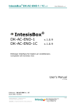
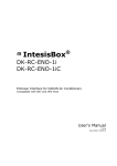
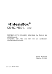
1
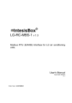
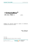
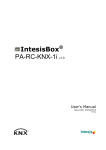
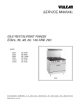
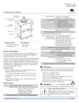
IntesisBox ® USB-ENO-ASCII USB-ENO-ASCII-C v.1.0.6 v.1.0.6 USB EnOcean gateway for IntesisBox® AC Interfaces User's Manual r4 eng Issue Date: 07/2011 IntesisBox® USB-ENO-ASCII / C © Intesis Software S.L. User’s Manual r4 eng All Rights Reserved. Information in this document is subject to change without notice. The software described in this document is furnished under a license agreement or nondisclosure agreement. The software may be used only in accordance with the terms of those agreements. No part of this publication may be reproduced, stored in a retrieval system or transmitted in any form or any means electronic or mechanical, including photocopying and recording for any purpose other than the purchaser’s personal use without the written permission of Intesis Software S.L. Intesis Software S.L. Milà I Fontanals, 1 bis, 1º 08700 Igualada Spain TRADEMARKS All trademarks and tradenames used in this document are acknowledged to be the copyright of their respective holders © Intesis Software S.L. - All rights reserved This information is subject to change without notice IntesisBox® is a registered trademark of Intesis Software SL URL Email tel http://www.intesis.com [email protected] +34 938047134 2 / 41 IntesisBox® USB-ENO-ASCII / C User’s Manual r4 eng Gateway for integration of IntesisBox® Enocean Gateways for Air Conditioners and one reference temperature sensor into USB enabled controllers or PC software using simple text messages. 2 models are available for this gateway, with the following Order Codes: USB-ENO-ASCII EnOcean communication frequency: 868 MHz USB-ENO-ASCII-C EnOcean communication frequency: 315 MHz © Intesis Software S.L. - All rights reserved This information is subject to change without notice IntesisBox® is a registered trademark of Intesis Software SL URL Email tel http://www.intesis.com [email protected] +34 938047134 3 / 41 IntesisBox® USB-ENO-ASCII / C User’s Manual r4 eng INDEX TRADEMARKS ............................................................................................................... 2 1. Presentation.................................................................................................... 5 1.1 Main Features: .............................................................................................. 5 1.2 Typical application ......................................................................................... 6 2. Connection and placement ................................................................................ 7 2.1 Connection ................................................................................................... 7 2.2 Placement .................................................................................................... 7 3. Configuration ................................................................................................. 10 3.1 Manual commissioning procedure .................................................................. 11 3.2 Remote commissioning procedure ................................................................. 12 4. Commands .................................................................................................... 13 4.1 Commands quick reference .......................................................................... 13 4.2 Error (ER) values ........................................................................................ 14 4.3 OK values................................................................................................... 14 4.4 Read .......................................................................................................... 15 4.5 Spontaneous message ................................................................................. 17 4.6 Write ......................................................................................................... 18 4.7 List linked Devices ....................................................................................... 20 4.8 Delete linked devices ................................................................................... 22 4.9 Remote commissioning ................................................................................ 23 4.10 Virtual Temperature .................................................................................... 25 4.11 Device Password ......................................................................................... 27 4.12 Get last RSSI from Device ............................................................................ 29 4.13 Configuration .............................................................................................. 30 4.14 Identification .............................................................................................. 32 4.15 Read temperature sensor ............................................................................. 33 4.16 Spontaneous temperature message ............................................................... 34 4.17 List linked temperature Devices .................................................................... 35 4.18 Delete linked temperature devices ................................................................. 36 4.19 Remote commissioning temperature sensor .................................................... 37 4.20 Get last RSSI from Temperature sensor ......................................................... 38 5. Technical data and dimensions ......................................................................... 39 6. EnOcean Interoperability Table ......................................................................... 40 6.1 Compatible IntesisBox® Air conditioner gateways ............................................ 40 6.2 Compatible temperature sensors ................................................................... 40 7. Regulations and standards ............................................................................... 41 © Intesis Software S.L. - All rights reserved This information is subject to change without notice IntesisBox® is a registered trademark of Intesis Software SL URL Email tel http://www.intesis.com [email protected] +34 938047134 4 / 41 IntesisBox® USB-ENO-ASCII / C User’s Manual r4 eng 1. Presentation Supervision and control of any IntesisBox® Enocean Gateways for Air Conditioners from USB enabled controllers or PC software using simple text messages. IntesisBox® USB-ENO-ASCII / C gateways allow supervision and bidirectional control of any IntesisBox® Enocean AC gateway and a temperature sensor from PC systems such as SCADA’s or others using simple text messages. 1.1 Main Features: Bidirectional: Supervision and Control. Up to 10 AC IntesisBox® gateways. 1 external temperature sensor as a temperature reference Control of the AC indoor units using simple text messages. Spontaneous messages avoid continuous polling Fast and easy commissioning. USB Powered. No external power supply needed. Plug and Play (virtual COM port). Suitable look for home applications. Small dimensions. © Intesis Software S.L. - All rights reserved This information is subject to change without notice IntesisBox® is a registered trademark of Intesis Software SL URL Email tel http://www.intesis.com [email protected] +34 938047134 5 / 41 IntesisBox® USB-ENO-ASCII / C 1.2 User’s Manual r4 eng Typical application In Figure 1.1 it is shown a typical integration example using the USB-ENO-ASCII / C to control and/or supervise up to 10 IntesisBox® EnOcean AC Interfaces. Figure 1.1 Integration example © Intesis Software S.L. - All rights reserved This information is subject to change without notice IntesisBox® is a registered trademark of Intesis Software SL URL Email tel http://www.intesis.com [email protected] +34 938047134 6 / 41 IntesisBox® USB-ENO-ASCII / C User’s Manual r4 eng 2. Connection and placement 2.1 Connection 1. Plug the gateway to the USB port of the computer or control system. 2. The red USB LED (Figure 3.1) will turn on. 3. Once the device has been recognized a virtual COM port is going to be generated and the LED will turn off. If that doesn’t happen the FTDI driver needs to be installed. They can be downloaded from http://www.ftdichip.com/FTDrivers.htm 4. To communicate with the gateway use the generated port. 2.1.1 Serial Port communication settings: Baud rate Stop bit Data bits Flow control Parity 9600 bps 1 8 None No Parity Table 2.1 Serial port communication settings 2.2 Placement The coverage distance (see Table 2.2) of the signal emitted by the USB-ENO-ASCII / C, or by any other EnOcean device, is determined by the room geometry and where they are placed. As an example, long narrow corridors with wide walls are an adverse situation. People or other obstacles can reduce the coverage distance too. Is therefore advice to always think in the worst possible scenario to decide the placement of the device to ensure a good stability in the radio system. Conditions Line-of-sight connections Plasterboard walls / dry wood Brick walls / aerated concrete Ferroconcrete walls / ceilings Coverage distance typically 30 m range in corridors up to 100 m in halls typically 30 m range, through 5 walls typically 20 m range, through 3 walls typically 10 m range, through 1 ceiling Table 2.2 Device coverage distance 2.2.1 Screening zones It is important not to place the device in a place where the airwaves must go through a metallic object as they create a screening zone where the receivers are not going to be able to receive the EnOcean telegrams. This situation is shown in Figure 2.1a. © Intesis Software S.L. - All rights reserved This information is subject to change without notice IntesisBox® is a registered trademark of Intesis Software SL URL Email tel http://www.intesis.com [email protected] +34 938047134 7 / 41 IntesisBox® USB-ENO-ASCII / C User’s Manual r4 eng Figure 2.1 a) Screening zone b) solution with a repeater The situation of one of the receivers doesn’t allow it to receive the transceiver telegrams. To solve this situation the use or a repeater outside the screening zone (Figure 2.1b) is recommended. The telegrams will be retransmitted from there to the receiver 2.2.2 Penetration Angle This is the angle in which the airwaves reach a certain object they need to go through. The transmission to the other side of the object would be better as this angle gets closer to 90 º, being this the best transmission situation In Figure 2.2a it is shown a receiver in a situation where the penetration angle is too close to 0º. The solution to that problem can be seen in Figure 2.2b using a repeater in a different position Figure 2.2 Penetration angle © Intesis Software S.L. - All rights reserved This information is subject to change without notice IntesisBox® is a registered trademark of Intesis Software SL URL Email tel http://www.intesis.com [email protected] +34 938047134 8 / 41 IntesisBox® USB-ENO-ASCII / C User’s Manual r4 eng 2.2.3 Use of repeaters In case of a poor radio reception, it may be helpful to use a repeater. EnOcean repeaters do not require any configuration, only a line-power supply is needed. A poor radio signal is received, refreshed and transmitted again, so nearly a double radio range can be achieved. Special EnOcean repeaters which can be switched to 2-level function allow two repeaters to be cascaded. © Intesis Software S.L. - All rights reserved This information is subject to change without notice IntesisBox® is a registered trademark of Intesis Software SL URL Email tel http://www.intesis.com [email protected] +34 938047134 9 / 41 IntesisBox® USB-ENO-ASCII / C User’s Manual r4 eng 3. Configuration In Figure 3.1 an schematic of the device can be seen. This is useful to follow the instruction in section 3.1 USB-ENO-v10-REV0 Intesis software Antenna PB1 MOD1 PB1: Button ROT1: Configuration selector ROT1 enocean ® 0 1 EF 2 D 3 C 4 B 5 A 6 9 8 7 MOD1: Enocean module CON1: USB connector USB LED: USB LED (red) COMM LED NOT LED USB LED CON1 CONF LED: Configuration LED (red) COMM LED: communication LED (green) Figure 3.1 Device diagram © Intesis Software S.L. - All rights reserved This information is subject to change without notice IntesisBox® is a registered trademark of Intesis Software SL URL Email tel http://www.intesis.com [email protected] +34 938047134 10 / 41 IntesisBox® USB-ENO-ASCII / C 3.1 User’s Manual r4 eng Manual commissioning procedure 1. Set the channel of the USB-ENO-ASCII (ROT1 in Figure 3.1) in which the IntesisBox® AC interface wants to be linked 2. Press PB1 (Figure 3.1) for 5 seconds to set the USB-ENO-ASCII to commissioning mode. The COMM LED will turn on. 3. Set profile F in the IntesisBox® AC interface (ROT1) 4. In the IntesisBox® AC interface press the teach-in button (PB1). The USB-ENO-ASCII receives the signal, stores the device in the selected channel and replies to the IntesisBox® AC interface that stores its ID 5. After blinking of the COMM LED the commissioning has finished 6. The IntesisBox® AC interface and the USBENO-ASCII are linked and ready to be used. 7. To link a temp. sensor follow the same steps using profile F 8. Once finished press PB1 to exit the commissioning mode OR © Intesis Software S.L. - All rights reserved This information is subject to change without notice IntesisBox® is a registered trademark of Intesis Software SL URL Email tel http://www.intesis.com [email protected] +34 938047134 11 / 41 IntesisBox® USB-ENO-ASCII / C 3.2 User’s Manual r4 eng Remote commissioning procedure IntesisBox® AC interfaces can be commissioned without need of using the rotary switch (ROT1 in Figure 3.1) and push button of the USB-ENO-ASCII. To do so, follow the instructions below: 1. Use the remote commissioning command (explained in section 4.9) to set the desired channel of the USB-ENO-ASCII. 2. Follow manual commissioning instructions from point 3 to 8 3. Exit the remote commissioning mode with the appropriate command (section 4.9). © Intesis Software S.L. - All rights reserved This information is subject to change without notice IntesisBox® is a registered trademark of Intesis Software SL URL Email tel http://www.intesis.com [email protected] +34 938047134 12 / 41 IntesisBox® USB-ENO-ASCII / C User’s Manual r4 eng 4. Commands All queries and responses have the same structure, which consists of one keyword followed by a comma and a list of parameters separated by commas. The following generic representation may help to understand this structure: <keyword>,<parameter_1>,…,<parameter_n> When a command is sent to USB-ENO-ASCII, it is executed by sending a carriage return (\r). Combinations with line feed are accepted, such as \r\n and \n\r. If user is typing commands manually, or a buffer flush is needed by some reason, sending the character with ASCII value 26 (CTRL+Z) will produce a flush into the command reception buffer of USB-ENO-ASCII, and the device will answer with a carriage return (\r) The sections 4.4 to 4.14 follow the same structure: A request and a response section (and their subsections if apply). In them the commands specific implementation of the abovementioned structure is explained. A subset of replies has been defined: 4.1 Command confirmation: It only specifies if the command has been accepted and transmitted, or not Procedure confirmation: It specifies if the procedure has been executed successfully or not Answer for an specific channel: Value/s of the command in the enquired channel Answer for all channels: Value of the command for all channels Commands quick reference Command RD DA SP WR LD DE CM VT PW XD CF ID RT ST LT DT CT XT ER OK Meaning Device where command applies Read Read response Spontaneous Write List devices Delete devices Remote commissioning Virtual temperature Password Get last RSSI Configuration Identification Read temperature sensor Spontaneous temperature List temperature device Delete temperature device Commissioning temperature device Get last RSSI temperature Error OK Section Section Section Section Section AC interface Section Section Section Section Section Section USB-ENO-ASCII Section Section Section Section Temperature sensor Section Section Section Section All devices Section © Intesis Software S.L. - All rights reserved This information is subject to change without notice IntesisBox® is a registered trademark of Intesis Software SL URL Email tel Section http://www.intesis.com [email protected] +34 938047134 4.4.1 4.4.2 4.5 4.6.1 4.7.1 4.8.1 4.9.1 4.10.1 4.11.1 4.12.1 4.13.1 4.14.1 4.15.1 4.16 4.17.1 4.18.1 4.19.1 4.20.1 4.2 4.3 13 / 41 IntesisBox® USB-ENO-ASCII / C 4.2 Error (ER) values Error Code 1 2 3 4 5 6 7 8 9 10 11 12 13 4.3 User’s Manual r4 eng Enumeration Name Description ERR_WRITE_NOT_LINKED ERR_WRITE_NOT_RESPONSIVE ERR_SYNTAX ERR_INCORRECT_CHANNEL ERR_INCORRECT_VALUE ERR_INCORRECT_PARAM_INDEX ERR_VT_NOT_COMPLETED ERR_CM_NOT_COMPLETED ERR_PW_NOT_COMPLETED ERR_TOO_LONG_COMMAND ERR_WRITE_ONGOING ERR_NO_ACK_RECEIVED ERR_NOT_LINKED_PROPERLY Not linked channel Non-responsive channel Syntax error Incorrect channel (channel out of range) Incorrect value (value out of range) Incorrect parameter index (index out of range) Virtual Temperature setting not applied Commissioning procedure not completed Password setting procedure not completed Entered string is too long (> 63 characters) Previous Write haven’t finished processing No ACK received when ACK is activated Data received in the ACK from an IntesisBox AC interface from an incorrect channel. If received commissioning needs to be repeated. It only works when ACK is activated OK values OK Code 0 1 2 3 4 Enumeration Name Description OK_COMMAND OK_VT_COMPLETED OK_CM_COMPLETED OK_PW_COMPLETED OK_ACK_RECEIVED Command received and parsed OK Virtual Temperature setting applied successfully Commissioning procedure completed successfully Password setting procedure completed successfully ACK received when ACK is activated © Intesis Software S.L. - All rights reserved This information is subject to change without notice IntesisBox® is a registered trademark of Intesis Software SL URL Email tel http://www.intesis.com [email protected] +34 938047134 14 / 41 IntesisBox® USB-ENO-ASCII / C 4.4 User’s Manual r4 eng Read 4.4.1 Read request Description Read status of an AC unit Keyword RD Parameters Index Size Description 1 2 AC Channel Example Description RD,03\r Read status of channel 03 Allowed Values 01 to 10 4.4.2 Read response Description The actual status of an AC unit, as a response of Read Request Keyword1 DA Parameters Index Size Description Allowed Values 1 2 AC Channel 01 to 10 2 1 AC Interface status 0 - OK 1 - No communication 2 - Not linked 3 1 On/Off status 0 - Off 1 – On 4 1 Mode status 0 – Cool 1 – Heat 2 – Fan 3 – Dry 4 – Auto 5 – Auto Heat 6 – Auto Cool 5 2 Set point temperature AC unit related 1 6 2 Ambient temperature AC unit related 1 7 1 Fan Speed 0 to 6 8 2 Vane position 00 to 14. AC unit related 9 1 IR Disablement status 0 – IR Enabled 1 – IR Disabled 10 1 Alarm status 0 – No alarm 1 – Alarm 11 4 Error code ( HEX ) AC unit related 1 1 1 Check IntesisBox® AC User Manual for details © Intesis Software S.L. - All rights reserved This information is subject to change without notice IntesisBox® is a registered trademark of Intesis Software SL URL Email tel http://www.intesis.com [email protected] +34 938047134 15 / 41 IntesisBox® USB-ENO-ASCII / C User’s Manual r4 eng Important If a parameter is unknown a literal * will be filled in its position. It happens when the USBENO-ASCII has just been turned on or when a parameter is not supplied by the AC interface Examples Description DA,03,0,0,4,25,20,1,01,1,0,0000\r Status of channel 03 with all its values Status of channel 03: No communication with the AC DA,03,1,*,*,**,**,*,**,*,*,****\r interface and no values available Keyword2 ER Parameters Index Size Description Allowed Values 1 1 Error index ERR_INCORRECT_CHANNEL Examples Description ER,4\r Incorrect channel (the channel written is out of the valid range) © Intesis Software S.L. - All rights reserved This information is subject to change without notice IntesisBox® is a registered trademark of Intesis Software SL URL Email tel http://www.intesis.com [email protected] +34 938047134 16 / 41 IntesisBox® USB-ENO-ASCII / C 4.5 User’s Manual r4 eng Spontaneous message Description Spontaneous sending on status change on AC unit. Keyword SP Parameters Index Size Description 1 2 AC Channel 2 1 AC Interface status 3 1 On/Off status 4 1 Mode status 5 6 7 8 9 2 2 1 2 1 Set point temperature Ambient temperature Fan Speed Vane position IR Disablement status 10 1 Alarm status Allowed Values 01 to 10 0 - OK 1 - No communication 2 - Not linked 0 - Off 1 – On 0 – Cool 1 – Heat 2 – Fan 3 – Dry 4 – Auto 5 – Auto Heat 6 – Auto Cool AC unit related 2 AC unit related 2 0 to 6 00 to 14. AC unit related 0 – IR Enabled 1 – IR Disabled 0 – No alarm 1 – Alarm AC unit related 2 2 11 4 Error code ( HEX ) Important If a parameter is unknown a literal * will be filled in its position. That can happen when the USB-ENO-ASCII has just been turned on or when a parameter is not supplied by the IntesisBox® AC interface Check configuration command (section 4.13) for more information about spontaneous messages configuration Examples Description (more info in section 4.13) SP,03,0,0,4,26,20,2,01,1,0,0000\r Any of the values in channel 03 has changed Only the Setpoint temperature and Fan speed in Channel SP,03,-,-,-,26,--,2,--,-,-,----\r 03 have changed SP,03,1,*,*,**,**,*,**,*,*,****\r Communication lost in Channel 03. Last data is lost SP,03,1,0,4,26,20,2,01,1,0,0000\r Communication lost in Channel 03. Last data is kept 2 Check IntesisBox® AC User Manual for details © Intesis Software S.L. - All rights reserved This information is subject to change without notice IntesisBox® is a registered trademark of Intesis Software SL URL Email tel http://www.intesis.com [email protected] +34 938047134 17 / 41 IntesisBox® USB-ENO-ASCII / C 4.6 User’s Manual r4 eng Write 4.6.1 Write request Description Write desired status to the AC unit Keyword WR Parameters Index Size Description 1 2 AC Channel 2 1 On/Off status 3 1 Mode status 4 5 6 7 8 2 2 1 1 1 Set point temperature in ºC Ambient temperature in ºC Fan Speed Vane position IR Disablement status Allowed Values 01 to 10 0 - Off 1 – On 0 – Cool 1 – Heat 2 – Fan 3 – Dry 4 – Auto AC unit related 3 AC unit related 3 0 to 6 00 to 14.AC unit related 0 – IR Enabled 1 – IR Disabled 3 Important All or only some of the parameters can be written. Fill with literal * the parameters you don’t want to change. The IR disablement status should not be toggled periodically Example Description WR,03,1,*,**,**,*,**,*\r Turn On the AC linked to channel 03 Turn On the AC linked to channel 03 and change all values WR,03,1,4,25,**,5,00,0\r but ambient temperature. 4.6.2 Write response Description An OK is only a command confirmation not a Procedure confirmation (introduction of section 4). A spontaneous would be received with the actual values written to the AC unit. The controlling system is the one responsible of processing this information. If the command is not valid, an error message will be sent. Keywords OK ER Parameters Index Size Description Allowed Values 1 1 Error or OK index OK_COMMAND OK_ACK_RECEIVED ERR_INCORRECT_CHANNEL 3 Check IntesisBox® AC User Manual for details © Intesis Software S.L. - All rights reserved This information is subject to change without notice IntesisBox® is a registered trademark of Intesis Software SL URL Email tel http://www.intesis.com [email protected] +34 938047134 18 / 41 IntesisBox® USB-ENO-ASCII / C User’s Manual r4 eng ERR_WRITE_NOT_LINKED ERR_WRITE_NOT_RESPONSIVE ERR_SYNTAX ERR_WRITE_ONGOING ERR_NO_ACK_RECEIVED ERR_NOT_LINKED_PROPERLY Notes OK_ACK_RECEIVED will only be received when ACK are activated (section 4.13). OK_COMMAND is included in it. That means that only one OK will be received. Examples Description OK,0\r The write command was correct OK,4\r The write command was correct and ACK was received (only if ACK activated (section 4.13). ER,3\r Syntax error in the write command © Intesis Software S.L. - All rights reserved This information is subject to change without notice IntesisBox® is a registered trademark of Intesis Software SL URL Email tel http://www.intesis.com [email protected] +34 938047134 19 / 41 IntesisBox® USB-ENO-ASCII / C 4.7 User’s Manual r4 eng List linked Devices 4.7.1 List request Description Returns if a channel has a device commissioned or not, its status and its ID Keyword LD Parameters Index Size Description Allowed Values 1 2 Channel index 01 to 10 – Channel ** - All the channels are listed Important Configuration parameters are stored in internal flash. Periodic writing must be avoided due to limited write cycles to flash memory. Examples Description LD,03\r List Channel 03 LD,**\r List all channels 4.7.2 List response 4.7.2.1 List response for an specific channel Description Status information of the requested channel Keyword1 LR Parameters Index Size Description 1 2 AC Channel 2 1 Bit that indicates if a commissioned in this Channel device 3 1 Bit that indicates if there communication with the AC interface 4 5 8 2 AC interface HEX ID (32 bit) AC interface identification is is Allowed Values 00 to 10 0 – Not commissioned 1- Commissioned 0 – Not communicating 1- Communicating Any 01 – ME-AC-ENO-1 / C 02 – DK-AC-ENO-1 / C 03 – DK-RC-ENO-1 / C Important Only the following combinations from index 2 and 3 are possible Index2 0 1 1 Index3 0 0 1 Channel not assigned Channel assigned, but device not responding Channel assigned and device responding radio. Examples LR,03,0,0,********,**\r Description In channel 03 there is no commissioned device © Intesis Software S.L. - All rights reserved This information is subject to change without notice IntesisBox® is a registered trademark of Intesis Software SL URL Email tel http://www.intesis.com [email protected] +34 938047134 20 / 41 IntesisBox® USB-ENO-ASCII / C LR,03,1,0,010046E9,01\r LR,03,1,1,010046E8,02\r Keyword2 ER Parameters Index Size 1 1 Examples ER,4\r In C) In C) User’s Manual r4 eng channel 03 there is a commissioned device (ME-AC-ENO-1 / with ID 010046E9 and there is no communication with it. channel 03 there is a commissioned device (DK-AC-ENO-1 / with ID 010046E8 and there is communication with it. Description Allowed Values Error index ERR_INCORRECT_CHANNEL Description Incorrect channel (the channel written is out of the valid range) 4.7.2.2 List response for all channels Description Information of the channels with linked AC interfaces Keyword LR Parameters Index Size Description Allowed Values 1 2 All AC Channel identifier ** 2 to 11 1 Linked status of the channels, being 0 – Not commissioned index 2 channel one and increasing 1 – Commissioned accordingly. Examples Description LR,**,1,0,0,0,0,0,0,0,0,0\r There is only a device commissioned in channel 01 LR,**,1,0,0,0,1,0,0,0,0,1\r There are commissioned devices in channels 01, 05 and 10 © Intesis Software S.L. - All rights reserved This information is subject to change without notice IntesisBox® is a registered trademark of Intesis Software SL URL Email tel http://www.intesis.com [email protected] +34 938047134 21 / 41 IntesisBox® USB-ENO-ASCII / C 4.8 User’s Manual r4 eng Delete linked devices 4.8.1 Delete request Description Erase a commissioned channel Keyword DE Parameters Index Size Description 1 2 Channel index Allowed Values 01 to 10 – Channel ** - All the channels are deleted Important It is extremely important that remote password is set to NOT_ASSIGNED when deleting a device. See Password command (section 4.11) Remote devices information is stored in internal flash. Periodic writing must be avoided due to limited write cycles to flash memory. Examples Description DE,03\r Delete linked device in channel 03 DE,**\r Delete linked device in all channels 4.8.2 Delete response Description Delete command confirmation Keywords OK ER Parameters Index Size Description 1 2 Error or OK index Examples OK,0\r ER,3\r Allowed Values OK_COMMAND ERR_INCORRECT_CHANNEL ERR_SYNTAX Description The Delete command was executed successfully Syntax error in the delete command © Intesis Software S.L. - All rights reserved This information is subject to change without notice IntesisBox® is a registered trademark of Intesis Software SL URL Email tel http://www.intesis.com [email protected] +34 938047134 22 / 41 IntesisBox® USB-ENO-ASCII / C 4.9 User’s Manual r4 eng Remote commissioning 4.9.1 Remote commissioning request Description Set a channel to commissioning mode Keyword CM Parameters Index Size Description 1 2 Channel index Allowed Values 00 – Exits commissioning mode 01 to 10 – Channel Important Remote devices information is stored in internal flash. Periodic writing must be avoided due to limited write cycles to flash memory. Examples Description CM,00\r Exits commissioning mode CM,03\r Sets channel 03 to commissioning mode. If a teach-in telegram from an IntesisBox® AC interface is received this device is going to be linked to channel 03 4.9.2 Remote commissioning command replies 4.9.2.1 Remote commissioning command confirmation Description Remote commissioning command confirmation Keywords OK , ER Parameters Index Size Description 1 2 Error or OK index Examples OK,0\r ER,4\r Allowed Values OK_COMMAND ERR_INCORRECT_CHANNEL Description The Remote commissioning command was executed successfully Incorrect channel (the channel written is out of the valid range) 4.9.2.2 Remote commissioning procedure confirmation Description Remote commissioning procedure confirmation. It only applies when the commissioning procedure is executed from the IntesisBox® AC interface (section 3.2) while the commissioning mode is activated Keywords OK , ER Parameters Index Size Description Allowed Values 1 2 Error or OK index OK_CM_COMPLETED ERR_CM_NOT_COMPLETED © Intesis Software S.L. - All rights reserved This information is subject to change without notice IntesisBox® is a registered trademark of Intesis Software SL URL Email tel http://www.intesis.com [email protected] +34 938047134 23 / 41 IntesisBox® USB-ENO-ASCII / C Examples OK,2\r ER,8\r User’s Manual r4 eng Description A device has been linked to the channel in commissioning mode A device has NOT been linked to the channel in commissioning mode. The procedure should be repeated © Intesis Software S.L. - All rights reserved This information is subject to change without notice IntesisBox® is a registered trademark of Intesis Software SL URL Email tel http://www.intesis.com [email protected] +34 938047134 24 / 41 IntesisBox® USB-ENO-ASCII / C User’s Manual r4 eng 4.10 Virtual Temperature The use of Virtual temperature implies that the AC unit uses an external temperature as a reference (it is supplied to the AC unit with the write command. Section 4.6) 4.10.1 Virtual temperature request Description Set a virtual temperature enablement of a given channel and updates this setting in the commissioned remote device, if it exists. Keyword VT Parameters Index Size Description Allowed Values 1 2 Channel index ** - All channels 01 to 10 – Channel 2 1 Enabling or disabling of virtual 0 – Disable Virtual temperature temperature (not needed when 1 – Enable Virtual temperature index1 value is **) ? – Enquires the channel status Important When activated the ambient temperature used by the AC unit is the one supplied using the write command. This behavior should not be activated unless a real ambient temperature is supplied When a device is commissioned with the given channel, it is configured according to the new settings. Examples VT,**\r Enquires the virtual temperature status for all channels VT,03,1\r Enables the virtual temperature in channel 03 VT,03,?\r Enquires the virtual temperature status for channel 03 4.10.2 Virtual temperature replies 4.10.2.1 Virtual temperature command confirmation Description Virtual temperature command confirmation. It only specifies if the command has been accepted and transmitted or not Keywords OK ER Parameters Index Size Description Allowed Values 1 2 Error or OK index OK_COMMAND ERR_INCORRECT_CHANNEL Examples Description OK,0\r The virtual temperature command was executed successfully ER,4\r Incorrect channel (the channel written is out of the valid range) © Intesis Software S.L. - All rights reserved This information is subject to change without notice IntesisBox® is a registered trademark of Intesis Software SL URL Email tel http://www.intesis.com [email protected] +34 938047134 25 / 41 IntesisBox® USB-ENO-ASCII / C 4.10.2.2 User’s Manual r4 eng Virtual temperature procedure confirmation Description It only applies when the virtual temperature command confirmation it’s been OK_COMMAND and there is a linked device in the channel. It specifies if the procedure has been executed successfully or not Keywords OK ER Parameters Index Size Description Allowed Values 1 2 Error or OK index OK_VT_COMPLETED ERR_VT_NOT_COMPLETED Examples Description OK,1\r The linked device in Channel 03 has been configured to work with virtual temperature (external temperature reference) ER,7\r Error while trying to set the linked device to work with virtual temperature 4.10.2.3 Virtual temperature answer for an specific channel Description It only applies when there is an enquire in the channel status Keywords VT Parameters Index Size Description Allowed Values 1 2 Channel index 01 to 10 – Channel 2 1 Virtual temperature status 0 – Virtual temperature disabled 1 – Virtual temperature enabled Examples Description VT,03,1\r Channel 03 is working with virtual temperature 4.10.2.4 Virtual temperature answer for an all channels Description It only applies when there is an enquire in the channel status Keywords VT Parameters Index Size Description Allowed Values 1 2 Channel index ** - All channels 2 to 11 1 Virtual temperature status of the 0 – Virtual temperature disabled channels, being index2 channel one 1 – Virtual temperature enabled and increasing accordingly. Examples Description VT,**,1,0,0,0,0,0,0,0,0,0\r Only channel 01 is working with virtual temperature © Intesis Software S.L. - All rights reserved This information is subject to change without notice IntesisBox® is a registered trademark of Intesis Software SL URL Email tel http://www.intesis.com [email protected] +34 938047134 26 / 41 IntesisBox® USB-ENO-ASCII / C User’s Manual r4 eng 4.11 Device Password 4.11.1 Password request Description Sets or gets the Keyword PW Parameters Index Size 1 2 2 8 password in the remote device of the given channel. Description Allowed Values Channel index 01 to 10 – Channel 32-bit value expressed in hex that sets ???????? – Enquires the password the password Any HEX value: sets that value Important It is extremely important that remote password is set to NOT_ASSIGNED when deleting a device (section 4.8). A password is considered NOT_ASSIGNED when is filled with zeros (i.e.: 0x00000000) During the password setting procedure, some spontaneous can be sent by USB-ENO-ASCII to USB UART due to remote device rebooting. Password setting is stored in internal flash. Periodic writing must be avoided due to limited write cycles to flash memory. Examples Description PW,03,?\r Enquires the password in channel 03 PW,03,ABCD1234\r Sets the password in channel 03 to 0xABCD1234 PW,03,00000000\r Sets the password in channel 03 to NOT_ASSIGNED (it is deleted) 4.11.2 Password response 4.11.2.1 Password command confirmation Description Password command confirmation. It only specifies if the command has been accepted and transmitted or not Keywords OK ER Parameters Index Size Description Allowed Values 1 2 Error or OK index OK_COMMAND ERR_INCORRECT_VALUE ERR_INCORRECT_CHANNEL ERR_SYNTAX Examples Description OK,0\r The password command was executed successfully ER,4\r Incorrect channel (the channel written is out of the valid range) © Intesis Software S.L. - All rights reserved This information is subject to change without notice IntesisBox® is a registered trademark of Intesis Software SL URL Email tel http://www.intesis.com [email protected] +34 938047134 27 / 41 IntesisBox® USB-ENO-ASCII / C 4.11.2.2 User’s Manual r4 eng Password procedure confirmation Description It only applies when the password command confirmation it’s been OK_COMMAND. It specifies if the procedure has been executed successfully or not Keywords OK ER Parameters Index Size Description Allowed Values 1 2 Error or OK index OK_PW_COMPLETED ERR_PW_NOT_COMPLETED Examples Description OK,3\r The password has been applied to the IntesisBox® AC interface ER,9\r The password has NOT been applied to the IntesisBox® AC interface. There might be no communication or no linked device in the Channel 4.11.2.3 Password answer Description It only applies when there is an enquire in the channel password Keywords PW Parameters Index Size Description Allowed Values 1 2 Channel index 01 to 10 – Channel 2 8 32-bit value expressed in hex that sets Any HEX value: sets that value the password Examples Description PW,03,ABCD1234\r The password in channel 03 is 0xABCD1234 PW,03,00000000\r The password in channel 03 is NOT_ASSIGNED (it has no password) © Intesis Software S.L. - All rights reserved This information is subject to change without notice IntesisBox® is a registered trademark of Intesis Software SL URL Email tel http://www.intesis.com [email protected] +34 938047134 28 / 41 IntesisBox® USB-ENO-ASCII / C User’s Manual r4 eng 4.12 Get last RSSI from Device 4.12.1 Get RSSI request Description Returns the last Keyword XD Parameters Index Size 1 2 Examples XD,01\r Received Signal Strength Indication from the given channel Description Channel index Description Get RSSI from Channel 01 Allowed Values 01 to 10 – Channel 4.12.2 Get RSSI response Description RSSI value from Keyword1 XD Parameters Index Size 1 2 2 1 the requested channel XD,01,45\r Description Allowed Values Channel 01 to 10 RSSI value in dBm. Note that the value should be 45 to 99 negative, but is represented without sign. Excellent communication: -45dBm Normal communication: -45dBm to -75dBm Poor communication: -75 dBm to -90 dBm No communication, or very unstable: Below -90 dBm Description In channel 01 there is no commissioned device, or no telegram received yet. In channel 01 there is a commissioned device and the last RSSI is -45 dBm Keyword2 ER Parameters Index Size 1 1 Examples ER,4\r Description Allowed Values Error index ERR_INCORRECT_CHANNEL Description Incorrect channel (the channel written is out of the valid range) Examples XD,01,**\r © Intesis Software S.L. - All rights reserved This information is subject to change without notice IntesisBox® is a registered trademark of Intesis Software SL URL Email tel http://www.intesis.com [email protected] +34 938047134 29 / 41 IntesisBox® USB-ENO-ASCII / C User’s Manual r4 eng 4.13 Configuration 4.13.1 Configuration request Description Sets or gets a configuration parameter in the USB-ENO-ASCII Keyword CF Parameters Index Size Description Allowed Values 1 2 Configuration Parameter number 01 to 07 2 2 Value ?? – requests parameter value Other values in following table Configuration parameters allowed values Parameter Size Description Allowed Values number 00 - Disable 01 2 Spontaneous sending enabled 01 - Enable (default) 00 - Disable 02 2 Echo enabled 01 - Enable (default) 00 - Disable 03 2 Error Led enabled 01 - Enable (default) 00 - Disable Communication and commissioning Led 04 2 enabled 01 - Enable (default) Spontaneous send only changes. If enabled 00 - Disable 05 2 only the changes will be send. The other 01 - Enable (default) parameters will be set to literal “-“ 15 to 1270 06 2 to 4 Ping interval [seconds] 00 – Disable ping Keep values when communication is lost. If 00 - Disable (default) 07 2 disabled the values of the channels will be 01 - Enable set to literal * if the communication is lost. 00 - Disable (default) 08 2 Enable ACK 01 - Enable 00 - Disable Write only if change in data. When working 09 2 with ACK it is recommended to disable it 01 - Enable (default) Important Configuration parameters are stored in internal flash. Periodic writing must be avoided due to limited write cycles to flash memory. Examples Description CF,01,01\r Enables spontaneous messages CF,01,??\r Request if the spontaneous messages are enabled or not © Intesis Software S.L. - All rights reserved This information is subject to change without notice IntesisBox® is a registered trademark of Intesis Software SL URL Email tel http://www.intesis.com [email protected] +34 938047134 30 / 41 IntesisBox® USB-ENO-ASCII / C User’s Manual r4 eng 4.13.2 Configuration response 4.13.2.1 Configuration command and procedure confirmation Description It’s a configuration command confirmation Keywords OK ER Parameters Index Size Description 1 1 Error or OK index Examples OK,0\r ER,3\r 4.13.2.2 Allowed Values OK_COMMAND ERR_INCORRECT_CHANNEL ERR_WRITE_NOT_LINKED ERR_WRITE_NOT_RESPONSIVE ERR_SYNTAX Description The write command was correct Syntax error in the write command Configuration answer Description It only applies when there is an enquire in the channel Keyword CF Parameters Index Size Description 1 2 Configuration Parameter 2 2 Value of the parameter Examples Description CF,01,01\r Spontaneous messages are enabled © Intesis Software S.L. - All rights reserved This information is subject to change without notice IntesisBox® is a registered trademark of Intesis Software SL Allowed Values 01 to 07 Values from the request table URL Email tel http://www.intesis.com [email protected] +34 938047134 31 / 41 IntesisBox® USB-ENO-ASCII / C User’s Manual r4 eng 4.14 Identification 4.14.1 Identification request Description Retrieves device information Keyword ID Parameters No parameters Example Description ID\r Retrieves device information 4.14.2 Identification response Description Device information containing: Device name Firmware version Manufacturer Keyword OK. It is used to terminate the information Example USB-ENO-ASCII\r FW ver: v1.0.3\r Intesis Software, SL (C) 2011\r \r OK,0\r © Intesis Software S.L. - All rights reserved This information is subject to change without notice IntesisBox® is a registered trademark of Intesis Software SL URL Email tel http://www.intesis.com [email protected] +34 938047134 32 / 41 IntesisBox® USB-ENO-ASCII / C User’s Manual r4 eng 4.15 Read temperature sensor 4.15.1 Read temperature sensor request Description Read status of an EnOcean temperature sensor Keyword RT Parameters Index Size Description 1 2 Temperature Sensor Channel Example Description RT,01\r Read status of temperature channel 01 Allowed Values 01 to 01 4.15.2 Read temperature sensor response Description The actual status of an EnOcean temperature sensor, as a response of Read Request Keyword1 RT Parameters Index Size Description Allowed Values 1 2 Temperature Channel 01 2 1 Temperature sensor status 0 - OK 2 - Not linked 3 5 Temperature (ºC). Signed fixed point value, -99.9 to +99.9 with 1 decimal precision Important If a parameter is unknown a literal * will be filled in its position. It happens when the USBENO-ASCII has just been turned on or when a parameter is not supplied by the temperature sensor Examples Description RT,01,0,+24.6\r Temperature channel 01 has a temperature of 24.6ºC RT,01,0,*****\r Status of temperature channel 01: no value available Keyword2 ER Parameters Index Size Description Allowed Values 1 1 Error index ERR_INCORRECT_CHANNEL ERR_SYNTAX Examples Description ER,4\r Incorrect channel (the channel written is out of the valid range) © Intesis Software S.L. - All rights reserved This information is subject to change without notice IntesisBox® is a registered trademark of Intesis Software SL URL Email tel http://www.intesis.com [email protected] +34 938047134 33 / 41 IntesisBox® USB-ENO-ASCII / C User’s Manual r4 eng 4.16 Spontaneous temperature message Description Spontaneous sending on status change on temperature sensor. Keyword ST Parameters Index Size Description Allowed Values 1 2 Temperature Sensor Channel 01 to 01 2 1 Temperature sensor status 0 - OK 2 - Not linked 3 5 Temperature (ºC). Signed fixed point value, -99.9 – +99.9 with 1 decimal precision Important If a parameter is unknown a literal * will be filled in its position. It happens when the USBENO-ASCII has just been turned on or when a parameter is not supplied by the temperature sensor Check configuration command (section 4.13) for more information about spontaneous messages configuration Examples Description (more info in section 4.13) ST,01,0,24.8\r Any of the values in temperature channel 01 has changed Only the temperature in temperature channel 01 has ST,-,24.8\r changed © Intesis Software S.L. - All rights reserved This information is subject to change without notice IntesisBox® is a registered trademark of Intesis Software SL URL Email tel http://www.intesis.com [email protected] +34 938047134 34 / 41 IntesisBox® USB-ENO-ASCII / C User’s Manual r4 eng 4.17 List linked temperature Devices 4.17.1 List request Description Returns if a channel has a device commissioned or not, its status and its ID Keyword LT Parameters Index Size Description Allowed Values 1 2 Temperature Channel index 01 to 01 – Channel Examples Description LT,01\r List Temperature Channel 01 4.17.2 List response Description Status information of the requested temperature channel Keyword1 LT Parameters Index Size Description 1 2 Temperature Channel 2 1 Bit that indicates if a device is commissioned in this Channel 3 1 Bit that indicates if there is communication with the temperature sensor (always 1) 4 5 8 2 Temperature sensor HEX ID (32 bit) Temperature sensor HEX ORG 6 2 Temperature sensor HEX Function 7 2 Temperature sensor HEX Type Examples LT,01,0,0,********,**,**,**\r LT,01,1,1,00038263,07,10,02\r Keyword2 ER Parameters Index Size 1 1 Examples ER,4\r Allowed Values 01 to 01 0 – Not commissioned 1- Commissioned 0 – Not communicating 1- Communicating Any Any (see interoperability table) Any (see interoperability table) Any (see interoperability table) Description In channel 01 there is no commissioned temperature sensor In channel 01 there is a commissioned temperature sensor with ID 00038263 and EEP [07-10-02] Description Allowed Values Error index ERR_INCORRECT_CHANNEL Description Incorrect channel (the channel written is out of the valid range) © Intesis Software S.L. - All rights reserved This information is subject to change without notice IntesisBox® is a registered trademark of Intesis Software SL URL Email tel http://www.intesis.com [email protected] +34 938047134 35 / 41 IntesisBox® USB-ENO-ASCII / C User’s Manual r4 eng 4.18 Delete linked temperature devices 4.18.1 Delete temperature device request Description Erase a commissioned temperature channel Keyword DT Parameters Index Size Description Allowed Values 1 2 Channel index 01 to 01 – Channel Important Remote devices information is stored in internal flash. Periodic writing must be avoided due to limited write cycles to flash memory. Examples Description DT,01\r Delete linked temperature device in channel 01 4.18.2 Delete temperature device response Description Delete command confirmation Keywords OK ER Parameters Index Size Description 1 2 Error or OK index Examples OK,0\r ER,3\r Allowed Values OK_COMMAND ERR_INCORRECT_CHANNEL ERR_SYNTAX Description The Delete command was executed successfully Syntax error in the delete command © Intesis Software S.L. - All rights reserved This information is subject to change without notice IntesisBox® is a registered trademark of Intesis Software SL URL Email tel http://www.intesis.com [email protected] +34 938047134 36 / 41 IntesisBox® USB-ENO-ASCII / C User’s Manual r4 eng 4.19 Remote commissioning temperature sensor 4.19.1 Remote commissioning temperature sensor request Description Set a temperature sensor channel to commissioning mode Keyword CT Parameters Index Size Description Allowed Values 1 2 Channel index 00 – Exits commissioning mode 01 – Channel 01 Important Remote devices information is stored in internal flash. Periodic writing must be avoided due to limited write cycles to flash memory. Examples Description CT,00\r Exits commissioning mode CT,01\r Sets channel 01 to commissioning mode. If a teach-in telegram from an EnOcean temperature sensor is received this device is going to be linked to channel 01 4.19.2 Remote commissioning temperature sensor command replies 4.19.2.1 Remote commissioning temperature sensor command confirmation Description Remote commissioning temperature sensor command confirmation Keywords OK ER Parameters Index Size Description Allowed Values 1 2 Error or OK index OK_COMMAND ERR_INCORRECT_CHANNEL Examples Description OK,0\r The Remote commissioning command was executed successfully ER,4\r Incorrect channel (the channel written is out of the valid range) © Intesis Software S.L. - All rights reserved This information is subject to change without notice IntesisBox® is a registered trademark of Intesis Software SL URL Email tel http://www.intesis.com [email protected] +34 938047134 37 / 41 IntesisBox® USB-ENO-ASCII / C User’s Manual r4 eng 4.20 Get last RSSI from Temperature sensor 4.20.1 Get RSSI temperature sensor request Description Returns the last Received Signal Strength Indication from the given temperature channel Keyword XT Parameters Index Size Description Allowed Values 1 2 Temperature Channel index 01 to 01 – Channel Important Examples XT,01\r Description Get RSSI from Temperature Channel 01 4.20.2 Get RSSI temperature sensor response Description RSSI value from the requested temperature channel Keyword1 XT Parameters Index Size Description Allowed Values 1 2 Channel 01 to 10 2 1 RSSI value in dBm. Note that the value should be 45 to 99 negative, but is represented without sign. Excellent communication: -45dBm Normal communication: -45dBm to -80dBm Poor communication: -80 dBm to -90 dBm No communication, or very unstable: Below -90 dBm Examples Description In channel 01 there is no commissioned device, or no telegram received XT,01,**\r yet. XT,01,65\r In channel 01 there is a commissioned device and the last RSSI is -65 dBm Keyword2 ER Parameters Index Size Description Allowed Values 1 1 Error index ERR_INCORRECT_CHANNEL Examples Description ER,4\r Incorrect channel (the channel written is out of the valid range) © Intesis Software S.L. - All rights reserved This information is subject to change without notice IntesisBox® is a registered trademark of Intesis Software SL URL Email tel http://www.intesis.com [email protected] +34 938047134 38 / 41 IntesisBox® USB-ENO-ASCII / C User’s Manual r4 eng 5. Technical data and dimensions The main features of the devices USB-ENO-ASCII / C are shown in Table 6.1. For further detail check the USB-ENO-ASCII / C datasheet Dimensions Weight Operating Temperature Stock Temperature Operating Humidity Stock Humidity Power requirements EnOcean Frequencies 71 x 71 x 27 mm 60 g -25 . . . 85ºC -40 . . . 85ºC <93% HR, non-condensing <93% HR, non-condensing USB powered. 50mA USB-ENO-ASCII: 868 MHz USB-ENO-ASCII-C: 315 MHz Table 5.1 Technical data © Intesis Software S.L. - All rights reserved This information is subject to change without notice IntesisBox® is a registered trademark of Intesis Software SL URL Email tel http://www.intesis.com [email protected] +34 938047134 39 / 41 IntesisBox® USB-ENO-ASCII / C User’s Manual r4 eng 6. EnOcean Interoperability Table In this section there is a list of the allowed devices 6.1 Compatible IntesisBox® Air conditioner gateways In Table 6.1 the compatible IntesisBox® AC gateways are listed. USB-ENO-ASCII ME-AC-ENO-1 DK-AC-ENO-1 DK-RC-ENO-1 USB-ENO-ASCII-C ME-AC-ENO-1-C DK-AC-ENO-1-C DK-RC-ENO-1-C Table 6.1 Device compatibility The IntesisBox® Air conditioner gateways use all the following EEP’s: EEP4 [07-10-03] [07-20-10] [07-20-11] EEP description Temperature Sensor; Set Point Control HVAC Components. Generic HVAC interface. Functions: Mode, vane position, fan speed, sensors and on/off HVAC Components. Generic HVAC interface. Functions: Error control: AC Error code, Error states and disablements Any EnOcean IntesisBox® AC gateways not specified in this list might not be compatible. To check the model compatibility, contact your USB-ENO-ASCII / C supplier for this. 6.2 Compatible temperature sensors Any temperature sensor using one of the following EEPs can be used with the USB-ENOASCII EEP Rx [07-02-04] [07-02-05] [07-02-06] [07-02-07] [07-02-11] [07-02-12] [07-02-13] [07-02-14] [07-02-15] [07-02-16] [07-02-17] [07-10-xx] 4 EEP description Temperature Sensor. Range -10°C to +30°C Temperature Sensor. Range 0°C to +40°C Temperature Sensor. Range +10°C to +50°C Temperature Sensor. Range +20°C to +60°C Temperature Sensor. Range -50°C to +30°C Temperature Sensor. Range -40°C to +40°C Temperature Sensor. Range -30°C to +50°C Temperature Sensor. Range -20°C to +60°C Temperature Sensor. Range -10°C to +70°C Temperature Sensor. Range 0°C to +80°C Temperature Sensor. Range +10°C to +90°C Room controller panel. Range 0ºC to +40ºC EnOcean Equipment Profiles (EEP) V2.1 © Intesis Software S.L. - All rights reserved This information is subject to change without notice IntesisBox® is a registered trademark of Intesis Software SL URL Email tel http://www.intesis.com [email protected] +34 938047134 40 / 41 IntesisBox® USB-ENO-ASCII / C User’s Manual r4 eng 7. Regulations and standards CE conformity: R&TTE EU-directive on Radio and Telecommunications Terminal Equipment The general registration for the radio operation is valid for all EU countries as well as for Switzerland. Standards: UNE-EN UNE-EN UNE-EN UNE-EN 50491-3:2010 60950-1:2007 61000-6-2:2006 61000-6-3:2007 FCC ID: SZV-STM300C IC: 5731A-STM300C The enclosed device complies with Part 15 of the FCC Rules. Operation is subject to the following two conditions: (i.) this device may not cause harmful interference and (ii.) this device must accept any interference received, including interference that may cause undesired operation. Warning: Changes or modifications made to this equipment not expressly approved by Intesis Software may void the FCC authorization to operate this equipment. © Intesis Software S.L. - All rights reserved This information is subject to change without notice IntesisBox® is a registered trademark of Intesis Software SL URL Email tel http://www.intesis.com [email protected] +34 938047134 41 / 41